Blue Ridge BM12MCC User manual

Ceiling Cassette
Indoor Air Handler
Installation Manual
Models:
BM12MCC
BM18MCC
IMPORTANT NOTE:
Read this manual carefully before
installing or operating your new air
conditioning unit. Make sure to save this
manual for future reference.
This manual only describes the outdoor
unit of user’s. When using the indoor unit,
refer to the user’s manual of indoor unit.


Table of Contents
1. Safety Precautions .........................................................................................................................................02
Warnings.................................................................................................................................................................. 04
Cautions ................................................................................................................................................................... 05
2. Installation Summary...................................................................................................................................06
3. Accessories .........................................................................................................................................................07
4. Indoor Unit Installation .............................................................................................................................09
5. Refrigerant Piping Installation .............................................................................................................12
6. Connecting the Drain Pipe ......................................................................................................................14
7. Electrical Wiring Work ................................................................................................................................16
8. Decorative Panel Installation ................................................................................................................17

1
WARNING
WARNING
CAUTION
Page 4 Revised 5/14/2020
Safety Precautions
Read Before Using
Incorrect usage may cause serious damage or injury.
The seriousness of potential damage or injuries is classied as either a WARNING or CAUTION.
This symbol indicates that ignoring instructions may cause death or
serious injury.
This symbol indicates that ignoring instructions may cause moderate
injury to your person, or damage to your unit or other property.
This symbol indicates that you must never perform the action indicated.
• Installation must be performed in accordance with the requirement of NEC and CEC by
authorized personnel only.
• Be sure only trained and qualied service personnel install, repair or service the equipment.
• Improper installation, repair, and maintenance may result in electric shocks, short-circuit,
leaks, personal injury, loss of life, re or other damage to the equipment.
• Install according to this installation instructions strictly. If installation is defective, it will cause
water leakage, electrical shock and re.
• When installing the unit in a small room, take measures against to keep refrigerant
concentration from exceeding allowable safety limits in the event of refrigerant leakage.
Contact the place of purchase for more information. Excessive refrigerant in a closed
ambient can lead to oxygen deciency.
• Use the attached accessories parts and specied parts for installation. Otherwise, it will cause
the unit to fall, leak water, cause electrical shock, or produce re.
• Install at a strong and rm location which is able to withstand the unit's weight. If the
strength is not enough or installation is not properly done, the set will drop causing injury.
• The appliance must be installed 8' above oor.
• The appliance shall not be installed in the laundry room.
• Before obtaining access to terminals, all supply circuits must be disconnected.
• Read this manual thoroughly before starting up the units.
• For electrical work, follow all local and national wiring codes and these installation
instructions. An independent circuit and electrical disconnect must be used. If electrical
circuit capacity is not enough or defect in electrical work, it will cause electrical shock or re.
• Use the specied cable and connect tightly and clamp the cable so that no external force will
be acted on the terminal. If connection or xing is not perfect, it can cause malfunction or re
at the connection.
WARNING
CAUTION
• Ground the air conditioner.
• Be sure to install an earth leakage breaker. Failure to install an earth leakage breaker may result
in electric shocks.
• Connect the outdoor unit wires, then connect the indoor unit wires.
DO NOT connect the ground wire to gas or water pipes, lightning rod or a telephone ground
wire. Inappropriate grounding may result in electric shocks.
DO NOT connect the air conditioner with the power supply until the wiring and piping is done.
DO NOT operate your air conditioner in a wet room such as a bathroom or laundry room.
DO NOT install the air conditioner in the following circumstance:
• There are combustible gases present.
• There is salty air surrounding (near the coast).
• There is caustic gas (the sulde, for example) existing in the air (near a hot spring).
• There is excessive vibration, as in a shop or factory.
• In small, hot industrial space such as a server room or commercial kitchen.
• In kitchen where it is full of oil gas.
• There is strong electromagnetic waves existing.
• There are inammable materials or gas.
• There is acid or alkaline liquid evaporating.
• Other special conditions.
Page 5
Revised 5/14/2020
• Wiring routing must be properly arranged so that control board cover is xed properly.
If control board cover is not xed perfectly, it can cause heat-up at connection point of
terminal, re or electrical shock.
• If the supply cord is damaged, it must be replaced by the manufacture or its service agent or
a similarly qualied person in order to avoid a hazard.
• An electrical disconnect switch having a contact separation of at least 0.12in in all poles
should be connected in xed wiring.
• When carrying out piping connection, take care to not let air substances go into refrigeration
cycle. Otherwise, it can cause lower capacity, abnormally high pressure in the refrigeration
cycle, explosion and injury.
• Do not share the single circuit with other electrical appliances. Otherwise, it can cause poor
performance, re or electrical shock.
• If the refrigerant leaks during installation, ventilate the area immediately. Toxic gas may be
produced if the refrigerant comes in contact with re.
• The temperature of refrigerant circuit will be high, please keep the interconnection cable
away from the copper tube.
• After completing the installation work, check that the refrigerant does not leak. Toxic gas may
be produced if the refrigerant leaks into the room and comes into contact with a source of
re, such as a fan heater, stove or cooker.
• After completing the installation, make sure that the unit operates properly during the start-
up operation.

2
Installation information
• To install properly, please read this "installation manual" at rst.
• The air conditioner must be installed by qualied persons.
• When installing the indoor unit or its tubing, please follow this manual as strictly as possible.
• If the air conditioner is installed on a metal part of the building, it must be electrically insulated
according to the relevant standards to electrical appliances.
• When all the installation work is nished, please turn on the power only after a thorough check.
• Regret for no further announcement if there is any change of this manual caused by product
improvement.
Installation order
1. Indoor unit installation
2. Outdoor unit installation
3. Install the refrigerant pipe
4. Connect the drain pipe
5. Electric wiring work
6. Installation of the decoration panel
7. Test operation
Installation
Summary
Page 6 Revised 5/14/2020
Installation Summary
Check o when completed
Is the indoor unit xed rmly?
The unit may drop, vibrate or make noise.
Is the gas leak test nished?
It may result in insucient cooling or heating.
Is the unit fully insulated?
Condensate water may drip.
Does drainage ow smoothly?
Condensate water may drip.
Does the power supply voltage correspond to that shown on
the name plate?
The unit may malfunction or components may burn out.
Are wiring and piping correct?
The unit may malfunction or components may burn out.
Is the unit safely grounded?
Dangerous at electric leakage.
Is the wiring size in accordance with specications?
The unit may malfunction or components may burn out.
Is anything blocking the air outlet or inlet of either the indoor
or outdoor units?
It may result in insucient cooling or heating.
Are refrigerant piping length and additional refrigerant
charge noted down?
The refrigerant charge in the system might not be clear.

Accessories
Page 7
Revised 5/14/2020
3
Accessories
The air conditioning system includes the following accessories. Use all of the installation parts and
accessories to install the air conditioner. Improper installation may result in water leakage, electrical
shock, re, or equipment failure.
Name Shape Quantity
Remote control 1
Batteries 2
Tapping screws
(M3X10mm)
(on some models)
2
Metal champ
(on some models) 1
Fixing screw for remote
control holder
ST2.9 x 10
2
Optional
Parts
Remote control holder 1
Drain hose
(on some models) 1
Expansible hooks
(on some models) 4
Installation hooks
(on some models) 4
Throttle
(on some models) 1
Anti-shock rubber
(on some models) 1
This indoor unit requires installation of an optional decoration panel.
Page 8 Revised 5/14/2020
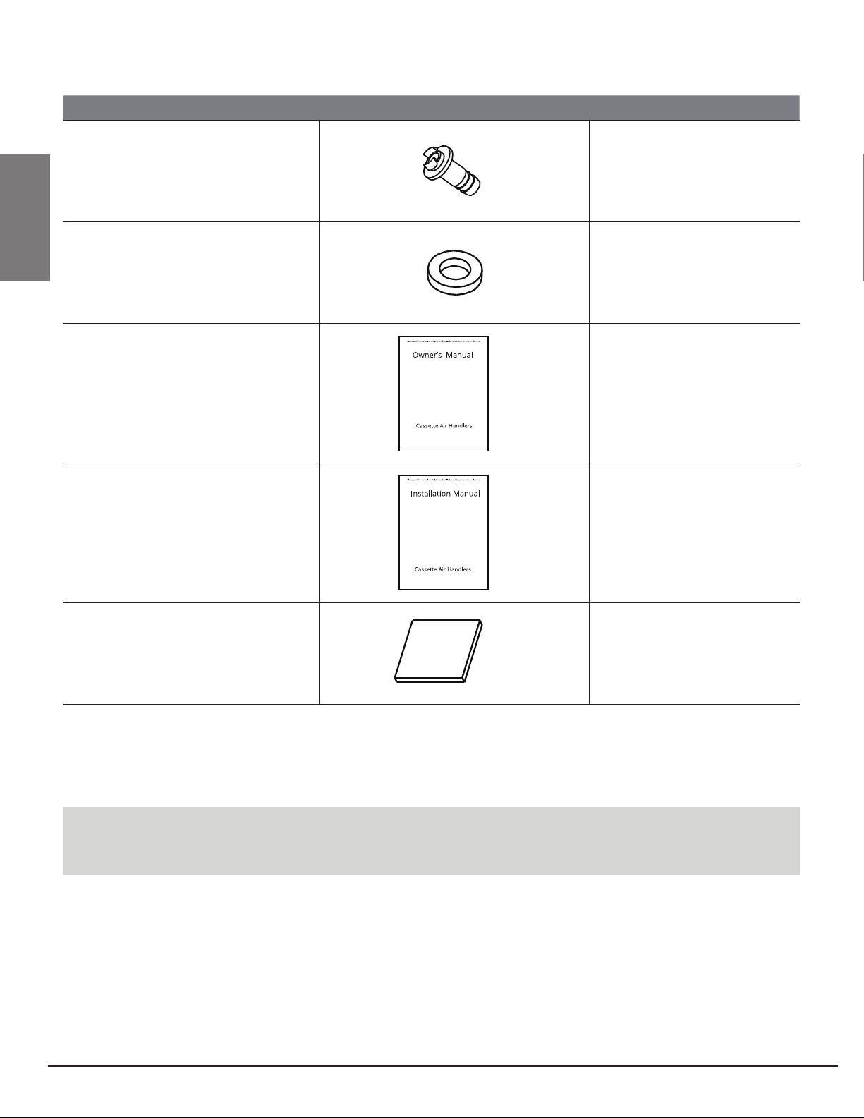
Name Shape Quantity
Drain plug
(only heat pump models)
(with the outdoor unit)
1
Seal ring
(only heat pump models)
(with the outdoor unit)
1
Owner’s Manual 1
Installation Manual 1
Paper pattern for
installation (on some
models)
1
NOTE: All the pictures in this manual are for explanation purpose only. There may be slightly
dierent from the air conditioner you purchased ( depend on model ). The actual shape may vary.
Accessories
WARNING
Do not install the unit in an area where
ammable materials are present due to risk of
explosion resulting in serious injury or death.
If the basis underneath the unit is not strong
enough to support the weight of the unit,
the unit could be fall out of place and cause
serious injury.
Fig 4.1
Page 9
Revised 5/14/2020
4
Selecting Installation Site
When the conditions in the ceiling are exceeding
86°F and a relative humidity of 80%, or when
fresh air is inducted into the ceiling, an additional
insulation is required (minimum 0.4in / thickness,
polyethylene foam).
1. Select an installation site where the following
conditions are fullled and that meets your
customer's approval.
• Where optimum air distribution can be ensured.
• Where nothing blocks air passage.
• Where condensate water can be properly
drained.
• Where the ceiling is level, not noticeably on an
incline.
• Where sucient clearance for maintenance and
service can be ensured.
• Where there is no risk of ammable gas leaking.
• The equipment is not intended for use in a
potentially explosive atmosphere.
• Where piping between indoor and outdoor units
does not exceed the allowable limit. (Refer to
the installation manual of the outdoor unit.)
• Keep indoor unit, outdoor unit, inter unit wiring
and remote control wiring at least 3 feet away
from televisions and radios. This is to prevent
image interference and noise in those electrical
appliances. (Noise may be generated depending
on the conditions under which the electric wave
is generated, even if proper distance is kept.)
• When installing the wireless remote control kit,
the distance between wireless remote control
and indoor unit might be shorter if there are
uorescent lights that are electrically started in
the room. The indoor unit must be installed as
far away as possible from uorescent lights.
2. Ceiling height
Install this unit where the height of bottom panel is
more than 8' so that the user cannot easily touch.
Indoor Unit Installation
22
1
39.4in
39.4in
39.4in
39.4in
39.4in
39.4in
98.4in
10.2in
11.4in
1
Air inlet
2 Air outlet
3. Use Threaded Rod for Installation
Use threaded rod for installation. Check whether
the ceiling is strong enough to support the weight
of the indoor unit. If there is a risk, reinforce the
ceiling before installing the unit. Space required for
installation. See Fig. 4.4 on the next page for details.
Indoor Unit
Installation

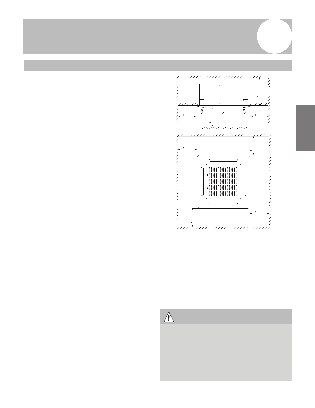
Preparations before installation
1. Relation of ceiling opening to unit and
suspension bolt position.
1. Installation hook pitch dimensions
2. Indoor unit dimensions
3. Decoration panel dimensions
4. Refrigerant piping
5. Installation hook
6. Ceiling opening dimensions
7. Hanger bracket
8. False ceiling
Adjust the position to ensure the gaps between
the indoor unit and the four sides of false ceiling
are even. The indoor unit's lower part should sink
into the false ceiling for 0.9in. See Fig. 4.3.
2. Create the ceiling opening needed for
indoor installation where applicable. (For
existing ceilings.)
• Create the ceiling opening required for
installation. From the side of the opening to
the casing outlet, implement the refrigerant
and drain piping and wiring for remote
control (unnecessary for wireless type). Refer
to each piping or wiring section.
• After making an opening in the ceiling, it may
be necessary to reinforce ceiling beams to
keep the ceiling level and to prevent it from
vibrating. Consult the builder for details.
3. Install the threaded rod. (Use either a M8 or
M10 size rod.)
• Use expansible hooks, sunken anchors or
other eld supplied parts to reinforce the
ceiling in order to bear the weight of the unit.
• Adjust clearance from the ceiling before
proceeding further. See Fig. 4.4 for
Installation example.
Fig 4.2
Fig 4.3
Fig 4.4
1
Indoor unit
2
False ceiling
1
2
0.9in
1
Ceiling slab
2
Expansible hook (optional)
3
Installation hook (optional)
4 False ceiling
1.2~1.4in
1
2
3
4
Page 10 Revised 5/14/2020
NOTE: The opening in the ceiling should not
be larger than the decorative grill, otherwise
additional ceiling patching will be required.
For other installation other than standard
installation, contact your dealer for details.
1
1
2
2
3
3
21.5in
20.6in
22.4in
22.4in
25.5in
25.5in
45
2.8in
0.6in0.6in23.6in6
7
8
0.8in0.8in
Indoor Unit
Installation
Install the indoor unit
When installing optional accessories, read
also the installation manual of the optional
accessories. Depending on the eld conditions,
it may be easier to install optional accessories
before the indoor unit is installed (except for the
decoration panel). However, for existing ceiling,
install fresh air inlet component kit and branch
duct before installing the unit.
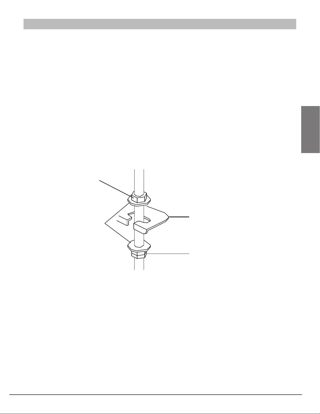
1. Install the indoor unit.
1. Attach the hanger bracket to the threaded
rod. Be sure to x it securely by using a nut
and washer from the upper and lower sides
of the hanger bracket.
2. Securing the hanger bracket see gure
below.
2. Adjust the unit to the right position for
installation.
(Refer to the chapter "Preparations before
installation").
3. Check if the unit is horizontally leveled.
• Do not install the unit tilted. The indoor unit
is equipped with a built-in drain pump and
oat switch. (If the unit is tilted against the
direction of the condensate ow (the drain
piping side is raised), the oat switch may
malfunction and cause water to drip.)
• Check to ensure the unit is level at all four
corners.
Fig 4.5
Nut (field supply)
Washer
(field supply)
Hanger
bracket
Double nuts
(field supply,
tighten)
Page 11
Revised 5/14/2020
Indoor Unit
Installation

CAUTION
• DO NOT mix anything other than the specied refrigerant, such as air, etc., inside the refrigerant
circuit.
• Execute heat insulation work completely on both sides of the gas piping and liquid piping.
Otherwise, this can sometimes result in water leakage. (When using a heat pump, the
temperature of the gas piping can reach up to approximately 248° F. Use insulation which is
suciently resistant.)
• Also, in cases where the temperature and humidity of the refrigerant piping sections might
exceed 86° F or Rh80%, reinforce the refrigerant insulation (3/4" or thicker). Condensation may
form on the surface of the insulating material.
• Before rigging tubes, check which type of refrigerant is used.
• Use a pipe cutter and are suitable for used refrigerant.
• Only use annealed material for are connections.
• If the refrigerant gas leaks during the work, ventilate the area. A toxic gas is emitted by the
refrigerant gas being exposed to a re.
• Make sure there is no refrigerant gas leak. A toxic gas may be released by the refrigerant gas
leaking indoor and being exposed to ames from an area heater, cooking stove, etc.
• Refer to the Fig 5.1 for the dimensions of are nuts spaces and the appropriate tightening
torque. (Over-tightening may damage the are and cause leaks.)
• Check whether the height drop between the indoor unit and outdoor unit, and the length of
refrigerant pipe meet the following requirements in Fig 5.2:
The type of models Capacity
(Btu/h)
Max.allowable
piping length
Max.allowable
piping height
R410A inverter 12K 82ft 32.8ft
Split type air conditioner 18K 98.4ft 65.6ft Fig 5.2
Fig 5.1
Pipe
gauge
Flaring
torque
Flare dimension
(A) (Unit: Inch)
Flare shape
Min. Max.
1/4" 14 ft/ lbs 0.33 0.34
3/8" 18 ft/ lbs 0.52 0.53
1/2" 26 ft/ lbs 0.64 0.65
5/8" 34 ft/ lbs 0.76 0.78
R0.4~0.8
45 °±2
90 °
±4
A
Page 12 Revised 5/14/2020
5
Refrigerant Piping Installation
WARNING
All eld piping must be provided by a licensed refrigeration technician and must comply with the
relevant local and national codes
Refrigerant Piping
Installation
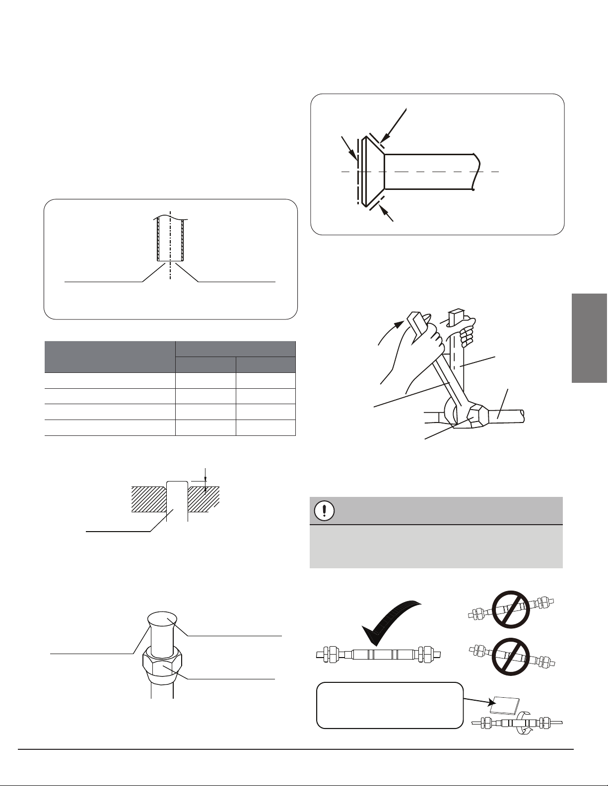
Outer diam. A
Max. Min
1/4 in 1.3 0.7
3/8in 1.6 1.0
1/2in 1.8 1.0
5/8in 2.2 2.0
5.1 Flaring the pipe end
1. Cut the pipe end with a pipe cutter.
2. Remove burrs with the cut surface facing
downward so that the chips do not enter
the pipe. See Fig 5.3.
3. Put the are nut on the pipe.
4. Flare the pipe. Set exactly at the position
shown in Fig 5.5.
5. Check that the aring is properly made.
5.2 Refrigerant Piping
1. Use Nylog or similar approved refrigerant
sealant.
4.3 Install refrigerant pipe adapter. (if needed)
2. Align the centers of both ares and
tighten the are nuts 3 or 4 turns by hand.
Then tighten them fully with the torque
wrenches.
Cut exactly at
right angles Remove
burrs
Fig 5.3
Fig 5.6
Fig 5.4
Fig 5.5
Fig 5.7
Fig 5.8
Die
Copper pipe
A
Set exactly at the position shown below
Flare's inner surface
must be flaw-free
Make sure that the
flare nut is fitted.
The pipe end must
be evenly flared in a
perfect circle.
Coat here with Nylog
Spanner
Piping
Union
Torque
wrench
Flare nut
Page 13
Revised 5/14/2020
Mount the refrigerant adapter as horizontally
as possible. See Fig. 5.8.
CAUTION
Indoor
Indoor
Indoor
Outdoor
Outdoor
Outdoor
Wrap the supplied anti-shock
rubber around the throttle
to reduce noise.
Refrigerant Piping
Installation
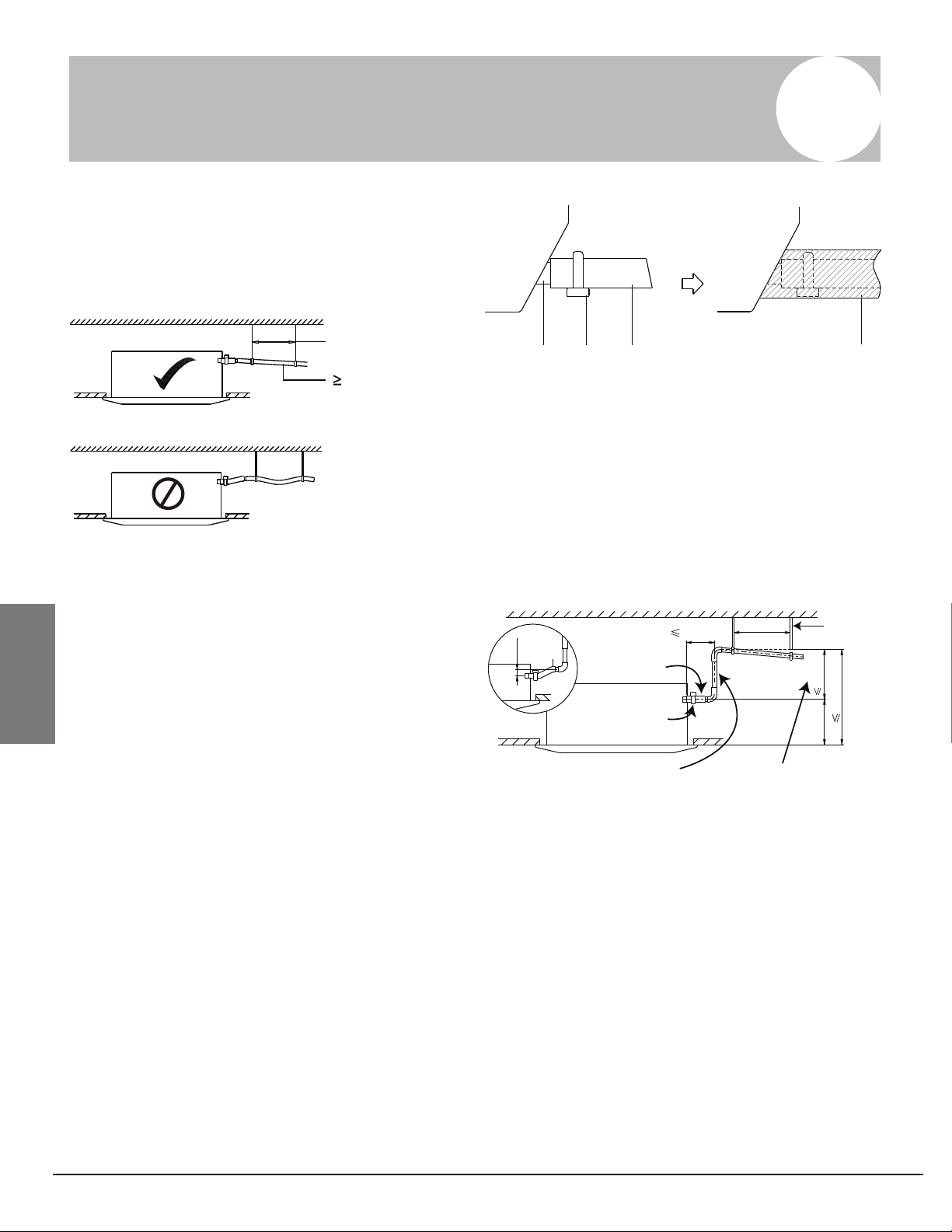
6.1 Installation of drain piping
Install the drain piping as shown in gure below
and take measures against condensation.
Use PVC pipe, use of plastic, exible piping is
discouraged.
6.3 How to perform piping
• Connect the drain hose to drain lift pipes, and
insulate them.
• Connect the drain hose to the drain outlet on
the indoor unit, and tighten it with the clamp.
6.2 Install the drain pipes
• Keep piping as short as possible and slope it
downwards at a gradient of at least 1/100 so
that air may not remain trapped inside the
pipe.
• Keep pipe size equal to or greater than that of
the discharge pipe of the unit.
• Push the drain hose as far as possible over
the drain socket, and tighten the metal clamp
securely.
• Insulate the drain hose inside the building.
• If the drain hose cannot be suciently set on
a slope, t the hose with drain lift piping (eld
supply).
• Make sure that heat insulation work is
executed on the Indoor drain pipe and the
drain socket to prevent condensation.
3~5ftHanging bar
1/100 gradien
t
Fig 6.1
12
34
1 - Drain socket (attached to the unit)
2 - Metal clamp
3 - Drain hose
4 - Insulation (field supply)
Fig 6.3
5
11.8in
8.7in
29.5in
0~3in
20.9in
3~5ft
Ceiling Slab
Hanger
bracket
Adjustable
range
Drain
raising pipe
Metal
clamp
Drain
hose
Page 14 Revised 5/14/2020
6
Connecting The Drain Pipe
Connecting
The Drain Pipe
6.4 Test the drain piping
After the piping work is nished, check if drainage
ows smoothly.
When electric wiring work is nished, check
drainage ow during COOL running, explained in
"Test operation".
Fig 6.4 Fig 6.5
CAUTION
• Install the drain lift pipes no higher than 21".
• Install the drain lift pipes at a right angle to the indoor unit and no more than 12" from the unit.
• To prevent air bubbles, install the drain hose level.
• The incline of drain hose should be no more than 3"so that the drain socket does not have to
withstand additional force.
• To ensure a downward slope of 1:100, support the drain line every 3'.
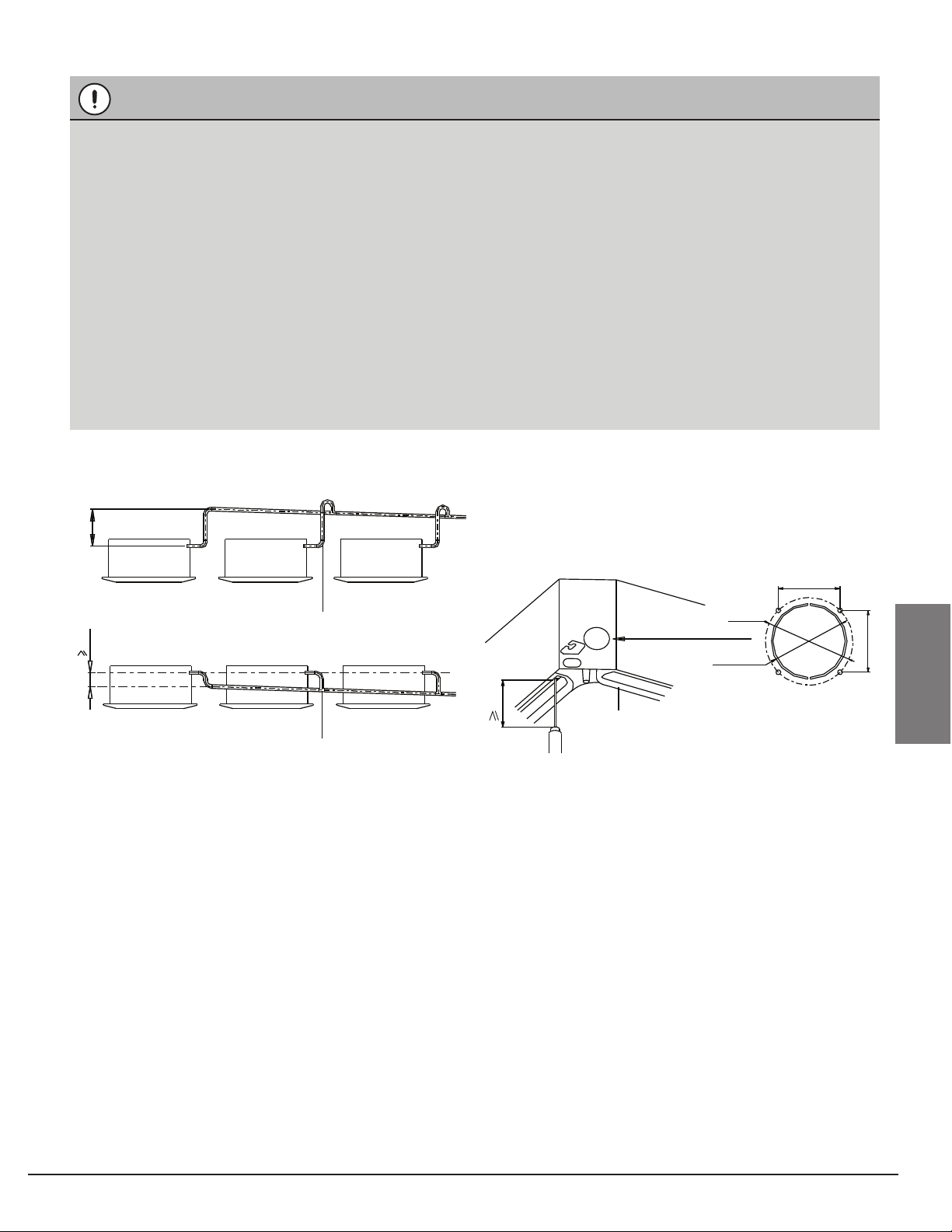
• When unifying multiple drain pipes, install the pipes as shown in gure below. Select
converging drain pipes whose gauge is suitable for the operating capacity of the unit.
• Do not connect the drain piping directly to sewage pipes that smell of ammonia. The
ammonia in the sewage might enter the indoor unit through the drain pipes and corrode the
heat exchanger.
0-530
100
T-Joint converging drain pipes
T-Joint converging drain pipes
Unit
: mm
3.9in
Fresh air intake 2.6i
n
3in
2.6in
4.2in
4.2in
Water
receiver
Page 15
Revised 5/14/2020
Connecting
The Drain Pipe
CAUTION
• All eld wiring and components must be installed by a licensed electrician and must comply with
relevant European and national regulations.
• Use copper wire only.
• Follow the 'Wiring diagram' attached to the unit body to wire the outdoor unit, indoor units and
the remote controller.
• A circuit breaker capable of shutting down power supply to the entire system must be installed.
• Note that the operation will restart automatically if the main power supply is turned o and then
turned back on again.
• Be sure to ground the air conditioner.
• DO NOT connect the ground wire to gas pipes, water pipes, lightning rods, or telephone ground
wires.
• Gas pipes: might cause explosions or re if gas leaks.
• Water pipes: no grounding eect if hard vinyl piping is used.
• Telephone ground wires or lightning rods: might cause abnormally high electric potential in the
ground during lightning storms.
7
Electrical Wiring
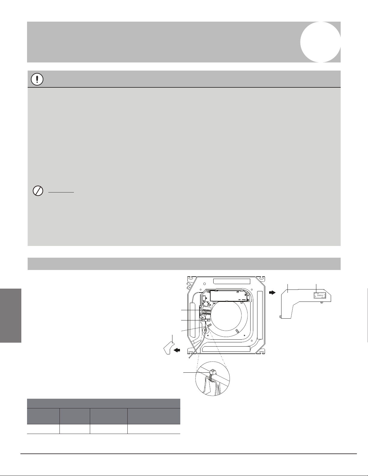
How to connect wiring
• Remove the control box lid of the
indoor unit.
• Remove the cover of the outdoor unit.
• Follow the "Wiring diagram label"
attached to the indoor unit's control
box lid to wire the outdoor unit, indoor
unit and the remote control. Securely
x the wires with a eld supplied
champ.
• Attach the cover of the outdoor unit.
12
4
5
6
3
7
1 Control box lid
2 Wiring diagram label
3 Power supply terminal block
4 Clamp for wiring
5 Wiring between units
6 Plastic cover
7 Clamp (field supply)
Fig 7.1
Power
Model Phase Frequency
and volt
Circuit breaker/
Fuse(A)
12K~18K 1Phase 208-240V 20/16
Page 16 Revised 5/14/2020
Electrical
Wiring

8
Decorative Panel Installation
Fig 8.1
Fig 8.3
Fig 8.6
Fig 8.7
Fig 8.8
Fig 8.4
Fig 8.2
Detach the intake grille
Slide the 2 grille hooks toward the
middle of the decoration panel.
Mount the intake grille
After installing the decoration panel, ensure that
there is no space between the unit body and
decoration panel. Otherwise air may leak through
the gap and cause dewdrop. See gure below.
Install the decoration panel
• Align the indicate " " on the decoration panel
to the indicate " " on the unit .
• Attach the decoration panel to the unit with
the supplied screws as shown in gure below.
1 - Intake grille
2 - Grille hook
Ensure that the grille is
properly seated in the
groove of the panel.
Fasten the control box
lid with 2 screws.
Connect the 2 wires
of the decoration
panel to the main
board of the unit.
Leave third wire plug
detached.
Close the intake
grille, and close the
2 grille hooks.
Open the intake
grille and remove
1 - Decoration panel
2 - Screws (M5) (supplied with the panel)
1
2
1
2
10-cor
e wire
5-core
wire
Page 17
Revised 5/14/2020
Decorative Panel
Installation

The design and specications are subject to change without
prior notice for product improvement.
AlpineHomeAir.com
Revised 5/14/2020
Install Outdoor Unit
(see separate manual)
When you have nished installing all indoor air handlers, proceed to installation of the outdoor unit.
Complete installation instructions and startup procedures are given in the outdoor unit installation
manual. Copies are always available at AlpineHomeAir.com by searching your unit's model number
and scrolling to Documents.
This manual suits for next models
1
Table of contents
Other Blue Ridge Fan manuals


