Juwent WD-16 User manual

ROOF FANS
WD
Szymański, Nowakowski General Partnership
31 Lubelska Str., 08-500 Ryki
phone +48 81 883 56 00, fax +48 81 883 56 09
POLAND
I. CONTACTS
II. ORIGINAL INSTRUCTION MANUAL
III. WARRANTY TERMS AND CONDITIONS
IV. UNIT STARTUP REPORT
V. INSPECTION AND MAINTENANCE DOCUMENT
VI. SERVICE NOTIFICATION
VII. LIST OF SUBASSEMBLIES INSTALLED IN THE UNIT
Please read this instruction manual carefully before beginning any work.
RYKI 2015
ISSUE 1 EN

2www.juwent.com.pl
I. CONTACTS
Szymański, Nowakowski General Partnership
31 Lubelska Str., 08-500 Ryki
POLAND
phone +48 81 883 56 00,
fax +48 81 883 56 09
www.juwent.com.pl
Export department
mob.+48 502 087 841
mob.+48 664 465 243

3www.juwent.com.pl
ROOF FANS
WD size 16 to 40
II. ORIGINAL INSTRUCTION MANUAL

4www.juwent.com.pl
TABLE OF CONTENTS
1. INTENDED USE 5
2. DEVICE DESCRIPTION 5
3. DESIGNATIONS 5
5. TECHNICAL DATA 6
6. ADDITIONAL EQUIPMENT 7
7. TRANSPORT 10
8. SAFETY RECOMMENDATIONS 10
9. INSTALLATION 11
10. ELECTRICAL INSTALLATION 11
11. AUTOMATION ELEMENTS 14
12. DEVICE COMMISSIONING 15
13. REPAIR, MAINTENANCE AND WITHDRAWAL FROM USE 15
14. REMOVING MALFUNCTIONS 16
15. INFORMATION 16

5www.juwent.com.pl
1. INTENDED USE
The roof fans are used for the removal of air from production halls, warehouses, commercial
pavilions etc. They are intended for the use in special conditions where air contains toxic or highly
caustic media.
The fans can also be used for the replacement of the fans operating earlier in the ventilation systems
or using subassemblies as spare parts.
The air being removed by the fan should not have humidity greater than 90% and dust
content above 5mg/m3. The temperature of the air being removed cannot be more than
55OC.
Use of the fans in explosion-hazard atmosphere is not admissible.
The fans are suitable for operation with impeller vertical rotation axis, and the air is being removed
in the vertical direction.
The fans are adapted for mounting on universal roof bases, damping roof bases.
2. DEVICE DESCRIPTION
The series of the roof fans contains 5 sizes.
The fans include:
»» highly-efcient centrifugal steel impeller;
»» electric motor;
»» bearing plate, body and cover made of glass-bre laminate.:
Impeller of the roof fan could be made of acidproof steel.
3. DESIGNATIONS
Roof fan WD-25 -TD900/1400 -K
Size 16, 20, 25, 31,5, 40
Motor type
three-phase two speed TD-[900/1400rpm for sizes 16; 20; 25; 31,5]
three-phase single speed T-[700 or 900rpm for size 40]
single-phase J-[900 or 1400rpm for sizes 16; 20; 25; 31,5]
single-phase J-[700 or 900rpm for size 40]
Acidproof version of fan impeller

6www.juwent.com.pl
5. TECHNICAL DATA
Fan type Ød
[mm]
ØD1
[mm]
ØD
[mm]
H
[mm] n Weight [kg]
WD-16 140 190 500 400 4 16
WD-20 170 230 500 400 4 15
WD-25 220 280 605 470 6 17
WD-31,5 265 345 605 510 6 25
WD-40 360 430 810 660 8 38
Ambient parameters for the fan and the motor (for all sizes)
Air temperature range Max. air humidity Max. dust content Motor parameters
IP Insulation class
do + 50OC90% 5 mg/m354 F
Fan operating noise level
Fan type Speed [rpm]
Noise level [dB(A)]
at the air outlet side* at the air inlet side**
at the distance
of 1m
at the distance
of 5m
at the distance
of 1m
at the distance
of 5m
Three-phase two speed motors
WD-16 940 54 42 50 45
1400 63 51 59 54
WD-20 940 56 44 52 47
1400 65 53 61 56
WD-25 940 58 46 54 49
1400 67 55 63 59
WD-31,5 960 62 50 58 53
1390 70 58 66 61
Three-phase single speed motors
WD-40 700 65 53 61 56
900 70 58 66 61
*Operating noise level in dB(A) -– acoustic pressure level at the air outlet side, in the free eld with
taking into consideration the directional factor Q=2 and at the distance of 1 and 5m from the fan.
** Operating noise level in dB(A) – acoustic pressure level at the air inlet side with taking into
consideration the accommodation absorption ability of the compartment A=100m2, directional
coefcient Q=2 and from distance of 1 and 5m from the air inlet to the fan.

7www.juwent.com.pl
Fan operating noise level
Fan type Speed [rpm]
Noise level [dB(A)]
at the air outlet side* at the air inlet side**
at the distance
of 1m
at the distance
of 5m
at the distance
of 1m
at the distance
of 5m
Single-phase motors
WD-16 940 54 42 50 45
1420 64 52 60 55
WD-20 940 56 44 52 47
1420 66 54 62 57
WD-25 940 58 46 54 49
1420 68 56 64 59
WD-31,5 900 63 51 59 54
1420 72 60 67 62
WD-40 700 66 54 62 57
900 71 59 67 62
*Operating noise level in dB(A) -– acoustic pressure level at the air outlet side, in the free eld with
taking into consideration the directional factor Q=2 and at the distance of 1 and 5m from the fan.
** Operating noise level in dB(A) – acoustic pressure level at the air inlet side with taking into
consideration the accommodation absorption ability of the compartment A=100m2, directional
coefcient Q=2 and from distance of 1 and 5m from the air inlet to the fan.
6. ADDITIONAL EQUIPMENT
For roof fans WD additional equipment can be delivered:
»roof bases;
»additional elements;
Roof fan WD mounted on PWD roof base
Fan type Roof base size Additional elements
Silencer Self-closing damper Inlet diffuser
WD-16 PWD-16 TWD-16 SWD-16 DW-16
WD-20 PWD-20 TWD-20 SWD-20 DW-20
WD-25 PWD-25 TWD-25 SWD-25 DW-25
WD-31,5 PWD-31,5 TWD-31,5 SWD-31,5 DW-31,5
WD-40 PWD-40 TWD-40 SWD-40 DW-40

8www.juwent.com.pl
THE ADDITIONAL EQUIPMENT LISTING FOR THE WD ROOF FANS MOUNTED ON PWD BASES
F- roof fan PWD / PWD PLUS - roof base
c - ceiling SWD / SWD PLUS - self-closing damper
TWD / TWD PLUS - silencer DW / DW PLUS - inlet diffuser
Roof base PWD
Typ B/I Typ B/II Typ B/III
Roof base
size
A
[mm]
Ød
[mm]
Ød1
[mm] nxØ10 H
[mm]
L
[mm]
L1
[mm]
H1
[mm]
PWD-16 340 160 190 4 125 590 675 75
PWD-20 390 200 230 4 125 590 675 75
PWD-25 450 250 280 6 125 590 675 75
PWD-31,5 535 315 345 6 150 790 900 100
PWD-40 640 400 430 8 150 790 900 100

9www.juwent.com.pl
Roof fan WD mounted on PU or PUT universal roof base
Fan type Roof base size Roof base
Additional elements
Assembly
plate
Self-closing
damper
Inlet
diffuser
Flexible
connector
WD-16 PU-1 PUT-1 PWDt-1 PM-1 SWD-1 DW-1 KEO-1
WD-20 PU-2 PUT-2 PWDt-2 PM-2 SWD-2 DW-2 KEO-2
WD-25 PU-3 PUT-3 PWDt-3 PM-3 SWD-3 DW-3 KEO-3
WD-31,5 PU-4 PUT-4 PWDt-4 PM-4 SWD-4 DW-4 KEO-4
WD-40 PU-5 PUT-5 PWDt-5 PM-5 SWD-5 DW-5 KEO-5
F- roof fan PWDt - roof base
PU - roof base PUT - noise damping roof base
PM - assembly plate c - ceiling
SWD - self-closing damper KEO - exible connector
DW - inlet diffuser s - ventilation system duct
PU roof base
Fan type Base size A
[mm]
B
[mm]
C
[mm]
H
[mm] Weight [kg]
WD-16 PU-1 360 330 662 300 9
WD-20 PU-2 412 380 712 300 10,5
WD-25 PU-3 452 420 752 300 11
WD-31,5 PU-4 512 480 812 300 12,5
WD-40 PU-5 592 560 892 300 14,5

10 www.juwent.com.pl
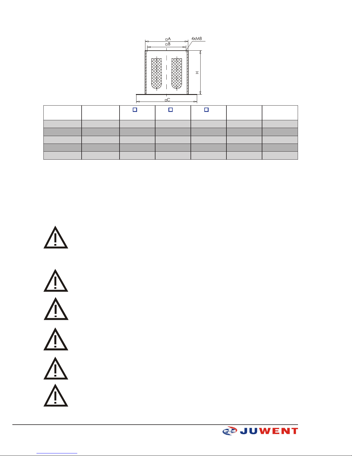
PUT noise damping roof base
Fan type Base size A
[mm]
B
[mm]
C
[mm]
H
[mm] Weight [kg]
WD-16 PUT-1 360 330 662 700 22,5
WD-20 PUT-2 412 380 712 700 25,5
WD-25 PUT-3 452 420 752 700 27,5
WD-31,5 PUT-4 512 480 812 700 30,5
WD-40 PUT-5 592 560 892 900 49
Efciency of universal base noise damping is in the A scale ~14dB(A).
7. TRANSPORT
Fans are delivered as completely assembled, protected against pollutions and weather with
polyethylene foil or cartboard box.
The fan is delivered with the Product Book.
The PU and PUT roof bases are additional equipment and are delivered separately protected with
polyethylene foil.
The fans should be transported on one level so as to prevent any mechanical damages.
8. SAFETY RECOMMENDATIONS
Roof fans should be used in accordance with the operation manual.
Installation, connection, commissioning, inspection and repair works on the fans should
be performed by an authorised technician, and electrical works by a person holding the
required qualications.
All maintenance and repair works should be carried out with voltage off
In the case of the fan failure immediately turn the motor electrical power supply off.
The fan can only work with properly operating electrical protection devices. It must be
uninterruptedly connected to the electrical installation tted with protection terminal,
residual-current device and service switch.
Use original spare parts only.

11www.juwent.com.pl
Due to its design, the device does not emit any hazardous radiation.
Despite the fact that the device has been designed and manufactured in accordance with the
standards valid as for the moment of the manufacture start, probability of injury and damage
to health when using the device is unavoidable. This probability is related to frequency of using,
cleaning and repairing the device, presence of persons within the danger area, and not respecting
the safety rules as set out in the instruction.
Severity of the bodily injury and deterioration of health is dependant on numerous conditions which
can be foreseen partially only by considering them when designing the device and by providing
descriptions and warnings in the instruction manual.
Therefore residual risk is present if recommendations and instructions are not respected by the
operator.
9. INSTALLATION
The fans are bolted trough seals on roof bases, ventilation ducts or damping roof bases with use of
M8 bolts (4, 6 or 8 pcs. depending on size of roof fan).
The support plate of roof fan is equipped with laminaded nuts for bolting with spring washers.
The fans should be installed upright.
Installation of the fan and additional equipment should conform to the construction
design covering the manner of placing and the fan whilst taking into consideration
strength of the roof structure and tightness of the roong.
Connection ducts ate the fan suction side should have their own supports and
mountings.
Roof fans mounted on silencers over the roof and ventilation ducts need to perform
adequately durable support structure.
10. ELECTRICAL INSTALLATION
Connections of electrical installation and power supply to the fans must be carried out in accordance
with relevant construction standards and regulations.
Electrical connections to the fans can only be carried out by an authorized electrician
familiar with the instruction manual.
Before connecting make sure that the voltage and frequency rating of the power supply are in
accordance with the data given on the fans data plates. Otherwise, do not connect the device.
The fans are equipped with three-phase (3~400V/50Hz) or single-phase motors (1~230V/50Hz)
which should be power-supplied with the voltage from the main switchgear tted with main circuit-
breaker and differential protection. The electrical connection of the fan itself should be carried out
taking into account the service switch located directly by the fan, as well as the overload and short-
circuit protection inside the power supply/control box.
Warning! Make sure to provide the required motor protections, otherwise the warranty is
void.
Insert the power cord of the fan motor into the terminal box and x it on protective grate or supports
of the fan with cable ties.
Electrical connection of the motor must be in accordance with electrical diagrams provided in the
terminal box.
Example of electrical diagrams - Fig. 1 to 4.

12 www.juwent.com.pl
DESIGNATIONS FOR DIAGRAMS:
PT - Motor overcurrent protection
K - Contactor
PZ - Control button ON
PW - Control button OFF
B, BS - Fuses
WS - Service switch
Fig.1 Example electric connnection diagram of WD16-TD, WD20-TD, WD25-TD; WD31,5-TD fans
with two speed three phase motors (Y/Y connection).
DESIGNATIONS FOR DIAGRAMS:
PT - Motor overcurrent protection
K - Contactor
PZ - Control button ON
PW - Control button OFF
B, BS - Fuses
WS - Service switch
Fig. 2 Example electric connnection diagram of WD-40-T with single speed three phase motors (only
star connection).

13www.juwent.com.pl
DESIGNATIONS FOR DIAGRAMS:
PT - Motor overcurrent protection
K - Contactor
PZ - Control button ON
PW - Control button OFF
B, BS - Fuses
WS - Service switch
Fig. 3 Example electric connnection diagram of WD roof fans with single phase motors.
Fig. 4 Example electric connnection diagram of WD roof fans with single phase motorsrotów and
TR speed controller.

14 www.juwent.com.pl
11. AUTOMATION ELEMENTS
The fan can be tted with the following:
1. Power supply/control boxes
Hermetically enclosed for surface mounting, (equipped with: main switch, overcurrent and short-
circuit breakers, signal lamps and speed selectors). The boxes should be mounted on a wall in a
location from where the devices can be operated easily.
The power supply 3~400V/50Hz or 230V/50Hz of the power supply/control box should be delivered
by the main switchgear tted with main circuit-breaker and differential protection.
In the case of an order including the delivery of the fans tted with the box, additional electrical
diagram for the fans and the box are also supplied.
2. TR Speed Controller
TR Speed Controller is used for stepless speed control of single-phase WD-16-J, WD-20-J, WD-
25-J, WD-31,5-J roof fans. Electric connections diagrams of WD roof fans with or wihout TR speed
controller are shown at g. 3 and 4.
Before starting the fan, control knob must be set in the far right position. When you turn on the fan,
wait about 20 seconds (to obtain the maximum motor speed), then you can set the desired speed.
TR speed controller parameters
Supply voltage 230V
Regulated load voltage 90…230V
Continuous load current 5A
Load power 500 W
Slow blow fuse 5 A
Power switch 2-step
3. WS serwice switch
WS service switch is used to switch the fan motor off for the period of servicing and maintenance.
The WS service switch is a safety element that prevents the fan motor from accidental switch-on
during in the course of servicing and maintenance
WS serwice switch parameters
Type WS-3 WS-6
Poles 3-poles 6-poles
Supply voltage cirquit switch single and three phase three phase
Rated continuous current 25A 25A
Protection level IP65 IP65

15www.juwent.com.pl
12. DEVICE COMMISSIONING
Commissioning of the fan should be carried out by properly qualied personnel only. Before the
commissioning check the following:
»the fan for correct mounting,
»the electrical connection for correct execution according to electrical diagram,
»the enclosure for the presence of any foreign particles,
»the impeller for free rotation without rubbing the fan inlet funnel.
Turn the fan on for few seconds and observe the direction of rotation to check compliance of the fan
rotor rotation direction of with the direction indicated by arrow on the cover of the fan.
Once the above works are completed, turn the fan on and observe if there is no vibrations and
noise emitted by the impeller. Moreover, during the rst commissioning of the fan it is advisable to
measure the starting current consumed by the motor. If the current is lower than the rated current,
the fan can be considered t for further use.
If any problems and disturbances arise during the commissioning, switch the power off
and contact the supplier or the JUWENT service department.
13. REPAIR, MAINTENANCE AND WITHDRAWAL FROM USE
The fans are intended for continuous operation.
At least once a year check the condition of the fan motor (the motor bearings require no regular
lubrication) and, if necessary, remove the defects found according to the motor manufacturer
instructions.
Depending on the degree of air pollution, and no less than once a year, clean the fan impeller from
any dust and dirt.
Fan bodies in the lower part are equipped in the outow holes. You should check and if necessary
clean above holes.
All maintenance and repair works should be carried out with voltage off.
Use of high-pressure washers is not admissible.
Once the device is withdrawn from use, handle it to a proper waste treatment plant

16 www.juwent.com.pl
14. REMOVING MALFUNCTIONS
Description of
malfunction Possible causes of malfunction Measures of prevention/removal
Fan won’t work
Incorrect connection to power supply Check for proper connection to power supply.
Locked impeller Remove cause of locking
Damaged motor Report at JUWENT service department
Low fan perfor-
mance
Incorrect impeller rotational direction (not in accor-
dance with marking on fan enclosure) Change polarity of power supply connection
Contaminated fan inlet grate Clean inlet grate
Fan high vibrations
Incorrect fan - roof base or roof base - fan connec-
tion. Check for correct connections
Contaminated or damaged impeller
Remove impeller contaminations.
Report any impeller damages at JUWENT service depart-
ment
Fan operates
with excess noise,
knocks
Plays on connections between fan elements or on
connection between fan and roof base
Remove plays on connections by tightening bolts and
screws
Rubbing between impeller and enclosure Report at JUWENT service department
Damaged motor bearings
Activation of mo-
tor overload pro-
tections
Damaged or worn bearings.
Damaged motor windings (break, overheat).
Damaged circuit-breaker or protection system.
Report at JUWENT service department
Incorrectly set protection relay.
Loss of one of supply phases Check electrical installation and protection systems
15. INFORMATION
As to all issues concerning the roof fan please contact JUWENT Production Plant or our Representatives

17www.juwent.com.pl
III. WARRANTY TERMS AND CONDITIONS
1. JUWENT Szymański, Nowakowski General Partnership, headquartered in Ryki at 31 Lubelska Str., hereinafter referred to as the
Warrantor, grants the Customer a warranty of proper operation of the unit with reservation of the requirement of its use in accordance
with the conditions determined in the instruction manual and the terms and conditions specied below.
2. The warranty has been granted for a period of 24 months from the purchase date demonstrated in this warranty document with
a possibility of its special extension according to a separate agreement and specied in the Special Warranty Terms and Conditions.
3. The warranty covers the removal of technical defects of the unit arisen as a result of its use in accordance with the instruction
manual, revealed within the warranty period. The warranty provisions are valid in the territory of the Republic of Poland.
4. By virtue of the granted warranty the Warrantor is not liable for the loss of expected prots and costs resulting from a periodical
impossibility of the use of the unit incurred by the Customer.
5. To realize the Customer’s rights resulting from the warranty it is required to deliver the claimed unit with the warranty document
to the Warrantor at his expense.
6. The claimer delivers the unit in an original factory packing, in case there is no factory packing the claimed unit should be delive-
red by the Customer for the repair in a way ensuring a safe transport. The risk of accidental damage of the unit during the transport
burdens always the party that dispatches the parcel.
7. The defects revealed with the warranty period will be removed by the Warrantor free of charge. A method selection of the reali-
zation of obligations resulting from the warranty granted to the Customer belongs to the Warrantor that may remove a defect by the
repair or the replacement of the damaged subassembly or by the replacement of the unit. The property of the unit withdrawn from
service and / or defective subassemblies is transferred to the Warrantor.
8. The warranty is extended by a period for which the Customer has been deprived of a possibility to use the unit.
9. The Warrantor will make efforts that the repair is executed without further delay within the time-limit of up to 14 working days
from the delivery date of the unit. In reasonable cases of which the Customer will be informed by the Warrantor, this time-limit may
be extended, e.g. by the time of provision import or when there is a necessity to execute an expertise or laboratory tests in specialized
institutions.
10. The Warrantor is liable exclusively for the defects inherent in the sold unit. The damages arisen after its sale for other reasons are
not covered by the warranty, in particular:
a) mechanical damages (including also damages caused by microparticles occurring in the working environment of the unit),
thermal damages, chemical damages and aleatory damages or damages caused by the atmospheric factors,
b) damages occurred as a result of non-observance of typical rules or the rules required by the instruction manual related to the
operation and mounting of the unit or the use of the unit against the intended use and other damages caused by the Customer’s
activity or omission,
c) damages being a result of defective operation of the system in which the unit has been built or used,
d) damages occurred as a result of non-execution of the actions to which the Customer has been obliged in accordance with the
instruction manual, e.g. periodical cleaning, maintenance, adjustment, etc.,
e) damages occurred due to the use of materials or parts subject to a normal operational wear other than the materials recom-
mended by the Warrantor in the instruction manual,
f) damages being a result of use of power supply of the unit (of the system in which this unit functions) incompliant with the
standard, and in case the unit is also supplied with water, damages being a result of use of water (supply water and / or boiler
water) with parameters other than the parameters foreseen in the valid standard (PN-93/C-04607),
g) damages occurred as a result of operation and / or maintenance of the unit in a way incompliant with the instruction manual
and / or executed by the unauthorized persons.
11. The warranty does not cover as well:
a) activities executed by the Customer in accordance with the recommendations included the instruction manual of the unit within
the framework of normal maintenance and inspections,
b) travel and work costs of the Warrantor’s service or an entity delegated by the Warrantor in case when a warrant call turns out
to be groundless.
12. An annotation made by a trained employee in the Inspection and Maintenance Document of the unit is a conrmation of time-
-limit holding and range of activities foreseen for the maintenance of the unit.
13. The Warrantor is not liable for damages incurred by the Customer or third parties caused the run of the unit occurred in particular
as a result of non-observance of the afore-mentioned terms and conditions by the Customer.
14. In case the service works are executed by the Warrantor at the place where the unit is mounted, the Customer will make available
a free access to the rooms where the units are located to the Warrantor.
15. In case the units are mounted at the height making an access from the oor surface impossible, the Customer will ensure the
scaffolding compliant with the OHS regulations or mobile lifting platforms and vertical transport equipment.
16. The equipment from the electric and / or hydraulic system is disassembled by the Customer.
17. The claims should be lodged at the Warrantor’s address in writing / by fax / email using a service notication form.
18. The Warrantor refuses to execute the warranty activities (periodical service works or repair) in case the price for the unit or pre-
vious service work is not paid for the benet of the Warrantor.
DATE OF SALE STAMP AND SIGNATURE
Special Warranty Terms and Conditions:
Warranty period extension up to ........... months.
Other:
STAMP AND SIGNATURE

18 www.juwent.com.pl
TYPE OF UNIT:
FACTORY NUMER:
YEAR OF PRODUCTION:
IV. UNIT STARTUP REPORT
Date of
startup
Executor of startup
stamp / name and signature
Motor
current
[A]
User’s representative
stamp / name and signature Remarks
V. INSPECTION AND MAINTENANCE DOCUMENT
Date of
inspection
Executor of inspection
stamp / name and signature Service activity range Remarks
* Inspection of the unit in accordance with the section “Repair and Maintenance” in the instruction manual

19www.juwent.com.pl
VI. SERVICE NOTIFICATION
Date:
Notication type WARRANTY POST-WARRANTY PAID
Unit’s user (name)
Contact person
User’s address
Phone, fax. and email
Type of unit
Factory No.
Year of production
Startup executed by
Description of defect:
NOTE: AFTER COPYING AND FILLING IN SEND THE NOTIFICATION BY FAX OR EMAIL TOGETHER WITH A
COPY OF THE STARTUP REPORT.
JUWENT Company accepts notications lled legibly and completely.
When the lodged claim is not justied, the claimer will be burdened with service costs.
Date of warranty issue Order No. (company’s stamp)
......................................................... ...........................

20 www.juwent.com.pl
VII. LIST OF SUBASSEMBLIES INSTALLED IN THE UNIT
No. Name of subassembly *)
1Impeller in standard version
2 Impeller in acidproof steel version
3Three phase single speed fan motor
4 Three phase two speed fan motor
5 Single phase fan motor
*) - mark proper box corresponding with the equipment variant
This manual suits for next models
4
Table of contents
Other Juwent Fan manuals
Popular Fan manuals by other brands

Airius
Airius RETAIL R20/EC PRODUCT INFORMATION & INSTALLATION GUIDE

BVN
BVN BPR 1012 User manual & certificate of warranty

HighPoint
HighPoint SSD7101A-1 Quick installation guide

Goobay
Goobay 52718 user manual

enervent
enervent Salla eAir installation instructions

lobal Product Resources
lobal Product Resources DECO BREEZE instruction manual