Blue Sea EVOLUTION G47 User manual
Blue Seal Evolution Series - G47 Gas Pasta Cooker © Copyright Moffat Ltd, March 2016
Amendment 6
Service Manual
Pasta Cookers
G47

Blue Seal Evolution Series - G47 Gas Pasta Cooker © Copyright Moffat Ltd, March 2016
Amendment 6
ALL INSTALLATION AND SERVICE REPAIR WORK MUST BE CARRIED OUT BY QUALIFIED PERSONS
ONLY.
WARNING:
MAKING ALTERATIONS MAY VOID WARRANTIES AND APPROVALS.
IMPORTANT:

Blue Seal Evolution Series - G47 Gas Pasta Cooker © Copyright Moffat Ltd, March 2016
Amendment 6
This manual is designed to take a more in depth look at the G47 Pasta Cookers for the purpose of making the units more
understandable to service people.
There are settings explained in this manual that should never require to be adjusted, but for completeness and those special cases
where these settings are required to change, this manual gives a full explanation as to how, and what effects will result.
Section Page No.
1. Specifications ........................................................................................................................... 3
2. Installation ............................................................................................................................... 5
3. Operation ................................................................................................................................ 10
3.1 Description of Controls
3.2 Explanation of Control System
4. Maintenance ........................................................................................................................... 12
5. Fault Finding Guide ................................................................................................................ 13
5.1 Fault Finding Chart
5.2 Fault Diagnosis
6. Service Procedures ................................................................................................................. 16
6.1 Access
6.2 Replacement
6.3 Adjustment / Calibration
7. Accessories ............................................................................................................................. 21
Gas Conversion Kits
Accessories
8. Exploded Parts Diagrams ...................................................................................................... 22
9. Circuit Schematics .................................................................................................................. 28
10. Service Contacts ..................................................................................................................... 29
Appendix A: Gas Type Conversion .................................................................................................. 30
Appendix B: Gas Specifications ...................................................................................................... 32
Contents

Blue Seal Evolution Series - G47 Gas Pasta Cooker © Copyright Moffat Ltd, March 2016
Amendment 6

3
1
Specifications
Blue Seal Evolution Series - G47 Gas Pasta Cooker © Copyright Moffat Ltd, March 2016
Amendment 6
Dimensions shown in millimetres.
Legend
- Gas connection entry point - ¾” BSP male
External Dimensions: G47
4
1
Specifications
Blue Seal Evolution Series - G47 Gas Pasta Cooker © Copyright Moffat Ltd, March 2016
Amendment 6
Model Numbers Covered in this Specification
G47 Pasta Cooker (Single Tank - 40 Ltr).
Gas Supply Requirements
- Australia:
- New Zealand:
- UK Only:
Category: II2H3P.
Flue Type: A1.
NOTE: (*) Measure burner operating pressure at upper test point (Supply Pressure) on gas control valve located behind
control panel, this is to be carried out with burner operating at ‘High Flame’ setting. Refer to ‘Gas Conversion
and Specification’ Section for further details.
- All Other Markets:
NOTE:
(*) Measure burner operating pressure at upper test point (Supply Pressure) on gas control valve located
behind control panel, this is to be carried out with burner operating at ‘High Flame’ setting.
NAT, LPG & Butane Only - Operating pressure is ex-factory set and is not to be adjusted, apart from when
converting between gasses, if required.
TOWN GAS Only - Burner operating pressure is to be adjusted using adjustable gas regulator supplied.
(**) Town Gas Option is only available with specific ex-factory built Town Gas models, which can also be
converted to any other gas. Standard models can only be converted between Nat. Gas, LP Gas and Butane,
but not Town Gas.
Refer to ‘Gas Conversion and Specifications' section in this manual for further details.
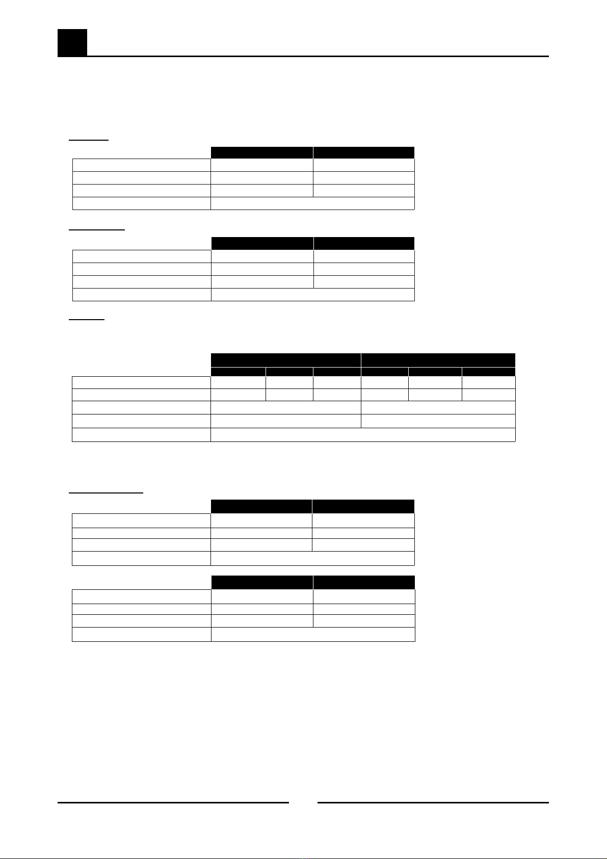
Natural Gas (G20) Propane (G31)
Nominal Reduced Pilot Nominal Reduced Pilot
Heat Input (nett) 12.0 kW 5.4 kW 320W 12.5 kW 6.2 kW 320W
Gas Rate 1.27 m3/hr 0.42 m3/hr 0.03 kg/hr 0.97 kg/hr 0.48 kg/hr 0.02 kg/hr
Supply Pressure 20 mbar 37 mbar
Burner Operating Pressure (*) 27.7 mbar
Gas Connection 3/4” BSP Male
9.5 mbar
Natural Gas LP Gas
Input Rating (N.H.G.C.) 46 MJ/hr 47 MJ/hr
Supply Pressure 1.13 - 3.40 kPa 2.75 - 4.50 kPa
Burner Operating Pressure (*) 0.92 kPa 2.6 kPa
Gas Connection ¾” BSP Male
Natural Gas LP Gas / (Propane)
Input Rating (N.H.G.C.) 46 MJ/hr 47 MJ/hr
Supply Pressure 1.13 - 3.40 kPa 2.75 - 4.50 kPa
Burner Operating Pressure (*) 0.92 kPa 2.6 kPa
Gas Connection ¾” BSP Male
Natural Gas Town Gas (**)
Input Rating (N.H.G.C.) 46 MJ/hr 47 MJ/hr
Supply Pressure 1.13 - 3.40 kPa 0.75 - 1.5 kPa
Burner Operating Pressure (*) 0.92 kPa 0.5 kPa
Gas Connection ¾” BSP Male
LP Gas (Propane) Butane
Input Rating (N.H.G.C.) 47 MJ/hr 47 MJ/hr
Supply Pressure 2.75 - 4.50 kPa 2.75 - 4.50 kPa
Burner Operating Pressure (*) 2.6 kPa 2.6 kPa
Gas Connection ¾” BSP Male

2
Installation
5
Blue Seal Evolution Series - G47 Gas Pasta Cooker © Copyright Moffat Ltd, March 2016
Amendment 6
Installation Requirements
NOTE:
It is most important that this appliance is installed correctly and that operation is correct before use.
Installation shall comply with local, gas, health and safety requirements.
This appliance shall be installed with sufficient ventilation to prevent the occurrence of unacceptable
concentrations of health harmful substances in the room, the appliance is installed in.
Blue Seal pasta cookers are designed to provide years of satisfactory service and correct installation is essential to achieve the best
performance, efficiency and trouble-free operation.
This appliance must be installed in accordance with National installation codes and in addition, in accordance with relevant National /
Local codes covering gas and fire safety.
AUSTRALIA / NEW ZEALAND: - AS/NZS5601 - Gas Installations.
UNITED KINGDOM: - Gas Safety (Installation & Use) Regulations 1998.
- BS6173 - Installation of Catering Appliances.
- BS5440 - Parts 1 & 2 Installation Flueing & Ventilation.
IRELAND: - IS 820 - Non - Domestic Gas Installations.
Installations must be carried out by qualified service persons only. Failure to install equipment to the relevant codes
and manufacturer’s specifications shown in this section will void the warranty.
Components having adjustments protected (e.g. paint sealed) by manufacturer, are only to be adjusted by an
authorised service agent. They are not to be adjusted by the installation person.
Unpacking
Remove all packaging and transit protection from the appliance including all protective plastic coating from the door outer
panel and exterior stainless steel panels.
Check equipment and parts for damage. Report any damage immediately to the carrier and distributor.
Report any deficiencies to the distributor who supplied the appliance.
Check that the available gas supply is correct to that shown on the rating plate located on the inside of the access door.
Check that the following parts have been supplied with the appliance:
G47
Baskets LH 165 x 125mm 3.
Baskets RH 165 x 125mm 3.
Basket Support Frame 1.
Location
1. This appliance must be installed in a suitably ventilated room to prevent dangerous build up of combustion products.
2. Installation must allow for a sufficient flow of fresh air for the combustion air supply.
3. Position the appliance in its approximate working position.
4. All air for burner combustion is supplied from underneath the appliance. The legs must always be fitted and no obstructions
placed on the underside or around the base of the appliance, as obstructions will cause incorrect operation and / or failure of
the appliance.
5. Components having adjustments protected (e.g. paint sealed) by manufacturer are only to be adjusted by an authorised
service agent. They are not to be adjusted by the installation person.
NOTE: Do not obstruct or block the appliances flue. Never directly connect a ventilation system to the appliance
flue outlet.
Combustion Air Requirements:
Natural Gas 13m3/hr
LPG 13m3/hr
Town Gas 13m3/hr

2
Installation
6
Blue Seal Evolution Series - G47 Gas Pasta Cooker © Copyright Moffat Ltd, March 2016
Amendment 6
Clearances
NOTE:
Only non-combustible materials can be used in close proximity to this appliance.
In order to facilitate easy operation, drainage and servicing of the appliance, a minimum of 600mm
clearance should be maintained at the front of the appliance.
Any gas burning appliance requires adequate clearance and ventilation for optimum and trouble-free operation. The following
minimum installation clearances are to be adhered to:
Assembly
This model is delivered completely assembled. Ensure that the adjustable feet / rollers are securely attached.
NOTE:
This appliance is fitted with adjustable feet / rollers to enable the appliance to be positioned securely and
level. This should be carried out on completion of the gas connection. Refer to the ‘Gas Connection’ section
overleaf.
The appliance rear leg housings can be fitted with:-
Adjustable feet to assist with levelling of the appliance on uneven floors.
Rear rollers to enable the appliance to be easily moved for positioning and cleaning
purposes.
Optional Accessories (Refer to Replacement Parts List).
Plinth Kit. For installation details, refer to instructions supplied with each kit.
Combustible Surface Non Combustible Surface
Left / Right Hand Side 50mm 0mm
Rear 50mm 0mm
2
Installation
7
Blue Seal Evolution Series - G47 Gas Pasta Cooker © Copyright Moffat Ltd, March 2016
Amendment 6
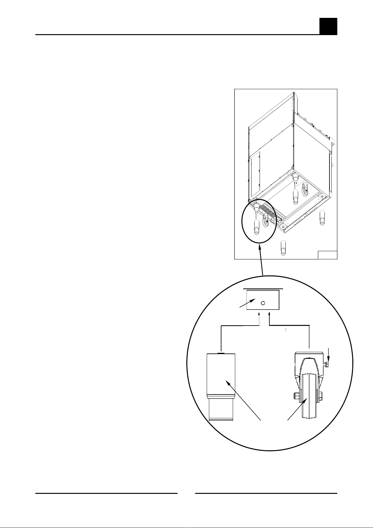
Fitting of Adjustable Feet / Rear Rollers to the Pasta Cooker
This appliance rear leg mount housings can be fitted with:-
Adjustable feet to assist with levelling of the appliance on uneven floors.
Rear rollers to enable the appliance to be easily moved for positioning and cleaning purposes.
Rear Adjustable Legs, fitting:-
1. Raise the appliance from the floor by approximately 75mm using
suitable lifting equipment (i.e. Palletiser / Forklift) to allow the rear
rollers to be removed.
2. Unscrew and remove the securing bolt that secures the rear roller
to the rear leg housing.
3. The rear rollers will drop freely from the rear leg housings.
4. Screw the rear adjustable feet into the rear leg housings and
tighten hand tight.
5. Lower the appliance back to the floor and adjust the adjustable feet
to level the appliance.
Rear Rollers, fitting:-
1. Raise the appliance from the floor by approximately 75mm using
suitable lifting equipment (i.e. Palletiser / Forklift) to allow the rear
adjustable feet to be removed.
2. Unscrew and remove both the rear adjustable feet from the rear
leg housings.
3. Fit the rear roller to the rear leg housing and align the screw hole in
the side of the rear leg housing with the threaded hole in the rear
roller.
4. Locate the rear roller to the leg support with the bolt supplied and
tighten the bolt using a 10mm A/F spanner.
5. Fit the second roller and tighten.
6. Lower the appliance back to the floor and adjust the front
adjustable feet to level the appliance.
Adjustable
Foot
Rear
Roller
Roller Securing
Bolt
Rear Leg
Housing
Fig 2.1

2
Installation
8
Blue Seal Evolution Series - G47 Gas Pasta Cooker © Copyright Moffat Ltd, March 2016
Amendment 6
Gas Connection
NOTE: ALL GAS FITTING MUST ONLY BE CARRIED OUT BY A QUALIFIED SERVICE PERSON.
1. Blue Seal Pasta Cookers do not require an electrical connection, they function totally on the gas supply only.
2. It is essential that the gas supply is correct for the appliance to be installed and that adequate supply pressure and volume are
available. The following checks should therefore be made before installation:-
a. The Gas Type the appliance has been supplied for is shown on coloured
stickers located above the gas entry point and next to the rating plate. Check
that this is correct for the gas supply the appliance is being installed for. The
gas conversion procedure is detailed in this manual.
b. Supply Pressure required for this appliance is shown in the ‘Specifications’
section of this manual. Check the gas supply to ensure that adequate supply
pressure exists.
c. Input Rate of this appliance is also stated on the Rating Plate fitted to the
inside of the access door and in the ‘Specifications’ section of this manual. The
input rate should be checked against the available gas supply line capacity.
Particular note should be taken if the appliance is being added to an
existing installation.
NOTE: It is important that adequately sized piping runs directly to the
connection joint on the appliance, with as few tees and elbows as
possible to give maximum supply volume.
3. A suitable joining compound which resists the breakdown action of LPG must be used
on every gas line connection, unless compression fittings are used.
The connection to the appliance is 3/4” BSP male.
NOTE: A Manual Isolation Valve must be fitted to the individual appliance supply line.
4. Correctly locate the appliance into its final operating position and using a spirit level, adjust the legs so that the unit is level and
at the correct height.
5. Connect the gas supply to the appliance.
6. Check gas operating pressure to as shown in the “Specifications” section. If the pressure is incorrect, adjust the pressure by
adjusting the regulator screw of the gas control valve as shown in the ‘Gas Conversion and Specifications’ section.
7. Check all gas connections for leakages using soapy water or other gas detecting equipment.
NOTE: Measure operating pressure at Burner Operating Pressure
test point on gas control valve, this is to be carried out with
burner operating at 'High Flame' setting. Operating pressure
is ex-factory set, through the appliance regulator and is not
to be adjusted, apart from when carrying out gas
conversion, if required. Refer to ‘Gas Conversion and
Specification’ Section for further details.
8. Turn ‘OFF’ the mains gas supply and bleed the gas out of the
appliance gas lines.
9. Turn ‘ON’ the gas supply and the appliance.
10. Verify the operating pressure remains correct
11. Check the pilot flame size. (Re-adjust if required by changing the
pilot injector. Refer to the Gas Conversion Section).
Rating Plate
Location
Fig 2.2
DONOT USE ANAKED FLAME TO CHECK FOR GAS LEAKAGES.
Warning
Gas Control
Valve
Burner Operating
Pressure Test Point
Fig 2.3

2
Installation
9
Blue Seal Evolution Series - G47 Gas Pasta Cooker © Copyright Moffat Ltd, March 2016
Amendment 6
Water Connection
NOTE: The water connection shall be installed in accordance with local water regulations in force and the applicable
standard/code, e.g. EN 1717 in UK / Ireland, PCA in Australia.
A cold water supply must be connected to the water inlet connection (R1/2" BSP), located 50mm from the LH side, 555mm from rear
and 135mm from the floor.
The water inlet pressure must be as follows:-
Minimum water supply pressure 150 kPa (22 psi).
Maximum water supply pressure 550 kPa (80 psi).
Drainage Connection
The water is drained from the appliance by means of a valve located behind the front control panel.
A waste water tundish must be fitted below the appliance drain outlet. This should be a minimum of 127mm (5”) major
diameter.
If required the drain outlet can be extended in order to exit above the tundish. All drain piping must be with materials
suitable for conveying boiling water.
Drain connection is R1" BSP drain / overflow.
Commissioning
The following commissioning checks must be carried out before the pasta cooker is handed over for use, to ensure
that the unit operates correctly and the operator(s) understand the correct operating procedure.
1. Before leaving the new installation;
a. Check the following functions in accordance with the operating instructions.
Light the Pilot Burner.
Light the Main Burner.
b. Ensure that each operator has been instructed in the areas of correct lighting, operation, and shutdown procedures for
the appliance.
NOTE: If it is not possible to get the appliance to operate correctly, shut off the gas supply and contact the supplier
of this unit.

3
Operation
10
Blue Seal Evolution Series - G47 Gas Pasta Cooker © Copyright Moffat Ltd, March 2016
Amendment 6
Burner Control
OFF Position
PILOT Burner
HIGH Flame
LOW Flame
Gas Control Knob
Piezo Igniter
(Behind Access Door)
Water Control Valve
3.1 Description of Controls
NOTE: A full user’s operation manual is supplied with the appliance and can be used for further referencing of installation,
operation and service.

3
Operation
11
Blue Seal Evolution Series - G47 Gas Pasta Cooker © Copyright Moffat Ltd, March 2016
Amendment 6
3.2 Explanation of Control System
Safety System
The purpose of the safety system is to shut off the flow of gas if
the pilot flame goes out. It is comprised of the flame itself, the
thermocouple, and the flame failure gas valve.
The pilot flame is lit by holding in the gas control knob, which in
turn temporarily pushes the plunger inside the safety valve
open and allows gas to flow through.
Once the burner is lit, the thermocouple will begin to generate
millivolts (after about 10 to 30 seconds of being heated) and
will energize the electromagnet inside the gas valve.
Once energized the electromagnet holds the plunger inside the
gas valve in the open position. The plunger has to have been
pushed all the way in for the electromagnet to be able to hold it
in place.
If the burner flame goes out, the thermocouple will cool after
about 10 to 30 seconds and stop generating millivolts. The
electromagnet will then de-energize, and the plunger will snap
shut, cutting off the flow of gas.
Detail of each component in the safety system is explained
below.
Sometimes a problem with the flame not staying lit after
releasing the button can be attributed to not pushing the
plunger all the way in.
This millivolt circuit is interrupted by a safety cut-out
thermostat. If the cut-out trips it cuts the millivolt supply to the
pilot valve magnet, shutting off the burners. The pasta cooker
is then inoperable until the cut-out has cooled below 100°C.
The purpose of this is to shut off the burners should the tank
run dry.
The Troubleshooting Guide (Section 5) should be used to
identify any incorrect operation. On correct identification of the
operating fault the Troubleshooting Guide will make reference
to the corrective action required, or refer to the Fault Diagnosis
section and / or Service section to assist in correction of the
fault.
The tip of the thermocouple is located in the pilot burner flame,
and the nut at the other end of the thermocouple screws into
the back of the gas valve.
Inside the copper tubing is a wire which is joined at the tip but
insulated from the rest of the tubing.
These two parts (the copper tubing and wire) make up the
‘Wiring’ for an electrical circuit. When these two dissimilar
metals, wire and tip, are heated an electrical voltage is
produced.
This type of thermocouple generates between 7 and 30
millivolts when heated in the pilot flame.
There are two reasons for this; gas has to flow through the
safety valve to make it possible to light the pilot burner,
secondly the plunger has to be pushed all the way in for the
electromagnet to hold it in. i.e. the electromagnet is strong
enough to hold the plunger in once there, but is not strong
enough to pull it in by itself.
Figure 3.2a
Figure 3.2b
Thermocouple
Gas flow
Electromagnet
Plunger
Shaft
Knob
Gas flow Plunger
Insulator Nut Conductor Tip
Internal
Wire
Thermocouple
The thermocouple is a device that generates electricity when
heat is applied to the tip.
Electromagnetic Flame Failure Gas Valve
The purpose of the safety valve is to shut off the flow of gas if
the pilot flame goes out.
Inside the body of the gas valve is an electromagnet connected
to a spring loaded plunger. When the electromagnet is
energized, it holds the plunger in, allowing gas to flow through
the valve. When the electromagnet is de-energized, the
plunger snaps to the closed position, stopping the flow of gas.
Millivolts are provided to the electromagnet by the
thermocouple (not shown) which generates millivolts when
heated. The thermocouple screws into a fitting at the back of
the gas valve to make an electric connection. By pressing in
the gas control knob, the plunger can be temporarily held open
while lighting.
Control Knob
4
Maintenance
12
Blue Seal Evolution Series - G47 Gas Pasta Cooker © Copyright Moffat Ltd, March 2016
Amendment 6
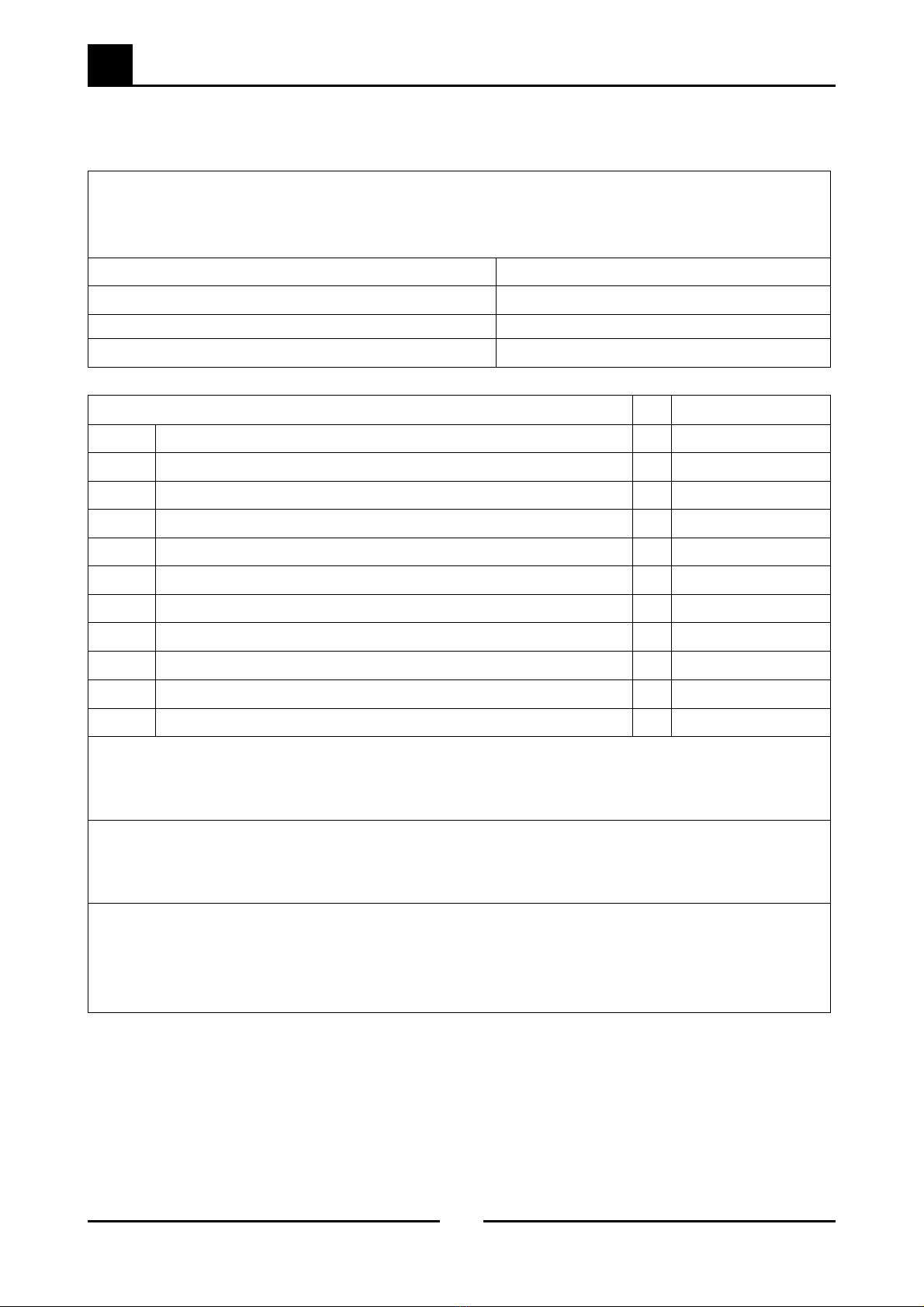
BLUE SEAL PASTA COOKERS - MAINTENANCE SCHEDULE
Business Name and Address:
Date: Service Report No.
Phone:
Serial No:
Clients Order No. Serviceman:
Model: Blue Seal G47 Remarks
1 Inspect exterior condition of unit.
2 Check working gas pressure, correct to rating plate. Pressure kPa
3 Check for gas leaks.
4 Check pilot flame, adjust as required.
5 Check burner operation.
6 Inspect thermocouple.
7a Check millivolt of thermocouple to safety cut-out. mV
7b Check millivolt of thermocouple to valve. mV
8Inspect is clean and free from blockages.
9 Check piezo ignition of pilot.
10 Check flue for build up of foreign objects.
Service Comments:
Additional work/repairs required:
Customers approval:
Name (print): Title:
Customers signature: Date:
Fax:
Suggestion: Photocopy this form and keep on file for continued use.

5
Fault Finding
13
Blue Seal Evolution Series - G47 Gas Pasta Cooker © Copyright Moffat Ltd, March 2016
Amendment 6
Fault Possible Cause Remedy
Piezo ignitor not sparking. Short in high tension lead.
(Refer Fault Diagnosis 5.2.2).
Piezo ignitor faulty.
(Refer Fault Diagnosis 5.2.2).
Replace lead.
(Refer Service Section 6.2.10).
Replace ignitor piezo.
(Refer Service Section 6.2.9).
Pilot won’t light. No gas supply.
Gas pressure too low.
Knob on gas control won’t go fully in.
Blocked pilot injector.
Ensure gas is connected and on and bottles
not empty.
Check gas supply pressure.
(Refer Specifications Section).
Remove obstruction. Correct control /
wrapper mounting.
Replace gas control valve.
(Refer Service Section 6.2.7).
Clean or replace pilot injector.
(Refer Service Section 6.2.9).
Pilot goes out when knob released. Releasing knob before the thermocouple
heated.
Pilot flame too small.
(Refer Fault: Pilot Flame Small).
Thermocouple faulty.
(Refer Fault Diagnosis 5.2.1).
Safety cut-out thermostat faulty.
(Refer Fault Diagnosis 5.2.1).
Gas control valve faulty.
Hold control in for longer (10 s), see if pilot
will stay lit.
Correct fault.
Replace thermocouple.
(Refer Service Section 6.2.1).
Replace safety cut-out thermostat.
(Refer Service Section 6.2.4).
Replace gas control valve.
(Refer Service Sections 6.2.7).
Pilot flame small. Gas pressure too low.
Pilot injector restricted.
Check gas supply pressure.
(Refer Specifications Section).
Clean pilot injector.
(Refer Service Section 6.2.2).
Pilot goes out when main burner comes on. Incorrect gas pressure.
Faulty gas control.
Check supply / adjust pressure.
(Refer Specifications Section).
Replace gas control valve.
(Refer Service Section 6.2.7).
Pilot goes out while in use. Gas supply - incorrect or fluctuating
pressure.
Draught at installation site(blowing pilot
out).
Thermocouple faulty.
(Refer Fault Diagnosis 5.2.1).
Safety cut-out thermostat faulty.
(Refer Fault Diagnosis 5.2.1).
Main gas control valve faulty.
Check supply / adjust pressure.
Shield pasta cooker from excessive breeze
Replace thermocouple.
(Refer Service Section 6.2.1).
Replace safety cut-out thermostat.
(Refer Service Section 6.2.4).
Replace gas control magnet.
5.1 Fault Finding Chart
ALL INSTALLATION AND SERVICE REPAIR WORK MUST ONLY BE CARRIED OUT BY QUALIFIED PERSONS.
Warning

5
Fault Finding
14
Blue Seal Evolution Series - G47 Gas Pasta Cooker © Copyright Moffat Ltd, March 2016
Amendment 6
Fault Possible Cause Remedy
Main burner will not light. Incorrect supply pressure.
Wrong size or blocked main burner
injector.
Small pilot flame.
(Refer fault: Small Pilot Flame).
Faulty gas control.
(Refer Fault Diagnosis 5.2.3)
Check supply correct pressure.
Replace / clean main burner injector.
(Refer Service Section 6.2.5).
Correct fault.
Replace gas control valve.
(Refer Service Section 6.2.7).
Pilot flame yellow / lazy. Gas pressure incorrect.
Restriction in pilot injector or aeration.
Check gas supply pressure.
(Refer Specifications Section).
Clean or replace injector as required.
(Refer Service Section 6.2.2).
Burner does not burn correctly (roar / light
back / incorrect colour).
Incorrect supply pressure.
Incorrect main injector size.
Burner faulty.
Check supply pressure.
Check main injector size and replace if
required.
(Refer Service Section 6.2.5).
Replace burner.
(Refer Service Section 6.2.6).
5
Fault Finding
15
Blue Seal Evolution Series - G47 Gas Pasta Cooker © Copyright Moffat Ltd, March 2016
Amendment 6
5.2 Fault Diagnosis
5.2.1 Pilot Drops Out
Pilot flame too small
If the pilot can be lit but the flame is too small to impinge on
the thermocouple, then check the gas pressure. If ok, then
remove the pilot injector from the pilot burner and check for
blockages and / or correct size.
Figure 5.2.1a
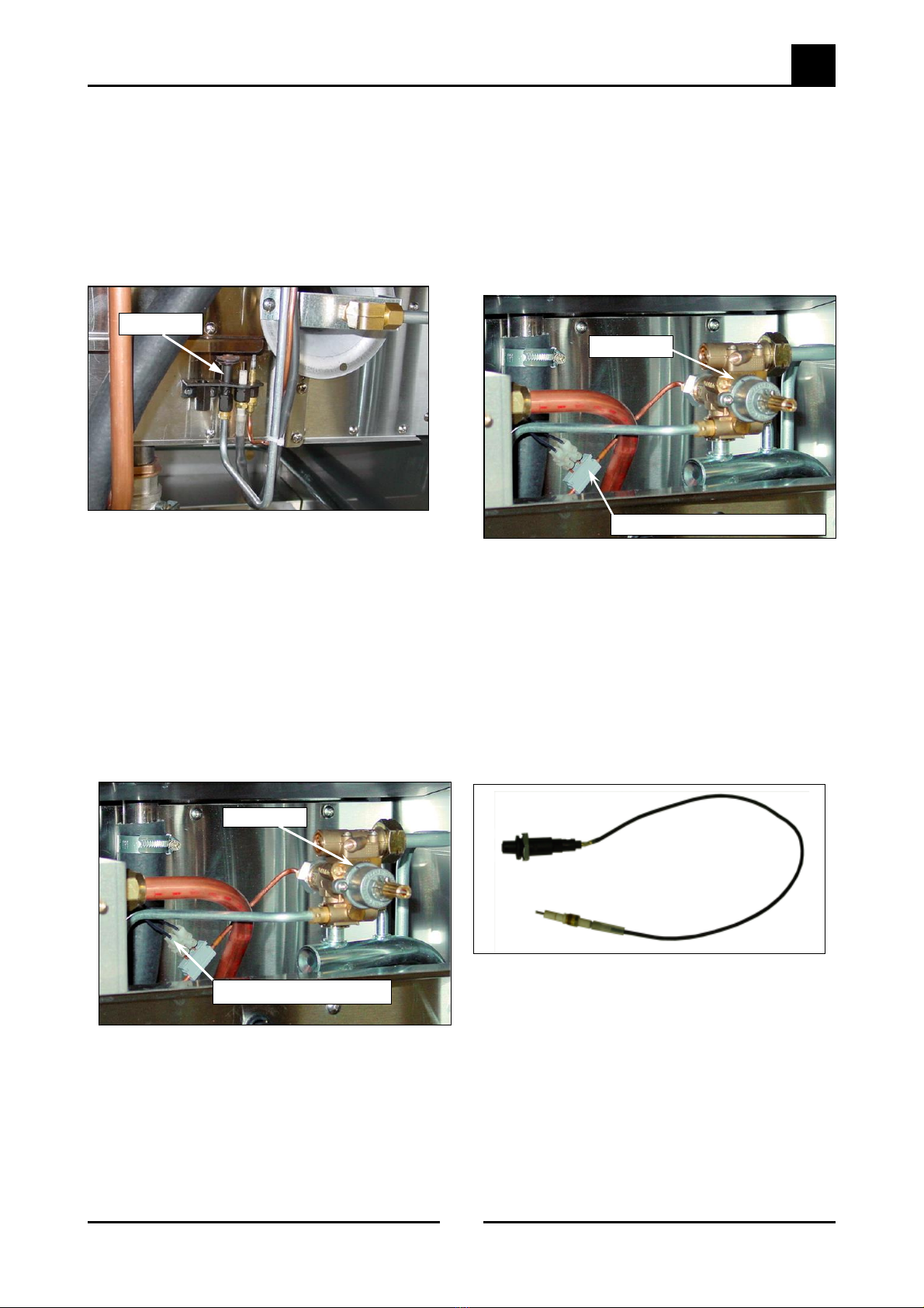
Thermocouple faulty
Check the thermocouple connection is firm and the safety
cut-out lead connection to the interrupter block on the
thermocouple is secure. (Loose connections will cause
resistance in the millivolt circuit and result in pilot outage.
If all connections are satis, light the pilot and whilst holding the
control knob in, measure the voltage from the pilot side of the
connecter block to earth (e.g. the body of the control valve).
This should read approximately 30mV.
If this reading is less than 20mV and there is good impingement
of the pilot flame onto the thermocouple, the thermocouple is
faulty - replace the thermocouple.
Figure 5.2.1b
Pilot side of Interrupter Block
Control Valve
Pilot Burner
Figure 5.2.1c
5.2.2 Piezo Ignitor Not Sparking
Short in high tension lead
If repeated sparking of the piezo shows only intermittent
sparking at the electrode, then the lead should be traced to find
the area of short. This can be visually seen as the spark arks.
If the lead is shorting the best solution is to replace it, as the
electrical insulation of the lead may have deteriorated.
If the spark arc can be seen at the electrode insulator at the
pilot burner instead of at the electrode tip, then the insulator
probably has a fracture and should be replaced.
Safety cut-out faulty
To check if the safety cut-out is faulty hold in the gas control
button and light the pilot (leaving the control button depressed
to keep the pilot alight). With a multimeter measure the voltage
from the gas control side of the thermocouple interrupter block
to earth. If the voltage is under 5mV (and the thermocouple is
generating at least 20mV) then the safety cut-out is faulty -
replace the safety cutout.
If all of the above checks out ok then check gas control or
thermocouple.
Gas Control side of Interrupter Block
Control Valve
Figure 5.2.2
Piezo ignitor faulty
If no spark at all can be generated, remove piezo ignitor and
hold close to cabinet body. Depress the piezo ignitor and if a
spark cannot be generated to the cabinet body the piezo ignitor
is faulty and should be replaced.
Note: If piezo ignition fails, the pilot can be manually lit
using a standard taper torch, lighter or matches,
until the piezo circuit is repaired.
Safety cut-out tripped
The safety cut-out is set at 115°C. If there is water in the tank
and the safety cut-out has tripped (open circuit) then the safety
cut-out is faulty.

6
Service Procedures
16
Blue Seal Evolution Series - G47 Gas Pasta Cooker © Copyright Moffat Ltd, March 2016
Amendment 6
ALL INSTALLATION AND SERVICE REPAIR WORK MUST BE CARRIED OUT BY QUALIFIED PERSONS
ONLY.
ENSURE GAS SUPPLY IS SWITCHED OFF BEFORE SERVICING
ALWAYS CHECK / TEST FOR GAS LEAKS AFTER SERVICE REPAIRS ON THE GAS SYSTEM
WARNING:
Section Page No.
6.1 Access......................................................................................................................................17
6.1.1 Control Panel........................................................................................................................................ 17
6.2 Replacement ...........................................................................................................................17
6.2.1 Thermocouple ..................................................................................................................................... 17
6.2.2 Pilot Injector ........................................................................................................................................ 18
6.2.3 Pilot Burner .......................................................................................................................................... 18
6.2.4 Safety Cut-out Thermostat ................................................................................................................... 18
6.2.5 Main Burner Injector............................................................................................................................. 18
6.2.6 Main Burner ......................................................................................................................................... 19
6.2.7 Gas Control Valve ................................................................................................................................ 19
6.2.8 Piezo Ignition Electrode ........................................................................................................................ 20
6.2.9 Piezo Ignitor......................................................................................................................................... 20
6.2.10 High Tension Lead ................................................................................................................................ 20
6.3 Adjustment / Calibration........................................................................................................ 20
6.3.1 Gas Control Valve Re-greasing............................................................................................................... 20
6.3.2 Low Fire Adjustment ............................................................................................................................. 20
6
Service Procedures
17
Blue Seal Evolution Series - G47 Gas Pasta Cooker © Copyright Moffat Ltd, March 2016
Amendment 6
Figure 6.1.1b
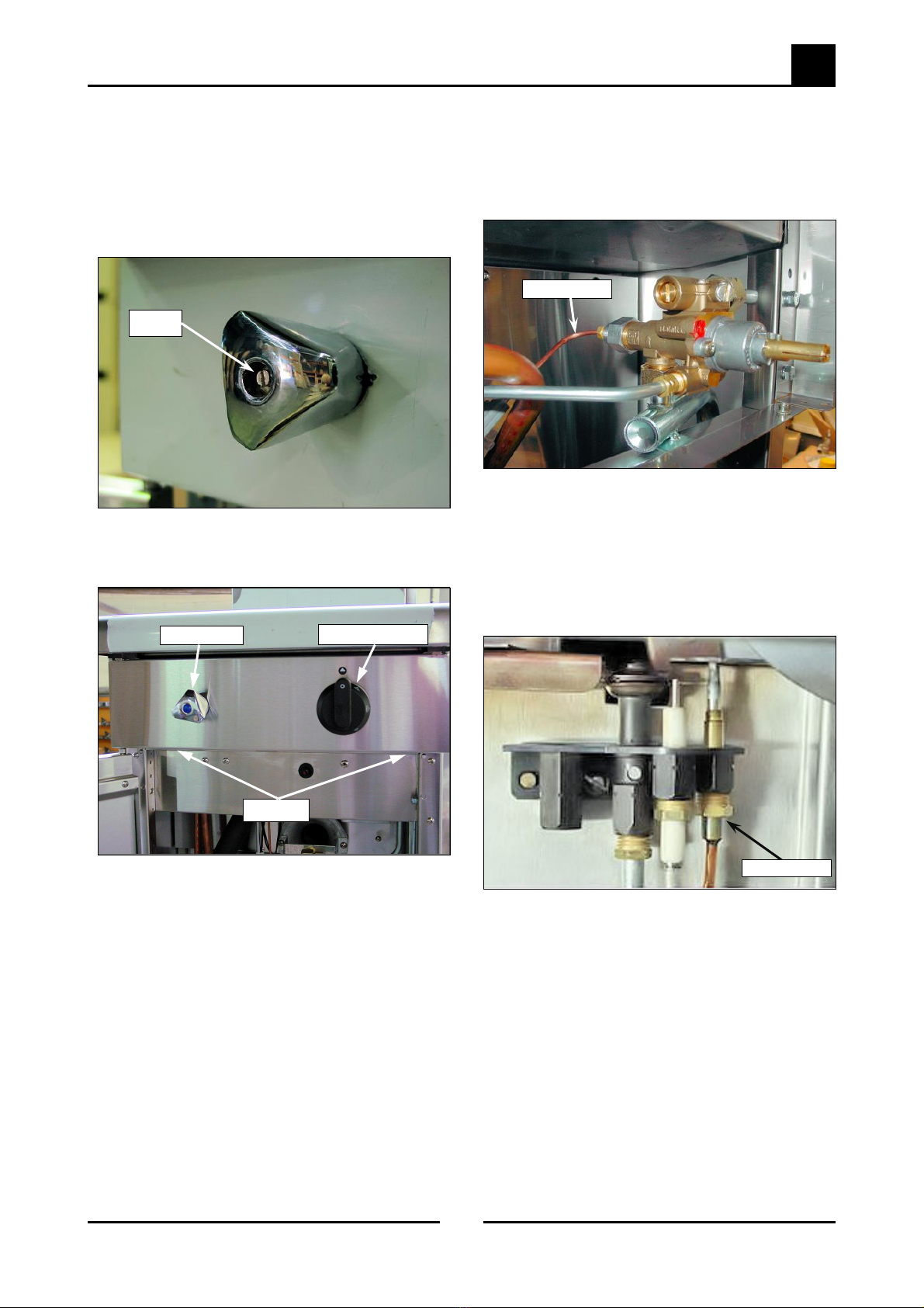
6.1.1 Control Panel
6.1 Access
1. Remove gas control knob by pulling knob from valve.
2. Remove water valve knob by levering out plastic cap in
centre of knob and undoing centre screw.
Figure 6.2.1a
6.2 Replacement
6.2.1 Thermocouple
Figure 6.2.1b
1. Disconnect thermocouple from gas control.
2. Unscrew the safety cut-out thermostat wires from the
connector block on the thermocouple.
3. Unscrew thermocouple securing nut from pilot burner.
NOTE: It may be necessary to remove the piezo
ignition electrode from the pilot assembly before
removing thermocouple.
4. Replace thermocouple and reconnect.
5. When screwing thermocouple back into gas control,
once thread has tightened up tighten another ¼ turn
only. Do not over tighten.
Thermocouple
Figure 6.1.1a
3. Remove 2 screws from underside of control panel and lift
panel off.
1 Screw
2 Screws
Water Valve Gas Control Valve
Thermocouple
6
Service Procedures
18
Blue Seal Evolution Series - G47 Gas Pasta Cooker © Copyright Moffat Ltd, March 2016
Amendment 6
Figure 6.2.3
Figure 6.2.4
Figure 6.2.5
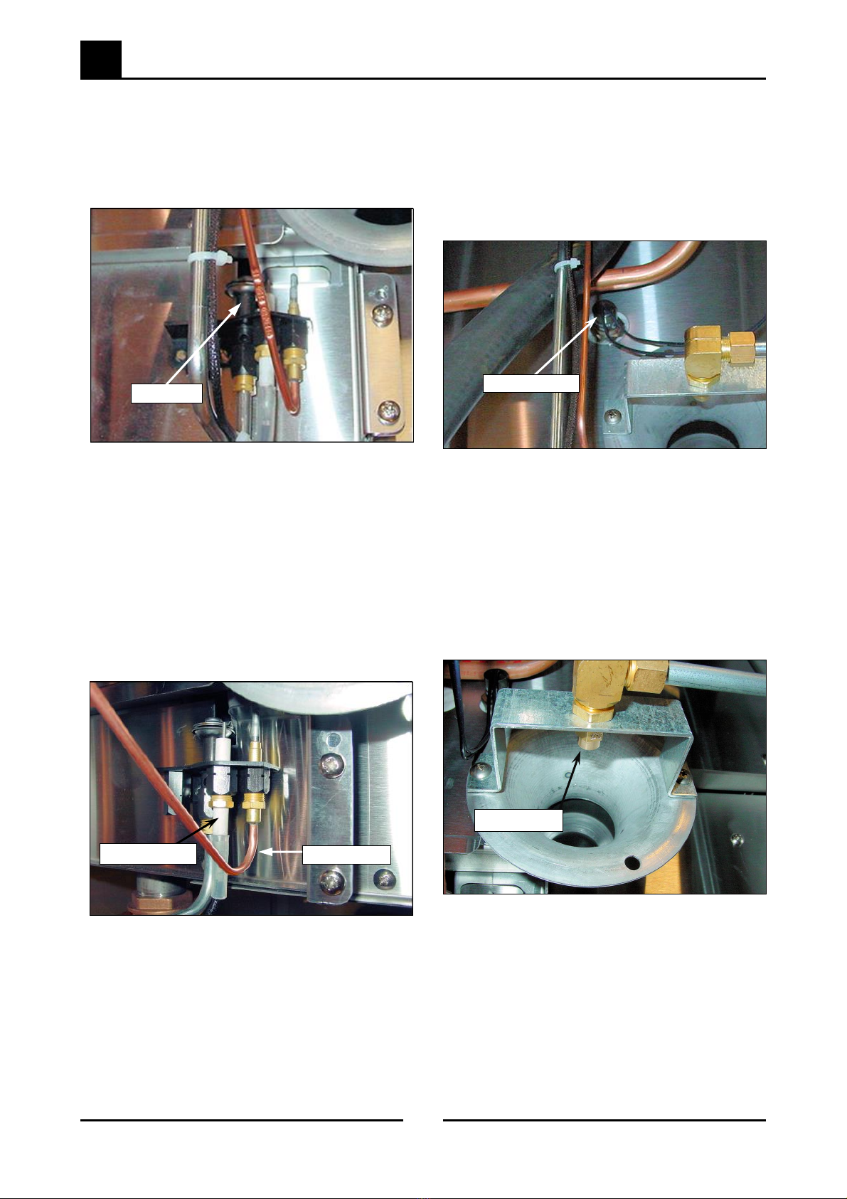
6.2.4 Safety Cut-Out Thermostat
6.2.3 Pilot Burner
6.2.2 Pilot Injector
1. Remove ignition electrode.
2. Disconnect pilot supply tube from pilot burner by
unscrewing nuts and olive.
3. Remove pilot injector, and clean or replace as necessary.
1. Disconnect the thermocouple and / or the piezo electrode
from the pilot burner.
2. Disconnect pilot supply tube from pilot burner by
unscrewing nut and olive.
3. Remove screw securing the pilot burner to front of the
pasta cooker, and remove pilot burner assembly.
NOTE: Ensure correct size injector is used (refer
Specifications section).
4. Re-assemble in reverse order.
1. Drain water from pasta cooker.
2. Remove control panel (refer 6.2.1 )
3. Disconnect safety cut-out leads from interrupter on the
thermocouple.
4. Using
7/8” tube spanner, remove the safety cut-out
thermostat from fryer tank.
1. Unscrew injector out of injector mounts.
2. Remove injector, and clean or replace as necessary.
Ensure correct size of injectors are refitted (refer
Specifications Section).
4. Replace pilot burner and re-assemble. Ensure correct
pilot injector is re-fitted (refer to the Specifications
Section).
5. Replace and re-assemble in reverse order, using sealant
suitable for 115°C on threads (Loctite 567
recommended).
6.2.5 Main Injector
Figure 6.2.6
Main Injector
Pilot Burner
Thermocouple
Piezo Electrode
Safety Cut-Out
Table of contents


