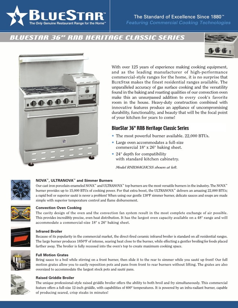
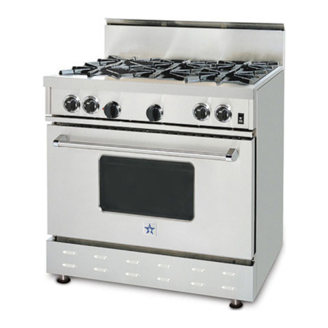
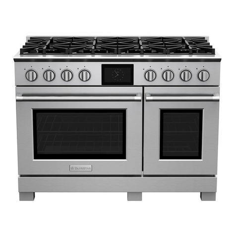
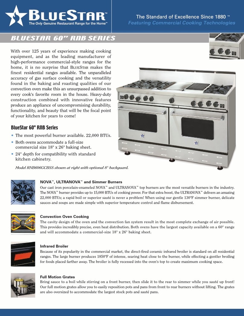
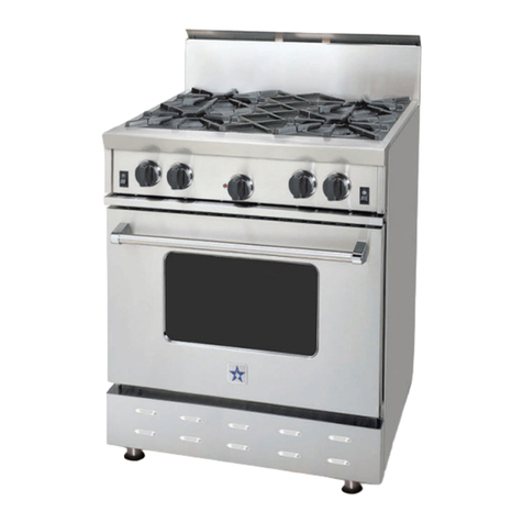
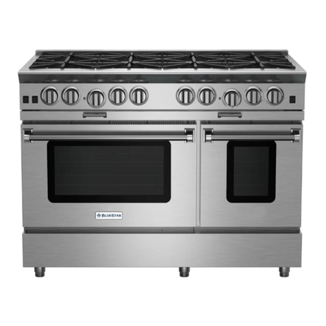
Blue Star RNB 30 Troubleshooting guide

- 1 -
INSTRUCTIONS
FOR THE SERVICE OF
GAS RANGES & COOKTOPS
FOR THE HOME
MODELS: RNB-30 RPB-30, RGTNB-30, RNB-36,RPB-36, RGTNB-36,
RNB-48, RGTNB-48, RNB 60, RGTNB-60, RCS-30, and RCS-36
Service Manual
Free-Standing Gas Range
600 Arlington Street, Reading, PA 19611
United States of America
2002

- 2 -
Since 1880, we have been dedicated to Quality! Our belief is that our success can
only be measured by the continuing success of our customers. We achieve
customer satisfaction by ensuring that each of our employees understands,
meets, and exceeds our customer’s expectations.
You as an authorized service agency are considered an employee to us. So
with that in mind you also need to understand, meet, and exceed “our”
customer’s expectations, before, during, and after the service requirements that
are performed on this quality product.
Our parts and service department has gone through great detail to supply this
service manual to all of the authorized service agencies. This manual along
with the current publicized part manual, will enable you to professionally,
quickly, and effectively repair their range if ever in need of service. Remember,
our customer loyalty is measured by it.
To order the “original” factory service parts, you can contact our authorized
parts agency at (610) 376-7826.

- 3 -
TABLE OF CONTENTS
Range & Cooktop Identification ............................4
Warranty Serial Plate Identification & Location..4
Product Warranty ....................................................5
Installation.................................................................6
Proximity to Side Cabinets Installation ................7
Rangetop Cutout and Specifications.....................8
Unpacking.................................................................9
High Shelf/Standard Backguard/Island Trim..10
Positioning ..............................................................11
Leveling ...................................................................11
Gas Connections.....................................................11
BTU Requirements.................................................12
Gas Conversion ......................................................13
Electrical Connection.............................................13
Installers & End-users Initial Check Info............13
Product Troubleshooting Monitor Checklist .....14
Oven Temperature Calibration............................15
Accessibility to service Parts ................................16
Disassembly Procedure of Product .....................17
Control Panel Removal .........................................18
Testing Procedure for Bake & Broil Igniters ......19
Oven Igniter Removal ...........................................20
Broiler Igniter Removal.........................................21
Testing Procedure for the Dual Gas Valve.........22
Oven Burner Air Shutter Adjustment.................23
Bake / Broil Thermostat Replacement................24
Convection Fan Removal......................................25
Oven Gasket Removal...........................................26
Door Panel Removal..............................................27
Complete Door Removal .....................................27
Indicator Light Removal .......................................28
Oven Light Switch Removal.................................29
I/R Broiler Spud (Orifice) Change ......................30
Top Burner Removal .............................................31
Open Top & CB Burner Air Shutter Adj.............32
Griddle Burner Removal.......................................33
Griddle Igniter Removal .......................................33
Griddle Thermostat Removal...............................33
Troubleshooting Guide .........................................34
Wire Diagrams:
RPB
30” 4-burner .............................................37
36” 4-burner w/griddle .........................38
36” 6-Burner.............................................39
36” 4-burner w/charbroiler. Unavailable
48” 8-burner .............................................40
48” 6-burner w/griddle .........................41
48” 6-burner w/charbroiler...................42
48” combination ......................................43
60”............................................ Unavailable
RGTPB
30”............................................ Unavailable
36”............................................ Unavailable
48”............................................ Unavailable
60”............................................ Unavailable
RCS
30”............................................ Unavailable
36”............................................ Unavailable
Manufacturers Checklist (Sample) ..................45
CAUTION!
DISCONNECT MAIN POWER SOURCE BEFORE
PERFORMING ANY MAINTENANCE ON THIS PRODUCT!!
Gas connections should be performed by a LICENCED
PLUMBER or LICENCED GAS FITTER in the Commonwealth
of Massachusetts!

- 4 -
RANGE AND COOKTOP IDENTIFICATION
(RANGE) (COOKTOP)
EXAMPLE:
RPB48-4GCB NAT-SS
EXAMPLE:
RGTPB48-4GCB NAT-SS
R= RESIDENTIAL R= RESIDENTIAL
P= POWER (Burner) G= GAS
B= BURNER T= TOP SECTION
48= 48” WIDE** P= POWER (Burner)
4= 4 OPEN TOP BURNERS B= BURNER
G= GRIDDLE (Optional) 48= 48” WIDE**
CB= CHAR-BROILER (Optional) 4= 4 OPEN TOP BURNERS
NAT= NATURAL GAS (Optional L.P. gas is available) G=GRIDDLE (Optional)
SS= STAINLESS STEEL FINISH CB= CHARBROILER (Optional)
NAT= NATURAL GAS (Optional L.P gas is available)
SS= STAINLESS STEEL FINISH
**Additional widths of 30”, 36”, and 60” are available and will be identified by the width size in the Model number. Also any colored
ranges will have the S.S prefix dropped from the end and no finish will be identified in the Model number.
WARRANTY SERIAL PLATE IDENTIFICATION AND
LOCATION
IDENTIFICATION:
EXAMPLE: SERIAL # 0201050
02=Last two digits of year (2002) 01=Month # (January=1; February=2; etc.) 50=the unit number for that months production
LOCATION:
NOTE: All Warranty Serial Plates are located on the top left inner side of the burner box section. The Top Grate and Ring Grate
assemblies must be removed from the top section of the Product, in order to view the rating plate, which is positioned vertical on the
Range.
GENERAL DISCLAIMERS:
IMPORTANT WARRANTY INFORMATION: No Product is ever shipped from the Manufacturing facility without a rating plate
installed on it. Verification of the product and it’s serial # must be reviewed prior to servicing the product, to insure all warranty claims can
be processes. Please note, NO WARRANTY CLAIMS will be processed or paid without proper Identification of the product.
Receipt of purchase may be required, if serial # and date of service are conflicting with the warranty period of the product. (PLEASE
NOTE: No warranty service will be provided on product that has been purchased on an “AS IS” purchase.)

- 5 -
Limited Warranty
WHAT IS COVERED?
FULL ONE (1) YEAR WARRANTY
This warranty covers all functional components of your unit. All repair, labor and replacement parts for parts found to be defective due to materials or workmanship
which occurs during normal household use within one (1) years from the documented delivery date will be repaired or replaced at the discretion of the manufacturer,
free of charge, when the range is located in the continental United States and Canada. See below for limits of warranty. Please refer to your installation checklist to
activate your warranty. All repairs or replacement service must be performed by an authorized service technician.
WHAT IS NOT COVERED?
Limits of Warranty
This warranty shall apply to products manufactured on or after February 22, 2002 and located in the continental United States and Canada. Warranty labor shall be
performed by an authorized service agent. Unit must be accessible for service in the home as well as accessible via public highways. Your dealer or the
manufacturer assumes no responsibility for travel of over 100 miles round-trip. Additional costs shall be the responsibility of the consumer, including additional
mileage, non-standard service and special equipment to remove the unit for service so there is accessibility on all sides of the unit.
The warranty does not apply to damage resulting from abuse, natural disaster, “acts of God”, loss of electrical power to the product (for any reason), alteration for
outdoor use, improper installation, misuse during installation or improper operation, instruction on the use of the product, unauthorized adjustments and calibrations
performed on the product, nor damage due to harsh chemicals (i.e. cleaning products improperly applied). Cosmetic parts such as top grates, ring grates, plate rail,
kick panel, body sides, glass, control panel, door panel, back guards, oven seals, light bulbs, and enameled parts are warranted to be free from defect in material and
workmanship at the documented delivery date. All claims for these items must be reported immediately! Any claims not reported within seven (7) calendar days
will not be honored. The warrantor agrees to repair or replace, at its option, any part that fails or is found to be defective, during the warranty period. Items, including
but not limited to, those such as calibrations, replacements for parts improperly maintained (i.e. cleaning, etc), chipping of porcelain, normal adjustments after
setups, cleaning of parts, shipping damage, unauthorized service, discoloration of griddle, improper installation (such as no regulator), damage caused by accident or
abuse, and units installed in non-residential settings such as day cares, bed and breakfasts, hotels, nursing homes, churches, etc. are not covered under this warranty.
Warrantor is not responsible for consequential or incidental damage. Warranty does not apply to commercial usage, or to products with altered or removed serial
numbers. Owner shall be responsible for proper installation, providing normal care and maintenance and proof of purchase and delivery date upon request as well as
making the appliance accessible for service.
Warrantor’s liability on a claim of any kind, with respect to the goods or services herein, shall in no case exceed the price of the goods or services or part thereof
which gives rise to the claim. Also, parts and service needed to fulfill warranty obligations are to be performed at the manufacturers’ discretion. Normal coverage
does not include broken glass, rust, paint and porcelain finish, gasket materials, ceramic materials, light bulb or fuses.
SERVICE
WARRANTY SERVICE
Under the terms of this warranty, service must be performed by a factory-authorized service agent or representative. Service will be provided during normal
business hours. Labor performed at overtime, premium rates, equipment needed to repair or replace parts shall not be covered by this warranty. To obtain service,
call your dealer/distributed or the manufacturer at (610) 376-7826. Prior to calling, please have ready the model and serial number as well as the documented
delivery date. IMPORTANT! Retain original proof of purchase to establish warranty period.
WARRANTY IS NOT TRANSFERABLE
Any implied warranties of merchantability and fitness for particular purpose or any other warranty applicable to the equipment are limited in duration to the period
of coverage of this express written warranty. This warranty grants specific legal rights to the purchaser. Other rights, which may vary from state to state, may also
apply. Title to the merchandise passes to the consignee upon acceptance by the carrier. After acceptance by the carrier, the merchandise travels at the risk of the
purchaser. In the event of freight damage do not refuse shipment. Advise the agent of the damage on the freight bill before any freight charges are paid. Also, when
signing for freight, always label the freight bill “must inspect for concealed damage”. File a claim for damages with the freight agent. In the event of concealed
damage (shipment arrives in apparent good order, but upon unpacking is found to be damaged) immediately notify the freight agent in writing and retain a copy of
the notification.
DISTRIBUTORS
Signature Marketing GoldenWest Sales Grande Chef Gulf Central Corp Louis W. Howat & Sons, Inc.
103 Fairfield Road 3656 Enterprise Avenue 4591 Metropolitain East Blvd. 7819 Professional Place 6201 Humphreys Street
Fairfield, NJ 07004 Hayward, CA 94545 Anjou, Quebec H1J 3C1 Tampa, FL 33639 Harahan, LA 70123
(973) 575-7785 (510) 784-6835 (514) 374-5343 (800) 282-3892 (800) 535-2673
FAILURE TO EXECUTE YOUR INSTALLATION CHECKLIST AND RETURN THIS FORM EXECUTED WILL INVALIDATE YOUR WARRANTY
Attention Service Agents! Please obtain authorization to perform warranty service prior to performing any
work! This will ensure prompt payment of your service invoice. To obtain authorization, contact a distributor of this
product. Please note: the closest distributor may not always be the same as the distributor of record for this unit.
Therefore, you must have the dealer information available when calling the manufacturer or the closest distributor.

- 6 -
INSTALLATION
REQUIREMENTS
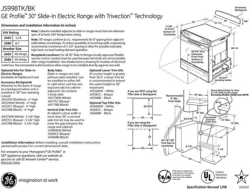
1. This unit has been designed to be installed directly against rear walls and side base cabinets. It cannot, however, be installed
directly against tall side cabinets, sidewalls, tall appliances, or base cabinets extending beyond 24”. (see, 'Proximity to Side
Cabinets').
2. The side trims must be at least 11/16" above adjoining counter top surfaces (see 'Proximity to Side Cabinets').
3. Any openings in the back wall or floor of the installation site must be sealed.
4. Electrical requirements: 120 volt, 15 amp, 60Hz properly grounded household current. The receptacle must be positioned to
prevent strain and physical damage to the power supply cord.
5. Gas requirements: Natural Gas...5.0" WC; LP Gas 10.0" WC.
6. Proper ventilation must be installed for this product. For best results, consult with your dealer or HVC installer for minimum
CFM’s.
7. The installation of this appliance must conform with local codes, or in the absence of local codes, with the National
Fuel Gas Code, ANSI Z223.1.
In Canada, installation must be in accordance with the current CAN/CGA B149.1 and .2 installation codes and/or local
codes.
NOTE:
Be sure to check the rating plate label located on the left side under the burner grate to confirm that the appliance is properly equipped for the
gas supply.
WARNING!
ELECTRICAL GROUNDING INSTRUCTIONS:
This unit must be electrically grounded in accordance with local codes, and the National Electrical Code ANSI/NFPA No.
70, (or latest edition). A licensed electrician must make installation. This appliance is equipped with a three-prong
grounding plug for your protection against shock hazard, and should be plugged directly into a properly grounded
receptacle.
Do not cut or remove the grounding prong from this plug.
In Canada, the installation must be in accordance with the current
CSA C22.1 Canadian Electrical Code, Part 1, and local codes.
**IMPROPER INSTALLATION WILL VOID WARRANTY**

- 7 -
PROXIMITY TO CABINETS
1. Base Cabinets: The unit may be installed directly adjacent to base cabinets at a maximum height of 36".
IMPORTANT: The unit's side trim pieces (both left and right) MUST be 11/16" above adjacent base cabinet counter top.
2. Tall Cabinets etc.: The unit CANNOT be installed directly adjacent to tall cabinets, tall appliances, sidewalls or other vertical
surfaces above 36" high. A 6" side clearance from the unit to such combustible surfaces must be maintained 18" above the
counter height.
3. Wall Cabinets: Wall cabinets to the side(s) of the shelf/flue riser must be a minimum of 18" above the counter.
Wall cabinets above the unit must be minimum of 36" above the unit top-cooking surface for the full width of the unit. The
maximum depth of wall cabinets must be minimum 13".
NOTE: The unit shown above is a graphic representation of a model to show acceptable clearances. Actual units will vary in
appearance.
Note!!
Oven door
cannot be
recessed into
the base
cabinetry or
damage to
surrounding
cabinetry
may occur!!!

- 8 -
RANGETOP CUTOUT AND SPECIFICATIONS
UnitSizeCutoutWidth
30”-30”
36”-36”
48”-48”
60”-60”
Depth – 24”
Height – 7 ¼”
Lower Support Ledge 1 ½” Maximum

- 9 -
UNPACKING
1. Check the packaging for any damage. If damage is visible on the packaging, you should mark the bill of lading for possible
concealed damage.
2. Check to make sure that the container is upright. If unit is not upright, major damage may occur. If damage is discovered, do not
refuse delivery, but contact the carrier and file the appropriate freight claims. Do not contact the factory, as responsibility for
shipping lies with the carrier, dealer, and end-user. We will assist with claims, but such assistance does not concede responsibility.
3. Cut the straps and lift the box directly upward and off the unit. Do not hammer on the carton.
4. Thoroughly check the unit for damage. If damage is discovered, do not refuse delivery, but contact the carrier and file the
appropriate freight claims. Do not contact the factory, as responsibility for shipping lies with the carrier, dealer, and end-user. We
will assist with claims, but such assistance does not concede responsibility.
5. Remove and unpack any accessories shipped with the unit, making sure that no hardware or accessories are left to be disposed of
accidentally.
6. After unpacking, remove manufacturers tape from legs. Raise the unit to remove the shipping pallet. In order to remove unit
from pallet, lift unit in an upward position from the BOTTOM of the unit while holding pallet in place. NOTE: The unit is
attached to the pallet for protection during shipment. It is also important to wear protective gloves to avoid contact with sharp
edges. Tilting the unit could prove dangerous or cause damage to the unit and/or floor. DO NOT LIFT RANGE BY THE
OVEN DOOR HANDLE!

- 10 -
HIGH-SHELF / STANDARD BACKGUARD / ISLAND TRIM
A standard backguard for the unit must be mounted before the unit is placed in its final position.
Installation instructions are located with your backguard, high-shelf and/or
island trim.
Note: If the island trim option is used without the 6” clearance
recommended, a non-combustible rear wall extending a minimum of 6”
below the countertop must be used. In no cases will we accept
responsibility for claims which may result from heat damage to a rear
wall or counter, including cosmetic damage. It is the responsibility of
the owner/end user to ensure that the material used in such applications
is not only non-combustible, but is also truly heat resistant.
Rear of Range
(6) Sheet Metal Screws

- 11 -
POSITIONING
POSITIONING
A rolling lift jack, air sled, or pallet jack should be used for positioning the unit. Do not push against the edges or sides of the unit in
an attempt to slide it into position. Although all metal parts are deburred during manufacture, serious injury could occur if the unit
were to move suddenly while being positioned by hand. We recommend you use gloves during installation process. Do not use the
oven door handle as a “pull.” Pushing or pulling the unit increases the possibility of damage to the legs and floor.
LEVELING
For optimum performance, (particularly in baking), the range must be leveled by the leveling bullet legs installed in the range by
screwing the bullet in or out.
A carpenter-type level should be placed on the oven rack, and the unit should be leveled side-to-side, front-to-back, and diagonally.
NOTE: Installing this range on a combustible surface without legs will void UL/cUL classification.
GAS CONNECTION
The gas supply line must be the same size or larger than the gas inlet on the unit. This unit has a ½” or ¾” NPT inlet accessed from the
back of the unit. We recommend the gas inlet should be approximately ¼ “ larger than the NPT inlet (see page 12 for more
information). Sealants used on all pipe joints must be resistant to LP gas. Any openings in the wall behind the unit, or the floor
beneath must be sealed.
1. An installer-provided manual shut-off valve must be installed in the gas service line ahead of the appliance. The shut-off valve must
be in a position where it can be accessed quickly in the event of an emergency.
2. All heavy-duty cooking equipment must have a pressure regulator on the incoming service line for safe and efficient operation.
Service pressure may fluctuate due to local demand. An external regulator is not required on the unit, as a regulator is built in to each
unit at the factory. Under no condition should the factory-installed regulator be by-passed.
This unit was constructed for use with either natural or propane (LP) gas. Verify that the unit and the incoming gas supply are
compatible by checking the rating plate label, located on the left side of the unit under the burner grate. The correct regulator, valves,
and orifices are installed at the factory for natural/LP gas. See the following section, titled "GAS CONVERSION," for detailed
conversion instructions, if required.
Incoming line pressure should be checked with a manometer. The correct operating manifold pressure for natural gas is 5.0" WC; for
Propane (LP) gas, 10.0" WC. Incoming line pressure upstream of the regulator should be 1" WC higher than the correct operating
manifold pressure. The regulator used on this unit will withstand a maximum input pressure of 1/2 psi, (12" WC). If the incoming line
pressure is higher than this maximum rating, a step-down regulator is required upstream of the unit's factory-installed regulator.
The appliance and its individual shut-off valve must be disconnected from the gas supply piping system during any pressure testing of
the homes’ gas line system at pressures in excess of 1/2 psig, (3.5kPa).
The appliance must be isolated from the gas supply piping system by closing its individual shut-off valve during any testing of the
homes’ gas system at pressures equal to or less than 1/2 psig, (3.5kPa).
3. Rigid connections: Incoming gas is brought from the inlet pipe at the rear of the unit to the pressure regulator, then through the
upper manifold for distribution. The only connection necessary is from the service line, through the installer-supplied shut-off valve, to
this inlet pipe.
Be sure to double check any installer-supplied pipes and fittings, and/or blow compressed air through them to clean out dirt particles,
threading chips, or other foreign matter before connecting the unit to the service line. Such particles will clog orifices when gas pressure
is applied. Service to clean such clogs is not covered by the warranty.
Check all gas connections for leaks using a soapy solution before lighting any pilots. DO NOT USE AN OPEN FLAME TO
CHECK FOR LEAKS! Using an open flame to check a new connection is not only dangerous, but it will also miss small leaks that a
soapy solution would detect.
4. Flexible connections: If the unit is to be installed with flexible couplings and/or a "quick-disconnect," the installer must use a
commercially approved AGA Design Certified flexible connector of at least 1/2" NPT, in compliance with ANSI Z21.41.
In Canada, a connector complying with CAN 16.10 - 88, and a quick disconnect device complying with CAN 16.19M - 79 must be
installed with a strain relief device to guard against the transmission of strain to the connector.
5. Air shutter adjustments are the responsibility of the installer, not service.

- 12 -
B.T.U. RATING REQUIREMENTS
These are the total approximate B.T.U. Ratings based on twelve inch cooking sections of unit. The gas line size must lie within compliance with
the state code 248CMR for the Commonwealth of Massachusetts.
Model Number Approximate BTU Line Size
RPB-30-IR 115,000 ½”
RPB-36-IR 125,000 ½”
RPB-48-IR 155,000 ½”
RPB-60-IR 215,000 ¾”
RPBGT-30 70,000 ½”
RPBGT-36 80,000 ½”
RPBGT-48 94,000 ½”
ALL RPB RANGES-COOKTOPS-INDOOR BBQ
DESCRIPTION NAT. ORIFICE SIZE L.P. ORIFICE SIZE LISTED BTU
P/H ACTUAL BTU P/H FIXED OR
ADJUSTABLE PRESSURE REG.NAT/LP
OPEN TOP BURNER LARGE # 48 P/N 709548 # 56 P/N 709956 18,000 15400/14,500 ADJ.
OPEN TOP BURNER SMALL # 51 P/N 709551 # 57 P/N 709957 14,500 15,400/14,500 ADJ.
SIMMER BURNER # 78 P/N 734678 # 87 P/N 734687 750 750/750 FIXED
GRIDDLE BURNER (U) # 51 P/N 709551 # 57 P/N 709957 15,000 15,400 /14,500 ADJ.
CHARBROILER BURNER (U) # 51 P/N 709551 # 57 P/N 709957 15,000 15,400/14,500 ADJ.
I.R. BROILER BURNER # 50 P/N 735550 # 56 P/N 735556 16,000 16,800/16,900 FIXED
OVEN BURNER-30/36" # 42 P/N 718701 ASY #52 P/N 718702 ASY 30,000 29,500/29,500 FIXED
OVEN BURNER-48" # 51 P/N 705401 # 57 P/N 705401 15,000 15,400/14,500 ADJ.
5"to 10" & 4" TO 10" REG.
P/N 718301 REQD. ON ALL
MODELS LISTED IN THIS
SECTION
INDOOR CHARBROILERS 15" AND 30" UNITS
DESCRIPTION NAT. ORIFICE SIZE L.P. ORIFICE SIZE LISTED BTU
P/H ACTUAL BTU P/H FIXED OR
ADJUSTABLE PRESSURE
REG.NAT/LP
CHARBROILER BURNER (U) # 51 P/N 709551 # 57 P/N 709557 20,000 15,400/14,500 ADJ.
REG. P/N 718301
REQD. ON ALL
MODELS LISTED IN
THIS SECTION
PRESTIGE SEALED-BURNER RANGES
DESCRIPTION NAT. ORIFICE SIZE L.P. ORIFICE SIZE LISTED BTU
P/H ACTUAL BTU P/H FIXED OR
ADJUSTABLE PRESSURE
REG.NAT/LP
LARGE BURNER #51 P/N 734651 # 57 P/N 734657 15,000 15400/14,500 FIXED
SMALL BURNER P/N 734657 #70 P/N 734670 6,000 6,350/6,000 FIXED
REG. P/N 718301
REQD. ON ALL
MODELS LISTED IN
THIS SECTION
OUTDOOR BBQ 27”, 36”, & 48” UNITS
DESCRIPTION NAT. ORIFICE SIZE L.P. ORIFICE SIZE LISTED BTU
P/H ACTUAL BTU P/H FIXED OR
ADJUSTABLE PRESSURE
REG.NAT/LP
H- BURNER #45 P/N 709545 #55 P/M 709555 20,000 20,500/21,200 FIXED
U- BURNER #45 P/N 709545 #55 P/M 709555 20,000 20,500/21,200 FIXED
ROTIS. IR BURNER- SM #54 P/N 709554 #65 P/M 709565 10,500 9,200/9,600 FIXED
ROTIS. IR BURNER- LG #51 P/N 709551 #59 P/M 709559 14,000 13,700/13,300 FIXED
OPEN TOP BURNER LARGE # 51 P/N 734651 # 57 P/N 734657 14,500 13,700/14,500 FIXED
SMOKER BURNER #63 P/N 707563 #72 P/N 709572 5,000 4,200/4,900 FIXED
REG. P/N 717301
4” NAT/10” LP
REQD. ON ALL
MODELS LISTED IN
THIS SECTION
Please Note!
The size of the LP supply tank should
be calculated by the total number of
BTU requirements of the gas
appliance.
The pressure supplied from the LP
supply tank should be between 11”
WCI and 13” WCI. The regulator on
your product will supply a steady 10”

- 13 -
WCI to the manifold. (WCI=Water
Column Inches)

- 14 -
GAS CONVERSION
WARNING
: IN ORDER TO AVOID A FIRE OR EXPLOSION, CAUSING PROPERTY DAMAGE, PERSONAL
INJURY OR DEATH; PRECAUTION MUST BE TAKEN WHEN PERFORMING A CONVERSION BY ENSURING
THAT THE VALUES IN THE GAS PRESSURE CHARTS ARE EMPLOYED WHERE APPLICABLE.
Any field gas conversions will automatically void the manufacturers warranty!! Gas conversions should only be performed by
a licensed plumber or licensed gas fitter in the Commonwealth of Massachusetts to assure a complete and
safe conversion. Please contact your distributor for additional information regarding gas conversion.
ELECTRICAL CONNECTION
There is no connection necessary beyond plugging the unit into a polarized, grounded, 120-volt, 60-Hz, 15-amp circuit. This circuit,
however, MUST be grounded and properly polarized.
The unit is equipped with a NEMA #5-15P power cord, accessed by removing the rear panel, and if an extension is required, it must be
at least this gauge.
NOTE: If electrical power is not supplied or is interrupted, the unit will not be operational.
WARNING ! ! !
This appliance is equipped with a three-pronged grounded plug for your protection against shock hazard and should be
plugged directly into a properly grounded receptacle.
Do not cut or remove the grounding prong from this plug.
If the unit is not grounded or its polarity is reversed, severe shock hazards can exist.
**Removing the third prong will void the manufacturers warranty**
INSTALLERS & END-USERS INITIAL CHECK
All units are adjusted and tested before leaving the factory. The manufacturer has supplied you with an installers point checklist in order for
your technician to properly install your new unit.
Requirements for your unit must be installed to factory specifications. Failure to perform the installation checklist and returning it will void
the warranty coverage agreement. When this range is properly installed and connected to proper gas and electrical service, it will operate
properly. Any issues regarding service should be directed to your distributor or the factory at (610) 376-7826.

- 15 -
PRODUCT TROUBLESHOOTING MONITOR CHECKLIST
(Must be performed prior to oven temperature calibration)
Below are a list of requirement’s needed to be monitored prior to trouble-shooting the product for miscellaneous
dysfunctions or reported poor performance.
1. Monitor house voltage before and during testing of product.
Must maintain voltage at minimum: 117 VAC.
From__________ To __________
2. Monitor Burner Igniters (glo-coils) for correct current during test.
Must maintain 3.4 amps or greater.
From__________ To __________
3. Monitor voltage across the thermal valve connectors during test.
Must be between 3.03 and 3.3 volts A.C
From__________ To __________
4. Check gas pressure at the manifold (remove a burner, install tube from a manometer onto the orifice without
burner on it). Ignite burners on top section during test to equalize pressure in the manifold.
• Check to make sure the inside diameter of the supply line is appropriate for the gas feed to the product
(See B.T.U Rating chart.)
• Natural W.C.P must be 5” actual is:__________
• Propane W.C.P must be 10” actual is:__________
Supply pressure from the meter or L.P tank must be at least 6” W.C.P. For natural gas and 11”
W.C.P for L.P gas. Pressure should never exceed 12” W.C.P or ½ p.s.i.
5. Be sure the thermostat bulb is straight and properly spaced from the oven liner in the bulb clips.
PLEASE NOTE
If all of the above readings check out correctly, and the oven temperature is not within the 25-
degree temperature swing, calibration of oven thermostat is required.

- 16 -
OVEN TEMPERATURE CALIBRATION
1. Be sure the thermostat bulb is straight and properly spaced from the oven liner. The sensor bulb clips should be in
place.
2. Place a weighted thermo-couple in the center of the oven cavity.
3. Set oven temperature control to 350 degrees Fahrenheit (convection oven, 325 degrees Fahrenheit).
4. Cycle oven five times. Average the third, fourth, and fifth cycles. The temperature is acceptable if the average is 350
degrees Fahrenheit (convection oven, 325 degrees Fahrenheit), plus or minus 25 degrees Fahrenheit.
Utilize the chart below to document data:
Temperature: Conventional Oven – 350 degrees
Cycle 1 2 3 4 5 Average
High XXXX XXXX
Low XXXX XXXX
Temperature: Convection Oven – 325 degrees
Cycle 1 2 3 4 5 Average
High XXXX XXXX
Low XXXX XXXX
If results are insufficient, the following procedure is required to calibrate bake thermostat.
1. Remove the knob of the oven thermostat.
2. Remove the white substance material located inside the stem of the thermostat. You will need a small straight-
tipped screwdriver.
3. With the small screwdriver, turn the center screw clockwise to increase the temperature and counter-clockwise to
decrease the temperature. Note! ¼ turn is equal to 25 degrees.
4. After calibration, cycle oven again four to five times and average the last two cycles for your final reading.

- 17 -
ACCESSIBILITY TO SERVICE PARTS
Front Accessible
Electrical 703303 Oven Burner Igniter
703303 Broiler Burner Igniter
702901 Oven Thermostat (Large Oven)
719501 Oven Thermostat (Small Oven)
729201 Re-ignition Spark Module
732901 Switch-Dual Simmer
733301/733302 Electrode Assemblies
705101 Thermostat Griddle
703303 Griddle Burner Igniter
703303 Char-broiler igniter
157101 Fan motor assembly
Gas 735501 Broiler Burner (Brant Radiant) 2000
705401 Single thermo-valve (Small Oven)
156901 Gas valve Dual Simmer Valve Assy.
718301 Pressure Regulator
Front Accessibility – indicates that the range does not need to be removed from the installed location, but will
require the removal of an exterior cabinetry part, valve panel, or kick plate. The removal of the top grate and
ring grate may also be required.
Rear Accessible
Electrical 703601 Light Assembly
718202 Power Cord (5 foot)
Gas 718901 Dual Thermo-valve 3/8
735550 Cone Orifice Nat #50 (after 500554)
735556 Cone Orifice L.P. #56 (after 500554)
Rear Accessibility – Indicates that the range needs to be removed from the installed location for any parts
replacement as listed above.

- 18 -
DISASSEMBLY PROCEDURE OF PRODUCT
Below is a brief summary of components and the required parts needed to be disassembled from the unit during replacement or repair.
Component Removal Parts
Oven Burner Igniters Oven Bottom
Kick Panels (for wire disconnect)
Broiler Burner Igniters None
Oven Thermostat Control Panel
Thermostat bulb shield
Top Grates
Ring Grates
Reignition Spark Module Control Panel RPB/RPBGT
Thermostat Griddle Griddle Plate (Pull wires forward)
Control Panel
Manifold Gas Valves (all) Control Panel
Valve Switches Control Panel
Pressure Regulator Top Grates
Ring Grates
Regulator Shield
Single Thermo-valve: small oven Oven Bottom
Kick Panel (for wire removal)
Single Thermo-valve: Griddle Control Panel
Single Thermo-valve Char-broiler Control Panel
Please note: This is a generic example of parts removal; all models will vary based on the options and configuration of unit.

- 19 -
CONTROL PANEL REMOVAL
The following procedure must be performed to properly remove the control panel.
1. Shut off power to the unit.
2. Remove the control panel, by first removing all the control knobs from the valve or thermostat stems. Continue to
remove the securing screws located in the upper flange located underneath the plate rail and the screws located
on the lower flange located above the pull out grease pan handles.
3. Disconnect the wires from the switch light and fan, carefully marking the location of the wires in order to rewire
the switches positioned in the new control panel, or to simply replace wires in the correct location.
4. With two fingers, put pressure on the tabs located on the back of the switch to enable it to be pressed forward and
out of the control panel. If replacing the control panel, remove all bezels to be reused.
5. Re-install switches into the control panel along with the bezels.
6. Rewire switches as per disconnected configuration.
7. Re-install control panel by reversing step 2.
8. Reconnect power to unit.
9. Re-test for proper operation.

- 20 -
TESTING PROCEDURE FOR BAKE/BROIL IGNITERS
The bake and broil, igniters are mounted to the bake and broil burner and ignite the gas flowing into the burner. During a bake or broil
operation, current flows through the igniter, gas valve and thermostat to neutral. As the igniter starts heating and glowing, its internal
resistance decreases allowing more current to flow through the bake or broil circuit. When the circuit current reaches approximately 3.2 to
3.6 amps, the bi-metal arm in the gas valve flexes, opening the valve and allowing gas to flow to the burner when it is ignited by the
glowing igniter. The igniter will glow anytime the bake or broil burners are in operation and cycle on and off with the thermostat cycling
contacts.
The igniter can be checked for continuity by using an ohmmeter set to the Rx10 range. Remove the igniter from the burner and
disconnect the igniter wiring. Attach one meter lead to each igniter wire. A resistance of several hundred ohms may be indicated and may
vary with each igniter. The main purpose of this test is to see if the igniter is open internally. The igniter may still be defective even though
continuity is indicated and it glows when the oven is set for bake or broil. A more exact test is to measure the igniter current with the oven
operating. An ammeter should be inserted in series with one lead of the igniter or any amp probe attached to the igniter will check the
amount of current flowing through the igniter circuit. With the oven turned on and the igniter glowing red, a current reading of
approximately 3.2 to 3.6 amps should be indicated.
This manual suits for next models
11
Table of contents
Other Blue Star Range manuals

Blue Star
Blue Star RNB304BSS Owner's manual

Blue Star
Blue Star RCS Guide

Blue Star
Blue Star RCS series User manual

Blue Star
Blue Star Platinum BSP244B Series User manual

Blue Star
Blue Star BSDF30 User manual

Blue Star
Blue Star RNB364G Owner's manual

Blue Star
Blue Star RCS User manual

Blue Star
Blue Star BSDF36 User manual

Blue Star
Blue Star RGTNB Guide

Blue Star
Blue Star RNB60 Owner's manual