Blue Technix Argos3D-P220 Instructions for use

Argos3D-P220
Hardware User Manual
Version 5

© BECOM BLUETECHNIX 2018
BECOM BLUETECHNIX GmbH
Gutheil-Schoder-Gasse 17
A-1230 Vienna
AUSTRIA
www.bluetechnix.com
Argos3D-P220 –Hardware User Manual
Subject to change without notice. Errors excepted.
This document is protected by copyright. All rights reserved. No part of this document may be reproduced or
transmitted for any purpose in any form or by any means, electronically or mechanically, without expressly
written permission by Bluetechnix GmbH.

© BECOM BLUETECHNIX 2018
Table of Contents
1General Information.......................................................................................................................... 6
1.1 Symbols Used ........................................................................................................................... 6
1.2 Certification ............................................................................................................................... 6
1.2.1 CE Declaration ................................................................................................................... 6
1.2.2 Eye Safety .......................................................................................................................... 7
1.3 Safety instructions .................................................................................................................... 7
1.4 Electrical connection................................................................................................................. 7
2Argos3D-P220 Components............................................................................................................ 8
3Mechanical Description.................................................................................................................... 9
3.1 Dimensions................................................................................................................................ 9
3.1.1 In-wall mounting with cover panel..................................................................................... 9
3.1.2 Top view............................................................................................................................. 9
3.1.3 Front view ........................................................................................................................ 10
3.1.4 Back view......................................................................................................................... 10
3.1.5 Side view.......................................................................................................................... 11
3.1.6 Mount Spacing................................................................................................................. 11
4Interface Description ...................................................................................................................... 12
4.1 Signal naming.......................................................................................................................... 12
4.2 Connector Numbering............................................................................................................. 12
4.2.1 Connector description ..................................................................................................... 12
4.2.2 Power supply ................................................................................................................... 13
4.2.3 DIO ................................................................................................................................... 13
4.2.4 Trigger In .......................................................................................................................... 13
4.2.5 RS485 Mounting Option .................................................................................................. 13
4.3 Mating Parts ............................................................................................................................ 14
4.3.1 Interconnection cable ...................................................................................................... 14
4.3.2 Development Adapter ...................................................................................................... 14
4.3.3 Interconnection Adapter .................................................................................................. 14
5Software ......................................................................................................................................... 15
5.1 Firmware ................................................................................................................................. 15
5.2 Demo Application.................................................................................................................... 15
5.3 Getting Started Software Development Example................................................................... 15
6Appendix ........................................................................................................................................ 16
6.1 Operating Conditions .............................................................................................................. 16
6.1.1Input current..................................................................................................................... 16
6.1.2 Temperature at the case.................................................................................................. 17

© BECOM BLUETECHNIX 2018
6.2 Optical Characteristics............................................................................................................ 17
6.3 Performance............................................................................................................................ 18
6.3.1 Environmental Conditions................................................................................................ 18
6.3.2 Precision .......................................................................................................................... 18
6.3.3 Accuracy .......................................................................................................................... 19
6.4 Sensor Location ...................................................................................................................... 19
7Support........................................................................................................................................... 20
7.1.1 General Support............................................................................................................... 20
7.2 Related Products .................................................................................................................... 20
8Product History .............................................................................................................................. 21
8.1 Version Information ................................................................................................................. 21
8.1.1 Argos3D-P220 ................................................................................................................. 21
8.2 Anomalies................................................................................................................................ 21
8.3 Document Revision History .................................................................................................... 21

© BECOM BLUETECHNIX 2018
© BECOM BLUETECHNIX GmbH 2018
All Rights Reserved.
The information herein is given to describe certain components and shall not be considered as a guarantee
of characteristics.
Terms of delivery and rights of technical change reserved.
We hereby disclaim any warranties, including but not limited to warranties of non-infringement, regarding
circuits, descriptions and charts stated herein.
BECOM BLUETECHNIX makes and you receive no warranties or conditions, express, implied, statutory or in
any communication with you. Bluetechnix specifically disclaims any implied warranty of merchantability or
fitness for a particular purpose.
BECOM BLUETECHNIX takes no liability for any damages and errors causing of the usage of this board. The
user of this board is responsible by himself for the functionality of his application. He is allowed to use the
board only if he has the qualification. More information is found in the General Terms and Conditions (AGB).
Information
For further information on technology, delivery terms and conditions and prices please contact BECOM
BLUETECHNIX (http://www.bluetechnix.com).
Warning
Due to technical requirements components may contain dangerous substances.
Hardware User Manual - Argos3D-P220 Last change: 2 August 2018
Version 5
© BECOM BLUETECHNIX 2018 Page 6 | 21
1General Information
This guide applies to the Argos3D-P220 camera platform from BECOM BLUETECHNIX GmbH. Follow this
guide chapter by chapter to set up and understand your product. If a section of this document only applies
to certain camera parts, this is indicated at the beginning of the respective section.
The document applies to product V1.5.
1.1 Symbols Used
This guide makes use of a few symbols and conventions:
Warning
Indicates a situation which, if not avoided, could result in minor or moderate injury and/or
property damage or damage to the device.
Caution
Indicates a situation which, if not avoided, may result in minor damage to the device, in
malfunction of the device or in data loss.
Note
Notes provide information on special issues related to the device or provide information that will
make operation of the device easier.
Procedures
A procedure always starts with a headline
1. The number indicates the step number of a certain procedure you are expected to
follow. Steps are numbered sequentially.
This sign indicates an expected result of your action.
References
This symbol indicates a cross reference to a different chapter of this manual or to an
external document.
1.2 Certification
1.2.1 CE Declaration
BECOM BLUETECHNIX hereby declares that this Argos3D-P220 product is in compliance with the essential
requirements and other relevant provisions of Directive 2014/35/EU.
Hardware User Manual - Argos3D-P220 Last change: 2 August 2018
Version 5
© BECOM BLUETECHNIX 2018 Page 7 | 21
1.2.2 Eye Safety
Illumination: LEDs
Wavelength
850nm (typ)
In accordance with
EN62471:2008 resp.
IEC62471:2006
Output power
TBD
1.3 Safety instructions
Important
This manual is part of the device and contains information and illustrations about the correct
handling of the device and must be read before installation or use. Observe the operating
instructions. Non-observance of the instructions, operation which is not in accordance with use
as prescribed below, wrong installation or handling can affect the safety of people and
machinery.
The installation and connection must comply with the applicable national and international
standards. Responsibility lies with the person installing the unit.
1.4 Electrical connection
Note
The unit must be connected by a qualified electrician.
Device of protection class III (PC III).
The electric supply must only be made via PELV circuits.
The device must only be powered by a limited energy source (≤ 30V; ≤ 8A; ≤ 100VA).
Disconnect power before connecting the unit.
Hardware User Manual - Argos3D-P220 Last change: 2 August 2018
Version 5
© BECOM BLUETECHNIX 2018 Page 8 | 21
2Argos3D-P220 Components
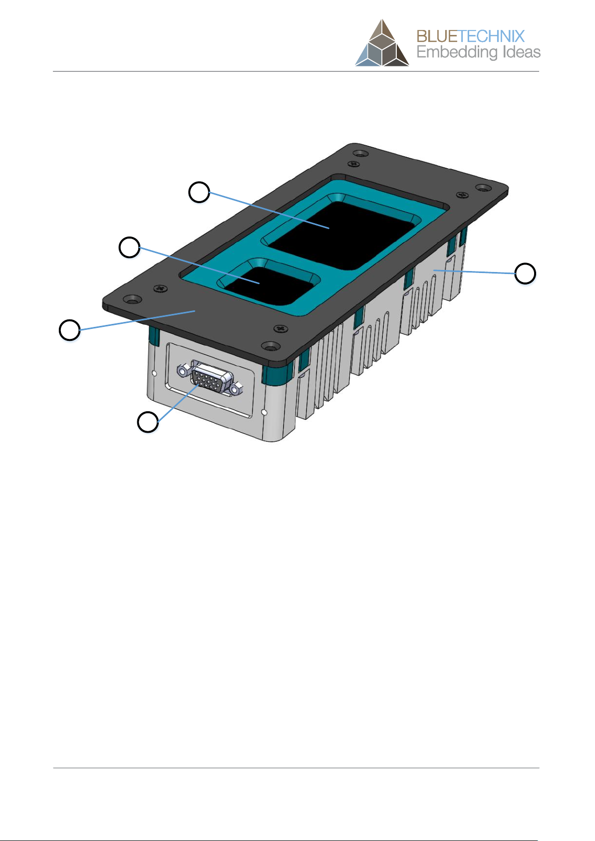
a
b
c
d
e
Figure 2-1 Argos3D-P220 components
a. Case
b. Cover plate (can be removed by unscrewing)
c. Viewing window for 3D sensor
d. Viewing window for illumination module
e. IP67 compliant connector
Hardware User Manual - Argos3D-P220 Last change: 2 August 2018
Version 5
© BECOM BLUETECHNIX 2018 Page 9 | 21
3Mechanical Description
3.1 Dimensions
All dimensions are in mm, tolerance +/-0,2mm.
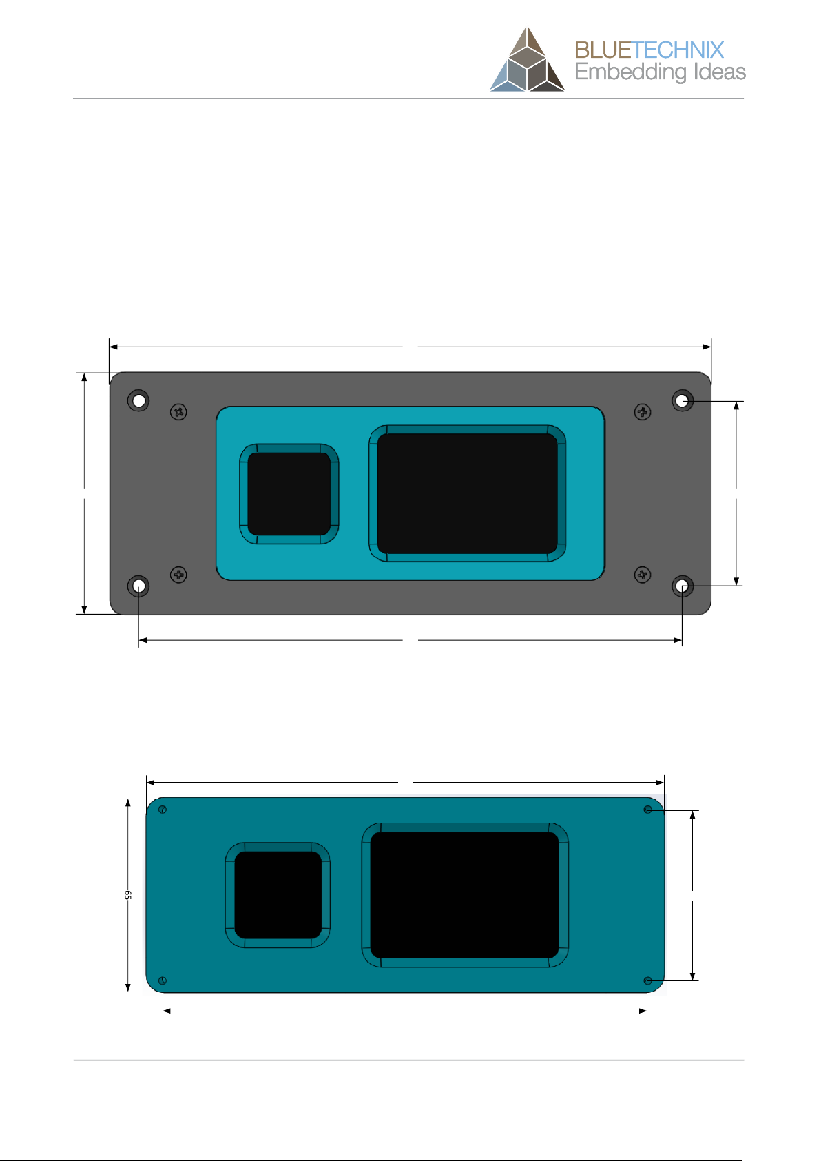
3.1.1 In-wall mounting with cover panel
Please use M4 screws for in-wall mounting using the cover panel.
85
210
190
65
Figure 3-1: Dimensions for in-wall mounting with cover panel
3.1.2 Top view
Top mounting hole size: M3
57
173
162
Figure 3-2: Top view dimensions without cover panel

Hardware User Manual - Argos3D-P220 Last change: 2 August 2018
Version 5
© BECOM BLUETECHNIX 2018 Page 10 | 21
3.1.3 Front view
Front mounting hole size: M3
65
21
19
13
6 6
Figure 3-3: Front view without cover panel
3.1.4 Back view
Back view mounting hole size: M3
65
13
66
Figure 3-4: Back view without cover panel
Hardware User Manual - Argos3D-P220 Last change: 2 August 2018
Version 5
© BECOM BLUETECHNIX 2018 Page 11 | 21
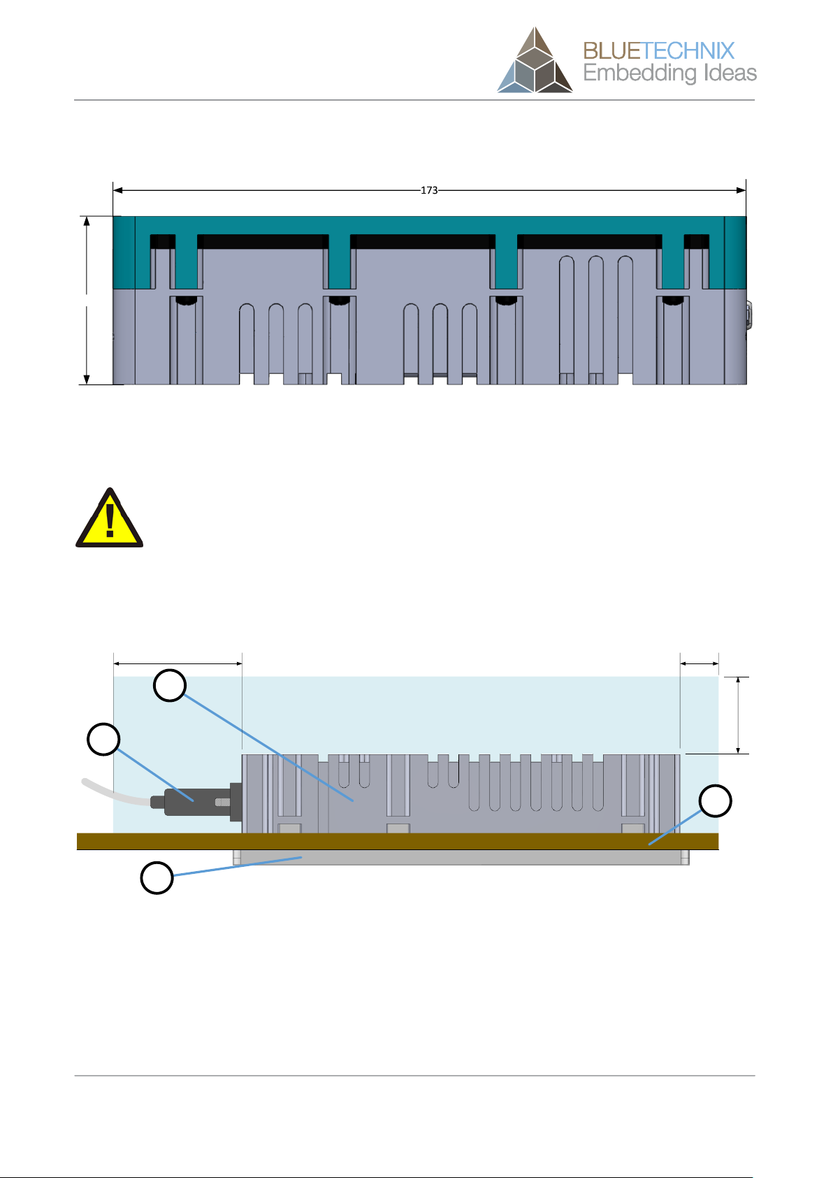
3.1.5 Side view
46
Figure 3-5: Side view without cover panel
3.1.6 Mount Spacing
Caution
Case may become hot!
The user is responsible to take care for an appropriate cooling.
To prevent the Argos3D-P220 from overheating, it is strongly recommended, to keep away nearby objects.
This guarantees a constant airflow for proper cooling. This bounding box may be violated, when other
cooling techniques are provided.
b
a
30,0
15,050,0
c
d
Figure 3-6: Bounding box
a. Argos3D-P220 Case
b. Argos3D-P220 Cover plate
c. Mating IP67 connector
d. Wall or mounting panel

Hardware User Manual - Argos3D-P220 Last change: 2 August 2018
Version 5
© BECOM BLUETECHNIX 2018 Page 12 | 21
4Interface Description
4.1 Signal naming
Signal names are usually written in capital letters. They are noted in positive logic (positive asserted). If the
signal is negative asserted an “n” will be added as prefix to the signal name.
Type:
The type describes the electrical characteristics of the signal. The following types are available:
•I Input
•O Output
•DN Negative Differential I/O
•DP Positive Differential I/O
•P Power supply
•3.3V TTL TTL compatible signal with 3.3V high level and 0V low level.
•50V tolerant Accepts input voltage levels up to 50V (2.5V high voltage threshold)
4.2 Connector Numbering
Figure 4-1: Connector Pin Numbering
4.2.1 Connector description
No.
Signal
Type
Description
1
ETH-B_N
DN
Ethernet Lane B
2
ETH-B_P
DP
Ethernet Lane B
3
GND
P
DIO Reference Ground
4
DIO
IO (50V tolerant)
Digital I/O Signal
5
V+
P
Positive Power Supply
6
ETH-C_N
DN
Ethernet Lane C

Hardware User Manual - Argos3D-P220 Last change: 2 August 2018
Version 5
© BECOM BLUETECHNIX 2018 Page 13 | 21
No.
Signal
Type
Description
7
ETH-C_P
DP
Ethernet Lane C
8
ETH-D_N
DN
Ethernet Lane D
9
ETH-D_P
DP
Ethernet Lane D
10
nTRIGGER
IO (3V3 TTL)
Trigger Input
11
ETH-A_N
DN
Ethernet Lane A
12
ETH-A_P
DP
Ethernet Lane A
13
GND
P
DI Reference Ground
14
DI
I (50V tolerant)
Digital Input Gignal
15
V-
P
Power Ground
Table 4-1: Connector Description
4.2.2 Power supply
The power supply pins are protected against wrong polarity.
Voltage range: 16V to 52V.
Note
Use inherently limited power sources only!
4.2.3 DIO
The digital Input-Output interface has an optical isolated input and output stage. Driven by the GPIOs 1
(output) and GPIO 3 (input). See the Software User Manual specifications for GPIO functionality.
The output stage is a solid state relais, and gives the possibility to use the output as a simple switcher. The
current is limited to 200mA.
If this interface is used as input, the corresponding output must be set to logically 0. Otherwise the input is
constantly shorted. The maximum LOW input detection voltage is 2V, the minimum HIGH input detection
volte is 5V.
4.2.4 Trigger In
The trigger Input is not optically isolated to minimize the propagation delay. But the input is protected
against 50V clamp voltages. A standard 3.3V TTL signal should be used.
4.2.5 RS485 Mounting Option
For some Applications a RS485 communication could be needed. Therefore the internal hardware could be
modified to route the RS485-A and –B signals to the connector in state of DI (RS485-A) and DIGND (RS485-
B).
Ask BECOM BLUETECHNIX for custom modifications.
Hardware User Manual - Argos3D-P220 Last change: 2 August 2018
Version 5
© BECOM BLUETECHNIX 2018 Page 14 | 21
4.3 Mating Parts
The mating IP67 connector is an A-HDS15-HOOD-WP from ASSMANN WSW components GmbH and
available for purchase e.g. at Digi-Key.
4.3.1 Interconnection cable
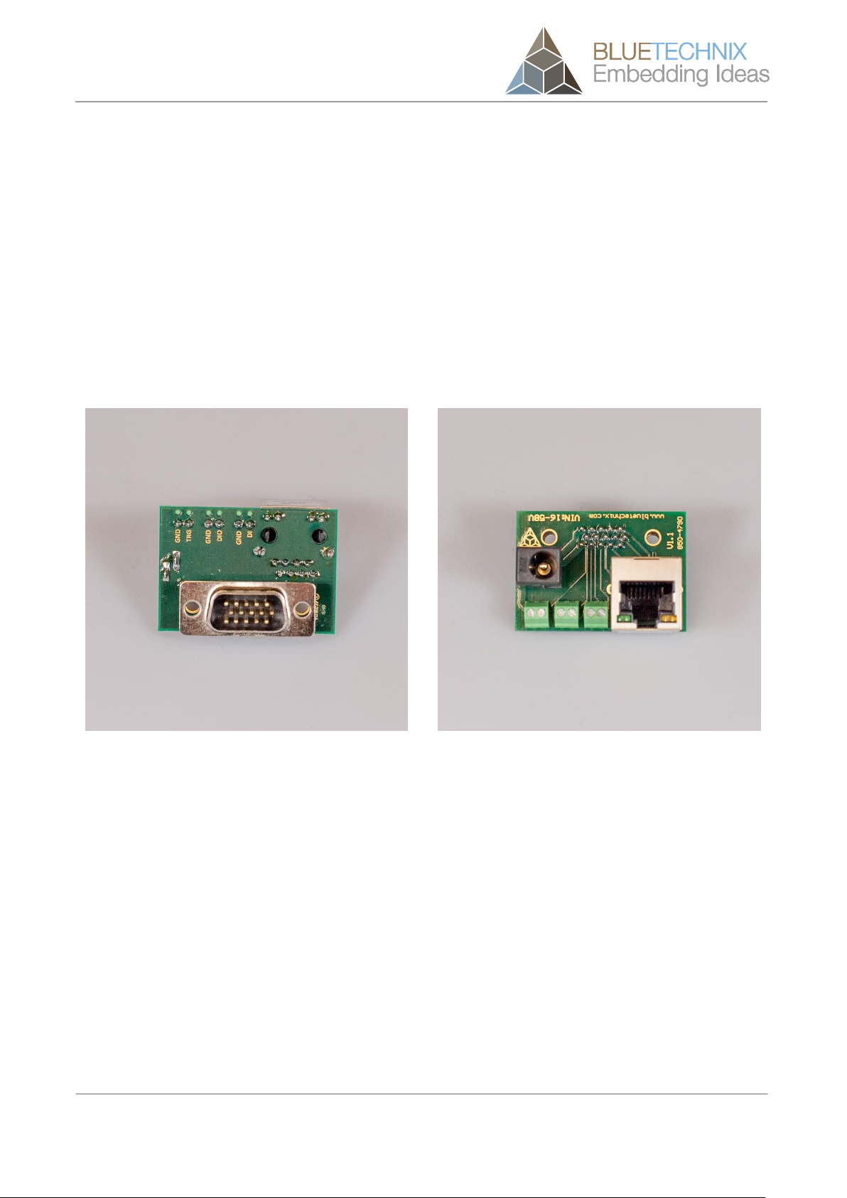
4.3.2 Development Adapter
For development purposes there is an adapter available with standard Ethernet RJ45 interface and a 2.1mm
DC power supply socket.
Figure 4-2: Adapter for Argos3D-P220
4.3.3 Interconnection Adapter
For interconnection there is an adapter available with standard Ethernet RJ45 interface and 2 pole headers
for IO and power supply.
Figure 4-3: Interconnection adapter for Argos3D-P220

Hardware User Manual - Argos3D-P220 Last change: 2 August 2018
Version 5
© BECOM BLUETECHNIX 2018 Page 15 | 21
5Software
5.1 Firmware
For a description of the firmware related interfaces, protocol descriptions, register settings, etc. please refer
to the Software User Manual.
5.2 Demo Application
For the first evaluation of the camera and to evaluate different settings and configurations a .NET demo
application for Microsoft Windows is provided: BLT-ToF-Suite. The demo application can be downloaded
from our support web site support.bluetechnix.com.
5.3 Getting Started Software Development Example
To facilitate the integration of the Argos module in your own application a getting started example will be
available on our download site. Please refer to our support site support.bluetechnix.com.

Hardware User Manual - Argos3D-P220 Last change: 2 August 2018
Version 5
© BECOM BLUETECHNIX 2018 Page 16 | 21
6Appendix
6.1 Operating Conditions
Symbol
Parameter
Min
Typical
Max
Unit
VIN
Input supply voltage3)
16
24
52
V
IIN
Average Input current 1)
0,66 1)
1,5
A
T
Operating Temperature 2)
-20
502)
°C
T
Storage Temperature
-40
+125
°C
FITP4)
Frame-rate Integration Time Product
950
Table 6-1: Operating Conditions
1) Note
Valid for a frame-rate of 30fps and an integration time of 3500µs. The input current depends on
the applied frame-rate and integration time.
2) Note
The maximum operating temperature depends on the frame-rate and integration time.
3) Note
The connector is used as section point.
6.1.1 Input current
The average input current depends on the selected frame-rate (fps) and the integration time (tINT). The
following figure shows typical values. The values on the x axis shows the FITP which has been calculated
with the following equation:
Figure 6-1: Input current @24V depending on frame-rate integration time product
0,00
0,20
0,40
0,60
0,80
1,00
1,20
1,40
1,60
0 200 400 600 800 1000
Current consumption [A]
FITP
Current consumption depending on FITP

Hardware User Manual - Argos3D-P220 Last change: 2 August 2018
Version 5
© BECOM BLUETECHNIX 2018 Page 17 | 21
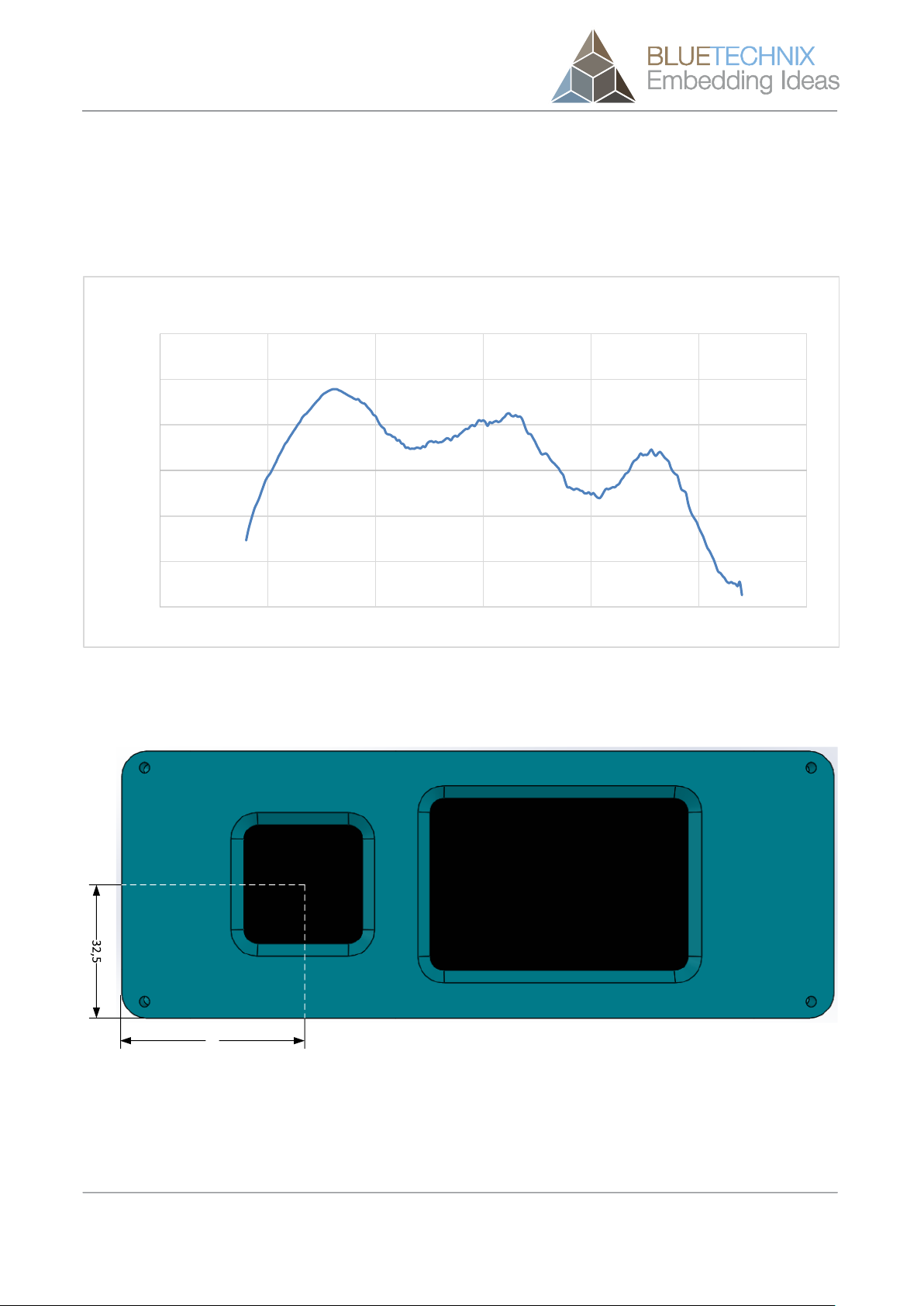
6.1.2 Temperature at the case
The following figure shows the expected case temperature @ 25°C ambient temperature depending on the
frame-rate integration time product (FITP). The FITP has been calculated as follow:
Figure 6-2: Expected cooling plate temperature depending on frame-rate integration time product
The temperature on the casing can be reduced by mounting an additional heat sink on the cooling plate.
Caution
The user is responsible to take care for an appropriate cooling if the Argos camera is mounted
into a case.
Caution
Be careful to not stress the device beyond the limits, otherwise you may damage the device.
6.2 Optical Characteristics
Symbol
Parameter
Min
Typical
Max
Unit
#LEDs
Nr. of LEDs
6
ΛCENTROID
Centroid-Wavelength of Illumination
850
nm
0
10
20
30
40
50
60
70
0 100 200 300 400 500 600 700 800 900
Temperature [°C]
FITP
Casing temperature depending on FITP

Hardware User Manual - Argos3D-P220 Last change: 2 August 2018
Version 5
© BECOM BLUETECHNIX 2018 Page 18 | 21
Symbol
Parameter
Min
Typical
Max
Unit
Δλ
Spectral Bandwidth
30
nm
Ie
Radiant intensity
TBD
W/sr
FoVH
Horizontal Field of View
90
Deg
FoVV
Vertical Field of View
67
Deg
6.3 Performance
6.3.1 Environmental Conditions
All the following measurements have been acquired at the following constant environmental conditions.
Parameter
Value
Temperature
23 °C
Humidity
35 %
Ambient light
500 Lux
Modulation Frequency
22,1 MHz
Frame-rate
30 fps
Table 6-2: Environmental Specification
6.3.2 Precision
The following graph shows the standard deviation over 100 samples.
Figure 6-3: Precision
0
2
4
6
8
10
12
14
500 1000 1500 2000 2500 3000 3500
Standard Deviation [mm]
Real Distance [mm]
Precision
Hardware User Manual - Argos3D-P220 Last change: 2 August 2018
Version 5
© BECOM BLUETECHNIX 2018 Page 19 | 21
6.3.3 Accuracy
The following figures has been determined by a frame-rate of 30fps and an integration time of 3,5ms with a
reflectivity of 90%.
Figure 6-4: Accuracy
6.4 Sensor Location
44
Figure 6-5: Location of optical center of sensor
-15
-10
-5
0
5
10
15
500 1000 1500 2000 2500 3000 3500
Measurement Error [mm]
Real Distance [mm]
Accuracy

Hardware User Manual - Argos3D-P220 Last change: 2 August 2018
Version 5
© BECOM BLUETECHNIX 2018 Page 20 | 21
7Support
7.1.1 General Support
General support for products can be found at BECOM BLUETECHNIX’ support site
Support Link
https://support.bluetechnix.at
7.2 Related Products
•TIM-UP-19kS3-ETH
•LIM-U-LED-850-6
Table of contents
Other Blue Technix Measuring Instrument manuals


