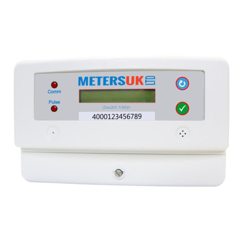
Meters UK 3MB100 User manual

3 MB 100
METERSUK
L
T
D
User ManualSmart Energy Metersales@meters.co.uk 01524 555 929INDEX1. Safety notice2. Package Contents3. Technical Description 3.1 Product Description 3.2 Performance criteria 3.3 Meter specification4. Dimensions 5. Wiring diagrams6. Meter reading7. Main features 7.1 Consumption Indicator 7.2 Reading the Meter 7.3 Pulse Output 7.4 Far Infrared Interface 7.4 Communication Port8 Programming 8.1 Password verify 8.2 CT Rate setting 8.3 Baud rate setting 8.4 ID/Address Setting9. Technical support3. TECHNICAL DESCRIPTION3 MB 100 • Direct Connection • M-Bus • Pulse output
DYNAMiTE
SmartLink
KEY FEATURES• Three Phase metering• Standard DIN rail format (DIN43880)• CI.1 Accuracy EN50470• LCD display, 6 integer 1 decimal• Large display LCD• Smart communication port, M-Bus output• Isolate pulse output and IR (DIN43864)• Direct metering up to 100A • M-bus communication• Front Panel Programming• Memory back-up (EEprom)• 7 DIN module size
METERSUK
L
T
D
1. SAFETY NOTICEThe smart energy meter 3 MB 100 does not require special mechanical or electrical tools for its installation. Mounting position (with any angle of tilt) has no effect on the measurement functions of the meter.Connection of the meter must follow the wiring diagram. Incorrect connection of the meter to the electricity network will cause a major display problem and can also cause serious damage to the meter. Before connecting the meter, ensure the local conditions of the energy supply is consistent with the information under the model number of the meter. Preferably use shielded cables. Make sure that all connection cables are not damaged during the installation of the meter and not energized or showing any non-mechanical stress.Repairs to the meter are to be made by a qualified electrician only. PLEASE NOTE: The capacitors in the meter may still be charged after the meter is disconnected for all power.2. PACKAGE CONTENTSThree phase, electronic energy meter Instructions for assembly; ID setting; Baud rate setting; Password setting

User Manual3.3 METER SPECIFICATION
3MB100
3.2 PERFORMANCE CRITERIAOperating humidity Storage humidity Operating temperature Storage temperature Humidity International standard Accuracy class Protection against penetration of dust and water Insulating encased meter protective classConnection area main terminalsCurrent terminals flexible 1×mm² ≤ 75%≤ 95%-5°C to + 45°C (3K5)-25°C to + 55°C (3k6)75% yearly average95% on 30 days per yearEN50470-3 & IEC62053-21CI.1IP510-16mm²0 - 2.5mm²
Direct ConnectionCurrent (A)- Lref- Ltr- Lmax- Lmin- IstGeneral dataFrequency (Hz) Memory back-up upperlowerPulse outputPulse width(ms) Pulse Value = 1kWhLED constant Width x Height x Depth (mm)126 x 104.5 x 6050/60EEpromTerminal 960 CCover 650 CABS+PC
400
80
400 PULSESABS+PC100A1A0.5A40mAEnvironment resistance to heat and fire3X230/400V70%UnPower consumption of current circuits (VA)Power consumption of voltage circuits(W)10A< 0.01< 1.3WVoltage4. DIMENSIONS

User Manual5. WIRING DIAGRAMS
3MB100
82215102417121914219231611181320
1357246
LINE 1 IN
LINE 1 OUTLINE 2 OUTLINE 3 OUT
LINE 2 INLINE 3 INNEUTRAL IN
21 + 22 = M-Bus Communication 23 + 24 = Pulse Output (23 + | 24 - ) Pulse Width : 80m/secPulse Constant: 400 Pulse = 1 kWh
M-BUS CONTACT

User Manual5A. TYPE OF CABLE TO USEThe M-Bus uses two wire cables which are going from the M-Bus Master / Repeater to each M-Bus device (bus structure). The M-Bus is polarity independent and needs no line termination resistors at the end of the cables.Any cable type may be used as long as the cable is suitable for 36 V / 500 mA.Shielding is not necessary and not recommended since the capacitance of the cable should be minimized.In most cases a standard telephone cable is used which is a twisted pair wire with a diameter of 0.5 mm each (2 x 0.8 mm is also suitable). This type of cable should be used for the main wiring. For the wiring to the meters from the main wiring (last 1 .. 5m to the meter) a cable with smaller diameter may be used. 5B. M-BUS BASICSThe topology of the M-Bus network is (almost) arbitrary. Only the ring topology as shown should be avoided. In general the length of the cables should be minimized and a mixture between star and bus topology should be used. The limiting parameters in M-Bus networks are mainly the cable resistance and the cable capacitance plus the capacitance of the devices (= bus capacitance). Cable resistance will cause, a bus voltage drop. The maximum drop may not be more than 11 V .. 12 V, as the minimum bus voltage at any device must not be lower than 24 V (36 V – 24 V = 12 V).The cable resistance, therefore, limits the maximum possible cable length from the MBus Master / Repeater to the device with the largest distance away from it (largest cable segment). The cable segment length is the distance from the M-Bus Master to the M-Bus device furthest away.NOTE: The given maximum cable segment length takes into account only the bus resistance and not the bus capacitance. Therefore, some of the cable lengths in the table may not be possible in reality.The cable capacitance plus the capacitance of the M-Bus devices (= bus capacitance) is responsible for sloppy signal edges. Therefore, the bus capacitance limits the maximum data transfer rate of the M-Bus. The M-Bus Master is able to drive approx. 0,8 µF at a baud rate of 300 baud.
3MB100
5C. BAUD RATE & BIT RATESBit rate is a measurement of the number of data bits (that's 0's and 1's) transmitted in one second. A figure of 2400 bits per sec means 2400 zeros or ones can be transmitted in one second, hence the abbreviation 'bps'. Baud rate by definition means the number of times a signal in a communications channel changes state.Common Settings for M-bus - 300 or 2400. Parity (Error Checking) is EVEN or NONE.ALL items MUST have the same settings otherwise they CANNOT communicate.ance:ance:Current capacitance of one M-Bus device:Current capacitance of one M-Bus device:ance)ance)

User Manual
3MB100
7. MAIN FEATURES7.1 Consumption indicationOn the front panel, there are five LED’s. 1. Line 1 2. Line 2 3. Line 3 4. Reverse Current 5. Active Energy Pulse Light.7.2 Reading the meter6+1 LCD display is used for recording energy reading and the system cannot be reset to zero. Each digit is based on 10 units and each unit is in kWh.When switched on, the meter will run through all the current default settings. Each screen will display for 1 second. Rs485, PC software or a hand-held unit can also be used to read the power consumptionFULL SCREEN DISPLAY :Active Energy :Baud Rate :Version No
735.3.0999999.9bd 240088888.8.8
7.3 Pulse outputSmart din rail energy meter is equipped with a pulse output which is fully separated from the inside circuit. That generates pulses in proportion to the measured energy. They are test pulse output (pins 23&24). Usually, the test pulse output is used as testing accuracy or reading purpose in close quarters., passive transistor output requiring an external voltage source for THE TEST PULSE OUTPUT IS A POLARITY DEPENDANTcorrect operation. For this external voltage source, the voltage (Ui) should be 5-27V DC, and the maximum input current (Imax) should be 27mA DC. To connect the impulse output, connect 5-27V DC to connector 25 (anode), and the signal wire (S) to connector 24 (cathode). The meter pulses is indicated on the front panel.+7.5 Communication portSmart meter has equipped communication port, we can program the meter’s operation data or reading via these 2 ports (Pin26 pin27). There are two options for the communication com, Rs485 or M-Bus
Protocol EN13757-3, EN1434-3Data format8 data bit,Even,1 stop bitBaud rate 300, 2400 (default), 9600Address range1-250 User settable 380m 250PCS 3600m 64PCSCable JYSTY (nx2x0.8)Bus loading
≤≤6. METER READINGThe viewing angle Operator meter should be at 45°.

User Manual8.1 Password Verification“PA” stands for “Password”. ”0000” are the digits of the password. Set the password by pressing the “Down” button to decrease the digit value, or “Up” to increase the value.Password is 8888. Press the “ ” eight times (to get to 8) press “SET” button and the marker will move to the next digit whichshould automatically default to 8. Press “SET” four times to move onto the next setting.8.2 ID SettingAfter entering the password, the meter will ask for the address range. Enter 1 if you are not using Mbus.Example below ”Id 00” shows that the current ID address is 00 (the ID address is hex code)Address should be between 1 - 250Use the “Down” button to decrease the digit or ”Up” to increase the digit value. Press the “SET” button to save the digit and move onto the next digit.8.3 Baud rate settingPress “SET” button to bypass entering the Baud rate.Press “Down” and “Up” buttons to select the communication baud rate, press “SET” button to save the setup.The interface will enter CT setup.Note:The default baud rate will be set at 1200 bps
3MB100
ID 00
sales@meters.co.uk | White Lund Industrial Estate Lancaster LA3 3BT | 01524 555 9298. PROGRAMMINGBy holding the keys “SET” pressed for at last 3 seconds The meter will go into programming mode.
Baud Rate = bits per second. This is the rate that devices exchange information online (on the RS485 network).All devices MUST BE SENT at the SAME rate otherwise they cannot communicate.Common Baud rate settings for M-Bus : 300; 2400
PA 0000
L1
L3
rev
L2
000375.5
000123456789
EM735-Mod
I EC 620 53-2 1 :2 0163x2 30/ 400V 3x1 0(1 00)A 50/ 60Hz
METERSUK
L
T
D
bd 2400

User Manual
3MB100
sales@meters.co.uk | White Lund Industrial Estate Lancaster LA3 3BT | 01524 555 929PASSWORD SETTING:The meter will display the current password. You DO NOT have to change the current password (8888), however if you wish to change it use the “Up” and “Down” buttonsto change each digit. Once happy with the chosen number press “SET” button to move onto the next digit.Once complete, the meter will automatically save the password after 30 seconds or when powered off.PLEASE NOTE:It is important to take a note of the new password as one cannot bypass the system. If the password is not crucial, leave thepassword as the default (0000).9. TECHNICAL SUPPORTAny questions, please contact Meters UK 01524 555 929OTHER:Branches must be no longer than 1200m. Longer branches could cause signal reflections and generate disturbances andconsequent errors in the reception data.Max. distance of main cable: 1.2kmMax number of devices : 64 including the master
PA-0000
Table of contents
Other Meters UK Measuring Instrument manuals

Meters UK
Meters UK SmartLink 45 User manual

Meters UK
Meters UK SmartLink45 4000123456789 User manual
Meters UK
Meters UK SmartLink45 4000123456789 User manual

Meters UK
Meters UK SmartLink 45 User manual

Meters UK
Meters UK EM606 M-Bus User manual

Meters UK
Meters UK SmartLink45 User manual

Meters UK
Meters UK MOD3CT User manual