manuals.online logo
Brands
  1. Home
  2. •
  3. Brands
  4. •
  5. Bluebird
  6. •
  7. Motorhome
  8. •
  9. Bluebird Wanderlodge Wide Body Pusher 1989 User manual

Bluebird Wanderlodge Wide Body Pusher 1989 User manual

e
$L~b
~
..A-~
\ ' - g00 -99~-Co~~{
1989
Wanderlodge
Wide ·Body
Pusher
DearWanderlodgeOwner:
Congratulationson beingthe new ownerof thefinest and
safestproductionmotorcoachin the world-the BlueBird
Wanderlodge.
We have all workedhardto makeyour new Wanderlodgethe
bestwe haveeverbuilt. At the sametime, we havealso
recognizedyour needfor moreand betterinformationabout
your coachso you canenjoy it to thefullest. To that end, we
havepreparedthis manualfor your information.We hopeyou
find it helpful as you acquaintyourselfwith themany luxurious
featuresof your new coach.
I want to personallythankyou for your businessand invite
you to take advantageof our Bird's Nest parkand clubhouse
wheneveryou canvisit us in Ft. Valley.
Thankyou again, and welcometo our Familyof Friends!
AP~
BillMilby
Vice-President/GeneralManager
YOUR LIMITED WARRANTY ON YOUR NEW
wander lodge
Whoare the parties to this Warranty?
Blue Bird Wanderlodge, a division ofBlue Bird Body Com-
pany, gives this Warranty. The terms "we," "us," and "our"
in this Warranty refer to that division. The Warranty extends
to the owner of the Wanderlodge <t.The terms "you" and
"your" in this Warranty refer to the owner.
What parts are covered?
This Warranty covers all parts of the Wanderlodge e that
are made or bought by our factory and installed there, those
major power train components that are warranted from other
manufacturers are not covered by this Warranty, such as en-
gine, transmission and batteries . Those separate warranties
are contained in the owner's package furnished to you by your
dealer at the time ofdelivery. Our Warranty also does not in-
clude parts or accessories which you or your dealer bought or
install ed.
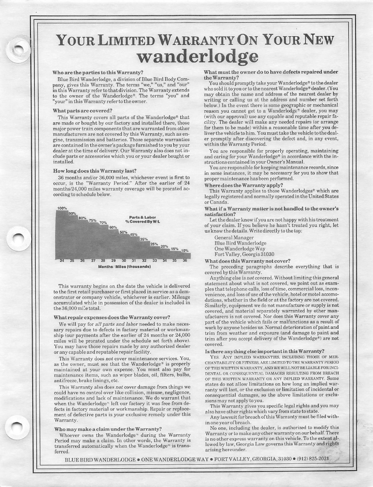
How long does this Warranty last?
36 months and/or 36,000 miles, whichever event is first to
occur, is the "Warranty Period." After the earlier of 24
month s/24,000 miles warranty coverage will be prorated ac-
cording to schedule below.
Parts & Labor
% Covered By W/L
Month aI Miles (thousands)
This warranty begins on the date the vehicle is delivered
to the first retail purchaser or first placed in service as a dem-
onstrator or company vehicle, whichever is ear lier. Mileag e
accumulated while in possession of the deal er is included in
the 36,000 mi:e total.
What repair expenses does the Warranty cover?
We will pay for all parts and labor needed to make neces-
sary repairs due to defects in factory materia l or workman-
ship (our payments after the ear lier of 24 month s or 24,000
miles will be prorated under the schedule set forth above).
You may have those repairs made by any author ized dealer
orany capable and reputable repair facility.
This Warranty does not cover maintenanc e services. You,
as the owner, must see that the Wanderlodge• is properly
maintained at your own expense. You must also pay for
maintenance items, such as wiper blades, oil, filters, bulbs,
antifre eze,brake linings, etc.
This Warranty also does not cover damage from things we
could have no control over like collision, misuse, negligence,
modifications and lack of maintenance . We do warrant that
when the Wanderlodge • left our factory it was free from de-
fects in factory material or workmanship. Repair or replace-
ment of defective parts is your exclusive remedy under this
Warranty.
Whomay make a claim under the Warranty?
Whoever owns the Wanderlodge • during the Warranty
Period may make a claim. In other words, the Warranty is
transferred automatically when the Wander lodge'"'is trans-
ferred.
What must the owner do to have defects repaired unde r
the Warranty?
You should promptly take your Wanderlodge e to the dealer
who sold it toyou or to the nearest Wanderlodgee dealer. (You
may obtain the name and address of the nearest dealer by
writing or calling us at the address and number set forth
below.) In the event there is some geographic or mechanica l
reason you cannot get to a Wanderlodge'!>dealer, you may
(with our approval) use any qi.pable and reputable repair fa.
cility. The dealer will make any needed repairs (or arrange
for them to be made) within a reasonable time after you de-
liver the vehicle to him. Youmust take the vehicle tothe deal-
er promptly after discovering the defect and, in any event,
within the Warranty Period.
You are responsible for properly operating, maintain ing
and caring for your Wanderlodge t in accordance with the in-
struct ions contai ned in your Owner's Manual.
You are responsible for keeping maintenance records,since
in some instances, it may be necessary for you to show that
proper maint ena nce hasbeen performed.
Where does the Warranty apply?
This Warranty applies to those Wanderlodges~ which are
legally registered and normally operated in the United States
or Canada. ·
What if a Warranty matter is not handled to the owne r's
satisfaction?
Let the dealer know ifyou are not happy with his treatment
of your claim. If you believe he hasn't treated you right, let
us know the details. Write directly tothe top:
General Manager
Blue Bird Wanderlodge
One Wanderlodge Way
Fort Valley,Georgia 31030
Whatdoes this Warranty not cover?
The preceding paragraphs describe everything that is
covered bythis Warranty.
Anything else isnot covered. Without limiting this general
state ment about what is not covered, we point out as exam-
ples that telephone calls, lossof time, commercial loss,incon-
venience, and loss ofuse ofthe vehicle, hotel or motel accomo-
dations, whether in the field or at the factory are not covered.
Similarly, equipment we do not manufacture or supply is not
covered, and material separately warranted by other man-
ufacturers is not covered. Nor does this Warranty cover any
part of the vehicle which fails or malfunctions as a result of
work by anyone besides us. Normal deterioration ofpaint and
trim from weather and exposure (and damage to paint and
trim after you accept delivery of the Wanderlodge-9)are not
covered.
Is there anything else important in this Warranty?
YES . ANY IMPLIF,I) WARRANTIES. INCLUDING THO SE OF MER-
CHANTARll ,ITY OR FITNESS, ARE LIMITED TO THE WARRANTY PERIOD
OF THI S WR\ITF,N WARRANTY. AND WE WlLL NOT BE LIABLE FOR INCI-
DENTAi. OR CONS EQUENTIAi. DAMAGES RESULTING FROM BREACH
OF THIS WRIITF.N WARRANTY OR ANY LMPLIED WARRANTY . Some
states do not allow limitation s on how long an implied war-
ranty will last, or the exclusion or limitation ofincidental or
consequent ial damages , so the above limitation s or exclu-
sions may not applytoyou.
This Warranty gives you specific legal rights and you may
also have other rights which vary from state to state.
Any lawsuit forbreach ofthis Warranty must be filedwith-
in one year ofbreach.
No one, includin g the dealer, is aut horized to modify this
Warranty or to make any other warranty on our behalf.There
is no other express warranty on this vehicle. To the extent al-
lowed by law, Georgia Law governs this Warranty and rights
arising hereunder .
BLUE BIRD WANDERLODGE • ONE WANDERLODGE WAY• FORTV ALLEY,GEORGIA,31030 • l912l825-2021
e
Table of Contents
Section I - Introduction
Content s . . . . . . . . . . . . . . . . . . . . . . . . . 1-1
Checkl ists . . . . . . . . . . . . . . . . . . . . . . . . 1-1
Citizen 's Band Transceiver . . . . . . . . . . . 1-3
Hot Weather Operation . . . . . . . . . . . . . . 1-3
Cold Weather Operation . . . . . . . . . . . . . 1-4
Campgr ound Courtesy . . . . . . . . . . . . . . 1-4
Insurance . . . . . . . . . . . . . . . . . . . . . . . . . 1-4
Safety Considerations . . . . . . . . . . . . . . . 1-4
Vehicle Loading . . . . . . . . . . . . . . . . . . . . 1-6
Economical Driving . . . . . . . . . . . . . . . . . 1-7
Engine Operating Hints . . . . . . . . . . . . . . 1-7
Fuel and Additives . . . . . . . . . . . . . . . . . . 1-7
Lubrication and Mai"ntenance . . . . . . . . . 1-7
Travel ing in Your Motorhome .... .. ... 1-8
General Storage Notes . . . . . . . . . . . . . . 1-8
Emergency Assistance . . . . . . . . . . . . . . 1-8
Section II -Opera tion
Instrument ation . . . . . . . . . . . . . . . . . . . . 2-1
Upper Dash Panel . . . . . . . . . . . . . . . . 2-2
Lower Dash Panel . . . . . . . . . . . . . . . . 2-4
Air Suspension System . . . . . . . . . . . . 2-6
Shifter Panel . . . . . . . . . . . . . . . . . . . . 2-7
Upper Right Hand Dash Panel . . . . . . 2-8
Lower Right Hand Dash Panel . . . . . . 2-9
Closed CirctuitTV
Monitor Panel . . . . . . . . . . . . . . . . . . . 2-9
Monitor Control Panel . . . . . . . . . . . . . 2-9
C.B.,Stereo and
lnveter Panel . . . . . . . . . . . . . . . . . . . . 2-9
Overhead Control Center . . . . . . . . . 2-1O
UHF/VHF Televi sion Receiver ..... 2-10
Pilot's Area Overhead Dash . . . . . . . 2-1
O
Co-Pilot's Area Overhead Dash . . . . 2-11
Steering Column Area . . . . . . . . . . . . 2-12
Floor Controls . . . . . . . . . . . . . . . . . . 2-13
Radar Detector . . . . . . . . . . . . . . . . . 2-14
Seat Controls . . . . . . . . . . . . . . . . . . . 2-14
CCTV and Line Up Operation . . . . . . . . 2-14
TV Antenna and Rotator System . . . . . 2-14
CB Transceiver Unit ............... 2-15
Diesel Engineff ransmission Operation . 2-15
WLWB
To Start Engine . . . . . . . . . . . . . . . . . 2-15
Remote Engine Starting ......... . 2-15
To Stop Engine .. .. ............ . 2-16
Using the Allison Transmis sion
Brake/Retarder . . . . . . . . . . . . . . . . 2-16
Trailer Hitch . . . . . . . . . . . . . . . . . . . . 2-16
Towing ......... . ... . .......... 2-16
Transmission Operation . ......... 2-17
Driving Tips . . . . . . . . . . . . . . . . . . . . . . 2-17
Accelerator Control . . . . . . . . . . . . . . 2-17
Downshift Control . . . . . . . . . . . . . . . 2-17
Transmission Oil Temperature .... . 2-17
General Information- Detroit Diesel
Engines . . . . . . . . . . . . . . . . . . . . 2-17
Racor Fuel Filter . . . . . . . . . . . . . . . . 2-18
Fuel Line Heater . . . . . . . . . . . . . . . . 2-18
Leveling Jacks Controls . . . . . . . . . . 2-18
Section Il l - Living Area Facilities
Sofa .... .. ....... ... ... ...... ... . 3-1
Dinette Area . . . . . . . . . . . . . . . . . . . . . . 3-1
Galley Facilities . . . . . . . . . . . . . . . . . . . . 3-1
Refrigerator . . . . . . . . . . . . . . . . . . . . . 3-1
Gas Cooktop . . . . . . . . . . . . . . . . . . . . 3-2
Microwave/Convection Oven .. . ..... 3-3
CORIAN Counter Tops .... ...... ..
3-4
Food Center . . . . . . . . . . . . . . . . . . . . 3-4
Bathroom .. .............. .. ... . ... 3-4
Vent and Exhaust Fans ....... ... . ... 3-5
Heating Systems . . . . . . . . . . . . . . . . . . . 3-5
Air Conditioners .. ... ... ... . ........ 3-7
Systems Monitoring and Control Panel . 3-7
LP Gas Le::1kage Detector . . . . . . . . . . . . 3-9
Electronic Door Chime . . . . . . . . . . . . . . 3-9
Portable Fan . . . . . . . . . . . . . . . . . . . . . 3-1
O
Security Timer . . . . . . . . . . . . . . . . . . . . 3-10
Burglar Alarm/Anti-Theft Features .... 3-10
Fire Extinguisher . . . . . . . . . . . . . . . . . . 3-10
Smoke Detector . . . . . . . . . . . . . . . . . . . 3-10
Bedroom Overhead Panel . . . . . . . . . . . 3-10
L.P.G. Grill ........ . ............. 3-11
Stepwell Cover . . . . . . . . . . . . . . . . . . . 3-12
Section IV -Electrical Systems
12-Volt DC Supply System . . . . . . . . . . . 4-1
Battery Heaters . . . . . . . . . . . . . . . . . . 4-1
Battery Chargers . . . . . . . . . . . . . . . . . 4-1
DC Supply Monitors . . . . . . . . . . . . . . 4-2
AC Supply System . . . . . . . . . . . . . . . . . 4-2
Power Line Monitors . . . . . . . . . . . . . . 4-2
AC Circuit Breaker Panels . . . . . . . . . 4-~
Generator Operation . . . . . . . . . . . . . . 4-2
ShorelineOperation(CommercialPower) . 4-3
Troubleshooting .................. 4-4
Safeline Alarm . . . . . . . . . . . . . . . . . . . 4-4
Audio System Wiring . . . . . . . . . . . . . . . . 4-4
Electronic Master Switch . . . . . . . . . . . . . 4-4
Battery Jumper Terminals . ... ... . .. .. 4-4
Battery Storage in Freezing
Weather . . . . . . . . . . . . . . . . . . . . . . . . 4-4
•
e .
Section V - Water Distribution and
Drainage Systems
Water Supply and Distribution
System .. .. ..... .... .... . . . . . . . .
Commercial Water Hookup . .' . .. . . . .
Filling and Sanitizing ... .. .. . .. . .. .
Potable Water Distribution System .. . . .
Water Pump . .. .. ......... .
Water Purifier . . ..... .. .. . .... . . .
Water System Air Accumul ator
with Diaphragm . . . . ........ .. . .
Water Heater .. . ..... . . . . . ...... .
Outside Faucet .. . .. .. ... ..... ...
Drainage System ... .. ..... .... . ... .
Draining the Holding Tanks ...... . . .
Tank Level Detectors .. . . .. ... . . . .
Winterizing . .. .. . . . .. . . . . .. .... . .. .
Draining and Winter izing the
Fresh Water Supply System ... . . .
Draining the Ice-Make r .. . . ....... .
Section VI - LPG System
5-1
5-1
5-1
5-2
5-2
5-3
5-3
5-4
5-4
5-4
5-4
5-5
5-5
5-5
5-6
LPG Tank and Controls ......... . .
Fuel Requirements ........ . . .. . . .
'Filling the LP Gas Tank . ... .. . . . . .
LP Gas and Vapor Detectors . . . ... .
Regulator Pressu re ....... .... . .. .
6-1
6-1
6-1
6-2
6-2 '
Operation . . . . .... . .. . . ... .,. . .. . . . .
Checking for Leaks . . ........ . . .... .
LPG Consumption ........ .. . . .. . .. .
LPG System Wa rnings .... .. . . . .... .
Section VI I -Air Brake Systems
6-2
6-2
6-2
6-2
Operation . . . . . . . . . . . . . . . . . . . . . . . . . 7-1
Brake Failures ... . . ... . ... . .. .... 7-1
Additional Air Ope rated
Equipment . . .... .. . . ... ... . .. . . . 7-1
Compr essed Air System Air Dryer ... 7-2
Section VIII -Owner Maintenance Data
Specifications and Data . . . . . . . . . . . . . 8-1
Changing Whee ls/Tires . . . . . . . . . . . . . . 8-4
Check ing Torque on Dual
Wheels ... .... . .... . . . .. . .. ... 8-5
Battery Maintenance . . . . . . . . . . . . . . . . 8-5
Periodic Battery Checks and
Maintenance . . . . . . . . . . . . . . . . . . 8-6
Exterior Care . . . . . . . . . . . . . . . . . . . . . . 8-6
Interior Care . . . . . . . . . . . . . . . . . . . . . . 8-6
Fluid Level Checks . . . . . . . . . . . . . . . . . 8-6
Crankcase Oil Level . . . . . . . . . . . . . . 8-6
ii
Power Steering and Hydraul ic Cooling
Fan Reservoir Fluid Level . . . . . . . . 8-7
Transmission Fluid Level ... ,.. . . . . . 8-7
Importanc e of Proper Oil Level . . . . . . 8-7
Oil Check Proced ure . . . . . . . . . . . . . . 8-7
Hot Check . . . . . . . . . . . . . . . . . . . . . . 8-7
Cold Check . . . . . . . . . . . . . . . . . . . . . 8-7
Racor FuelFilterand Wate r
Separa tor System . . . . . . . . . . . . . . . . 8-8
Filter/Separato r Operation . . . . . . . . . . 8-8
In-Filter Fuel Heater . . . . . . . . . . . . . . 8-8
Water- In-Filter Alarm . . . . . . . . . . . . . . 8-8
Maintenance . . . . . . . . . . . . . . . . . . . . 8-8
Hydrau lic Cooling Fan . . . . . . . . . . . . . . . 8-9
Leveling Jacks Reservoir . . . . . . . . . . . . 8-9
Engine Air Filter Replacement . . . . . . . . 8-9
Engine Cooling System Refill . . . . . . . . . 8-9
Cooling System Additives . . . . . . . . . . . 8-1o
Windshield Washe rs .. ...... . . ... . . 8-10
Battery Jumper Terminals and
Jump-Star ting . . . . . . . . . . . . . . . . . . . 8-1o
Generator . . . . . . . . . . . . . . . . . . . . . . . 8-11
Mainten ance Schedu les . . . . . . . . . . 8-11
Generato r Troubleshooting . . . . . . . . 8-13
Generato r Overloads . . . . . . . . . . . . . 8-13
Generator Battery Charging . . . . . . . 8-13
Storage Proced ures . . . . . . . . . . . . . 8-13
Refrigerator . . . . . . . . . . . . . . . . . . . . . . 8-14
Toilet . .. . . .. .. .. .. ... . .. . . ...... 8-14
Water Pump ... . .. . . . ... . . .. .. .. . 8-14
Clock/Th ermometer Calibration
Procedu res . . . . . . . . . . . . . . . . . . . . . 8-15
Thermometer Calibration
Procedures . . . . . . . . . . . . . . . . . . . 8-15
Tub/Shower Mixing Valve .. .. .. . .. . . 8-15
Air Step Speed Adjustment . . . . . . . . . . 8-15
Section IX- General Information
Equipment Manufacturers
Section X- Diagrams
Section XI - Equipment Options
Awnings ..... . . . . . . . . . . . . . . . . ... . 11-1
Open Awning . . . . . .. .. . .. . . . . . . . 11-1
Close Awning . . . . . .. . . . .... . .. . 11-2
Fabric Care . . . ... . . .... . .. . . .. . 11-2
Washing ... . . . . .. . .... .. .... .. . 11-2
✓
Water Leaks . .. . .. . . .. . .. .... . . 11-2
Storm Precaut ions . . ..... . ... . . . . 11-2
Hardware and Mechanism
Maintenance . ... . . . . .. .... . . . 11-3
At the End of Each Season .. . . .. . 11-3
WLWB
J
e
Ice-Maker . . . . . . . . . . . . . . . . . . . . . . . . 11-3
Ice-Maker Operation . . . . . . . . . . . . . 11-3
Ice-Maker Maintenance . . . . . . . . . . . 11-3
Winterizing . . . . . . . . . . . . . . . . . . . . . 11-3
Kool-0-Matic Ventilation Fan . . . . . . . . 11-3
Operation . . . . . . . . . . . . . . . . . . . . . . . . 11-4
Automatic Leveling System . . . . . . . . . . 11-4
Manual Operation . . . . . . . . . . . . . . . . . 11-4
Automatic Leveling Procedure . . . . . . . 11-5
Automatic Retract Procedure . . . . . . . . 11-5
Auxiliary Air Compressor . . . . . . . . . . . . . 11-5
Operation . . . . . . . . . . . . . . . . . . . . . . . . 11-5
Maintenance . . . . . . . . . . . . . . . . . . . . . 11-6
Bulk Oil Fill . . . . . . . . . . . . . . . . . . . . . . . . 11-6
Operation . . . . . . . . . . . . . . . . . . . 11-6
Skylight . . . . . . . . . . . . . . . . . . . . . . 11-6
Inverter . . . . . . . . . . . . . . . . . . . . . 11-7
Microphor Toilet . . . . . . . . . . . . . . 11-7
Power Dump Valves . . . . . . 11-7
Quick Start Aid . . . . . . . . . . . . . . . . . . . . 11-7
Intercom System . . . . . . . . . . . . . . . . . . . 11-7
Heated Holding Tanks 11-7
WLWB iii
Fig.
No .
1-1
1-2
2-1
2-2
2-3
2-4
2-5
2-6
2-7
2-8
2-9
2-10
2-11
2-12
2-13
2-14
2-15
2-16
2-17
2-18
2-19
2-20
3-1
3-2
3-3
3-4
3-5
3-6
3-7
3-8
3-9
3-10
3-11
3-12
3-13
3-14
3-15
3-16
3-17
3-18
4-1
4-2
List of
Illustrations
Title
Federa l Certificat ion Label . . . . . . . . . 1-6
Identification Plates . . . . . . . . . . . . . . 1-7
Pilot/Co-P ilot Compartment .. . ..... 2-1
Dash . . . ....... . . .. .... . . . ..... 2-2
Upper Dash Panel . . . . . . . . . . . . . . . 2-3
Lower Dash Panel . . . . . . . . . . . . . . . 2-5
Shifter Panel . . . . . . . . . . . . . . . . . . . 2-7
Upper Right Hand Dash Panel 2-9
Lower Right Hand Dash Panel . . . . . 2-9
Closed Circuit TV Monitor
Panel ......................... 2-9
Monitor Contro l Panel . . . . . . . . . . . . 2-9
C.B./Stereo and Inverter
Panel .................... . ... 2-10
Overhead Control Center . . . . . . . . 2-10
Pilot's Area Overhead Dash .. ... 2-10
Co-pilot's Overhead Dash .... . ... 2-12
Steering Column Area . . . . . . . . . . . 2-13
Seat Controls . . . . . . . . . . . . . . . . . . 2-14
CCTV Camera Port . . . . . . . . . . . . . 2-14
Extendable TV Antenna Radome . . 2-15
Antenna Control Panel . . . . . . . . . . . 2-15
C.B. Transce iver Unit ........... . 2-15
Leveling Jack Controls . . . . . . . . . . . 2-19
Dinette Area . . . . . . . . . . . . . . . . . . . . 3-1
Galley Facilities . . . . . . . . . . . . . . . . . 3-1
Refrigerator Operating Controls . . . . . 3-2
Gas Cooktop . . . . . . . . . . . . . . . . . . . 3-2
Microwave /Convect ion Oven Contro l
Panel ... ... . ....... ... .. . ... . 3-3
Food Center . . . . . . . . . . . . . . . . . . . . 3-4
Toilet ............. . . . ...... . .. 3-5
Vent/Exhaust Fan . . . . . . . . . . . . . . . 3-5
Heater Thermostat . . . . . . . . . . . . . . . 3-5
Roof Air Conditioners . . . . . . . . . . . . . 3-7
Systems Monitor ing and Control
Panel ...... ......... ... . .. ... 3-8
LP Gas Leakage Detector . . . . . . . . . 3-9
Electronic Door Chime . . . . . . . . . . . . 3-9
Portab le Oscillating Fan . . . . . . . . . . 3-10
Security Timer . . . . . . . . . . . . . . . . . 3-10
Bedroom Overhead Panel . . .. .. .. 3-11
Intercom System ..... ....... ... 3-11
Co-pilot's Contro l Panel . . . . . . . . . . 3-12
Typical Load Center . . . . . . . . . . . . . . 4-1
Battery Compartment . . . . . . . . . . . . . 4-1
IV
4-3 AC Power Selector Switch . . . . . . . . . 4-2
4-4 AC Circuit Breaker Panel . . . . . . . . . . 4-2
4-5 Shoreline/Utility Compar tment . . . . . . 4-3
5-1 Location of Commercia lWater
Hookup .............. . ....... 5-1
5-2 Water Purge Air Pressure,Water Heater
Drain and Water Tank Drain
Controls . . . . . . . . . . . . . . . . . . . . . . 5-2
5-3 Water Pump Location . . . . . . . . . . . . 5-3
5-4 Water Purifier Location . . . . . . . . . . . 5-3
5-5 Accumu lator with Diaphragm . . . . . . . 5-3
5-6 Location of Holding Tanks Drain
Valve .................. . ... . . 5-4
5-7 Lavatory Sink Plumbing . . . . . . . . . . . 5-5
6-1 LPG Tank Compartment . . . . . . . . . . 6-1
8-1 Locating Jack . . . . . . . . . . . . . . . . . . . 8-4
8-2 Lug Nut Tighten ing Pattern . . . . . . . . 8-5
8-3 Engine Compart ment .. ... .. . .. ... 8-7
8-4 Racor Fuel Filter/Separato r . . . . . . . . 8-8
8-5 Location of LevelingJacks
Reservoir . . . . . . . . . . . . . . . . . . . . . 8-9
8-6 Location of Air Filter Condition
Indicato r . . . . . . . . . . . . . . . . . . . . . . 8-9
8-7 Genera tor Unit, Tray Extended . . . . 8-12
8-8 Genera tor Air Cleaner . . . . . . . . . . . 8-12
8-9 Tub/Shower Mixing Valve . . . . . . . . 8-15
10-1 Diagram ,Chassis and Water
Heater Circuits
10-2 12 Volt Diagram, Component
Identification Lower Front Load
Center
10-3
10-4
12Volt Diagram ,Overhead Front
Load Center
12Volt Diagram ,Left Front Load
Center
10-5 12 VoltDiagram , Right Front Load
Center
10-6
10-7
10-8
10-9
10-10
10-11
10-11
10-12
11-1
11-2
11-3
11-4
12Volt Diagram,Rear Load
Center
12 Volt Diagram ,Batteries and
Charging Circuits
Potable Water System
Drainage System
Liquid Petroleum Gas System
Air System (Sheet 1)
Air System (Sheet 2)
Chass is Lubrication Guide
Awni ng Opening Procedure
Awning Opening Procedure
WLWB
11-1
11-1
11-1
11-1
/
11-5
11-6
11-7
11-8
11-9
WLWB
e
Ice-Maker Details
Automatic Leveling System
Control Panel ... ... ........ . . .
Bulk Oil Fill Tank ...... . . ..... .
Skylight ....... .. . .. . ... .. . . . .
Intercom System .. . .. ... .. . .. .
11-3
11-4
11-6
11-6
11-7
V
Table
No.
List of Tables
Title
4-1 Electrical Ratings for Motorhome
Appliances . . . . . . . . . . . . . . . . . . . . 4-3
8-1 Engine and Chassis Specifications . . 8-1
8-2 Engine/Chassis Capacities . . . . . . . . 8-1
8-3 Gradeability (Hill Climbing) . . . . . . . . 8-2
8-4 Generator Capacities and
Specifications . . . . . . . . . . . . . . . . . . 8-2
8-5 Motorhome Capacities and
Specifications . . . . . . . . . . . . . . . . . . 8-2
8-6 Maintenan ce Schedule Summary . . . 8-2
8-7 12-VoltLight Equipment ,and Fuses,
Current Usage . . . . . . . . . . . . . . . . . 8-3
8-8 Generator Maintenance Schedule . . 8-11
8-9 Anti-Freeze Protection Chart . . . . . . 8-13
8-10 Water Pump Troubleshooting Guide . 8-14
vi WLWB
e
Section I
Introduction
This section of your Owner's Manual contains
general hints and recommendations for using your
motorhome. Checklists and suggestions are of-
fered which cover just about every phase of
motorhome travel.
The remaining sections of this manual,Sections
11through XI, describe in detail the operation and
use of the individual items and systems which
comprise your motorhome . The following para-
graphs summarize the contents of these sections:
Section II Operation -Covers driver's in-
strumentation , operating controls ,
gauges and indicators.
General data on operation of coach
vehicular systems are also covered in
this section.
Section Ill Living Area Facilities -Covers
operation of heating and air conditioning
systems , use of accessories and appli-
ances and related general coach facili-
ties data.
Section IV Electrical Systems -This sec-
tion describes operation of coach electri-
cal systems ; ac/dc operation and
generator switching are also covered .
Section V Water Distribution and Drain-
age Systems -Covers internal sup-
ply and distribution , plumbing , city water
hookups , tank fill and sanitizing , holding
tank dumping and operation of hot water
supply system.
Section VI LPG System -This section de-
scribes LPG internal supply and distribu-
tion,tank filling procedures ,system com-
ponent locations , and precautions to ob-
serve regarding LPG handling.
Section VII Air Brake Systems -This sec-
tion covers operation of the service
brakes and spring brake systems, fail/
safe features and general brakes system
operation .
WLWB 1-1
Section VIII Owner Maintenance Data -
Includes information on maintenance
procedures which may be within the
scope of the owner. Coverage is pro-
vided for preventive maintenance
schedules , specifications and system
capacities , cold weather operation , stor-
age and winterizing .
Interior/exterior appearance care and
emergency maintenance procedures are
also described.
Section IX General Information -A list of
major components , including model
numbers , name and address of man-
ufacturer .
Section X Diagrams Contains wiring,
schematic. piping and general-purpose
diagrams to assist in troubleshooting
and understanding how these systems
function .
Section XI Optional Equipment- This sec-
tion provides you with information on op-
tional equipment and features used in
your motorhome.
We hope that this manual will help answer any
questions that may arise about the use,operation
and maintenance of your motorhome. Any sug-
gestions or recommendations that you might have
for including or expanding on material of interest
will be carefully considered for incorporation in
periodic supplements. We are always interested in
providing our coach owners with the most current
and comprehensive information about our prod-
uct.
Your satisfaction is our assurance that we are
fulfilling our responsibilities to our owners .
Checklists
A little preliminary planning will go a long way to
help make your trips successful and enjoyable. As
an aid to planning your travels ,review the following
checklists. If there are any additional items that
you should be reminded of, add them where you
see fit. These lists are only recommendations
based on the experience and suggestions of
sources well-versed in motor-coach expertise.
You will eventually find that a short "walk-around "
the coach, outside and inside, will be adequate
and comprehensive enough to ensure that you're
ready for travel .
e
Before You Leave:
• Store valuab les and important papers in a safe
place.
• Arrange care for your pets.
• Cover all food to keep out mice and insects .
• Store oil,gasoline, matches and other inflamma-
bles properly ; get rid of newspapers , magazines
and oily rags.
• Connect timers to severa l inside lamps and out-
side lights ;keep some shades open for a lived-in
look.
• Discontinue newspaper, milk and other de-
liveries ;store trashcans and outside equipment.
• If weather permits , shut down hot water and
heating systems ;close main water supp ly.
• Ask the Post Office to hold your mail.
• Have your lawn , garden and house plants cared
for.
• Arrange with the Telephone Company for dis-
continued or"Vacation Service ".
• Lock all windows and doors secu rely.
• Leave your key with your neighbor; let him know
your basic itinerary.
• Notify police .
Checkout Your Coach- Outside.
• Disconnect and stow:
1. Electrical cord.
2. Sew er hose (flush out)
3. Water hose.
• Check all exterior lights for damage.
• Check whee l lug nuts for tightness . (450-500 ft.-
lb.)
• Check tires for correct pressure. (See Table 8-
1).
• Check that all external compartments and filler
openings are properly closed andior locked.
• Check that items stored on exterior of coach are
secured. (Be sure that these items present no
clearance problems.
Note
If the trip you are planning will take the
coach well past suggested mainte-
nance intervals listed in Section VIII, it
may be advisable to perform these pro-
cedures before leaving. This may avoid
unscheduled stops or interruptions
during your trip.
1-2
• Check that there are no obstacles to avo id above
or under the coach. Be sure that there is suffi-
cient clearance front and rear.
Checkout Your Coach- Inside:
• Turn off water pump switches .
• Close windows and vents.
• Check that cabi net doors and drawers are sec-
ured.
• Check that refrigerator door latch is in locked
position.
• Check that no heavy item is stored in an over-
head cab inet.
• Store large items in base cabinets.
• Check that counter tops , range top , table tops
and shelves are clear of unsecured items.
• Turn off interior lights ; check that entrance step
is retracted.
• Secure and lock the entrance door.
• Adjust exterior and interio rmirrors.
Warning
Mirrors provide needed additional
driver visibility. To be effectively used
mirrors must be properly adjusted tor
each driver and the driver must be
aware of the limitations on viewing area
that exist even when mirrors are prop-
erly used.
Check Your Automotive Systems:
Check that fluid levels are normal (oil, power
steering, engine coolant, battery electro lyte,
windshield washers ,transmission ,etc.) .
Check generator oil level, coo lant IEivel, battery
condition .
Check operation of turn signa ls, emergency
flasher, stop lights and backup lights.
Check that headlight high- and low-beams oper-
ate.
• Check horn operation.
• Check fuel gauge ,and add fuel if needed.
• Start engine and check gauges for signs of
trouble .
• Check operation of foot brakes , emergency
brake. (See that brake press ure builds up and
steadies at about 100 to 120 psi.)
WLWB
e
\nd, Before Driving Away:
• Check operation of appliances and special
equipment.
• Check that fire extinguishers are fully charged .
Check operation of interior and exterior lighting.
• Start generator and check 120v ac system and
wall outlets.
• Adjust driver's seat so that all controls are within
easy reach.
• Make sure that seat is locked in position. Do not
adjust driver's seat swivel or foreaft mechanism
while vehicle ismovingor seat could move unex-
pectedly ,causing a loss ofcontrol.
• Check that front passenger's seat is locked in
position.
• Fasten seat belts. Belts should be placed as low
as possible around the hips. This places the load
of the body on the strong hip bone structure in-
stead of around the soft abdominal area and pre-
vents sliding out incase of an accident.
Caution
Child restraint systems are designed to
be secured in vehicle seats by lap belts
or the lap belt portion of a lap-shoulder
belt. Children could be endangered in a
crash if their child restraints are not
properly secured in vehicle. According
to accident statistics, children are
safest when properly restrained in the
center of vehicle and in a rear facing
seating position , rather than afront fac-
ing position.
• Check that warning lights are lit when the ignition
key isturned to on orstart position.
Some Items You Might Want to Take
Along On Your Trip
Note
You may find that many items taken
were not needed and that some items
that were needed were overlooked dur-
ing planning of your last trip. Make
notes of these items to prevent dupli-
cating the same errors.
• Adequate supply of prescription medicines.
Prescription sunglasses or reading glasses.
Camera equipment and film supply.
• Heating pads ,ice bags,etc.
• Stationery ,envelopes ,stamps.
WLWB 1-3
• Telephone number list.
• Reading material.
• Special pet supplies.
• Extra toilet chemicals and toilet articles.
• Spare belts for engine-operated equipment.
Spare parts for generator: suggested spares in-
clude oil filter,fuel pump, air filter,solenoid. Five
quarts of approved motor oil.
• A professional-type double-action tire pressure
gauge.
• Under the heading of Emergency Equipment ,
it is advisable to consider outfitting your coach
with these items:
1. First aid-kit
2. Emergency highway flares
3. Flashlight or lantern (with extra batteries)
4. Tool kit
5. Replacement lamp assortment
6. Replacement fuse assortme nt
7. A trouble light with a long cord
And Some Other Thoughts To Consider
• Automobile insurance to cover you and your
family .
• Avoid cash. Use traveler's checks and credit
cards wherever possible .
• Confirm reservations well in advance of arrival.
• Make a clothing check listfor everyone.
Citizen's Band Transceiver
You might also bear in mind that your coach is
equipped with a CB unit (Citizen's Band receiver-
transmitter) . In the event of an emergency situa-
tion which requires outside assistance , remember
to call for help on Channel 9. This channe l is re-
stricted to emergency use only and it is monitored
24 hours per day! Don't hesitate to use your CB if
you see someone else inneed ofassistance .
Hot Weather Operation
Wherever possible , choose a shaded parking
site so that the coach will be cooler during the hot-
test part of the day. The full-length side awning will
be especially useful in lowering inside tempera-
ture. Air conditioning units are indispensable inhot
climates . Keep in mind that their proper operation
depends on adequate line voltage. Low voltage
causes motors to run hotter and reduces compres-
sor motor life. Supply voltage in some
campgrounds may not be as high as necessary,
especially when there are heavy loads on the lines
from other air conditioners. Check the wall-
mounted monitors when indoubt.
e
·Cold Weather Ope ration
LPG appliances ,furnaces ,and the gas refrigerator
are designed with sealed combustion areas. This
is for your protection to prevent danger from car-
bon monoxide or depletion of oxygen. Your
motorhom e is equipped with a highly accurate and
sensitive gas/smoke alarm. Heed alarm indica-
tions!
If frost or condensation accumu lates in closets
or cabinets during long periods of coldweather op-
eration, leave the doors to these areas slightly ajar
to provide air circulation. Be sure that roof vents
are open when using oven or burners .
Campground Courtesy
Don't forget the "Golden Rule". Being consider-
ate of your neighbors will help make friends .A few
of the "Do's" and "Don'ts" are:
• Good housekeeping - put all litter in the proper
receptacles and leave your site neat and clean.
• Don't allow your water or sewer hook-ups to
leak.
• Respect your neighbor 's desire to retire at an
early hour. Avoid loud noises and bright lights
after dark.
• Drive slowly through camp areas at any hour for
thesafety of pedestrians.
Insu rance
As with your automobile , it is important that you
have adequate protection with insurance cover-
ages for personal liability,theft,collision, overturn,
property damage ,etc.
Canadian and Mexican Insurance
Insurance for travel in Canada can usually be
covered by your present U.S. policy for the recrea-
tional vehicle, often at no extra cost. Consult your
individual company for procedures and be sure of
your coverage before entry.
For travel in Mexico (at the present time) there
are no U.S. insurance companies that can provide
recognized Mexican coverage , with the exception
of that required for travel through a narrow strip of
Mexican territory in and around ports of entry and
the U.S. Mexicanborder.
Mexican insurance is controlled , and rates are
set. by the Mexican government . There are sev-
eral reliable companies handling Mexican insur-
ance. with similar rates for the necessary cover-
1-4
ages. The principal differences between them are
the "fringe benefits", received in the form of infor-
mational travelogs and other helpful information ,
such as dining places considered acceptable for
sanitaryconditions, fuel stations ,andso on.
Some insurance services include detailed route
maps with "where to stay" recommendat ions and
"things to see" mile-by-mile (or kilometer-by-
kilometer post). While the rates set by Mexico may
seem quite expensive at first glance. you usually
end up not spending quite as much as expected
because you can usually arrange to hold your
state-side policy in abeyance during the same
period you are in Mexico, thus not having to pay
unnecessarily for double coverage . In addition ,
you may be able to obtain substant ial refunds on
the Mexican collision insurance after your return to
the U.S. Be sure to obtain a certification from the
park operator at each location in Mexico to certify
the dates that your coach was parked there. Ifyour
coach is parked for most of the time, instead of
constantly traveling, your refund may be a major
portion of the original cost. This feature is referred
to as the "in-storage" credit. (It is a good idea to al-
ways check with your insurance company before
taking a trip to find out whether applicable insur-
ance rules and regulations have changed. Keep
uptodate on your covernge.)
Carry insurance papers at all times!
Safety Considerations
Using LP Gas
Check forleaks at the connections on the LPgas
system soon after purchase and initial filling of LP
tank; continued periodic checks of the system are
recommended. Even though the manufacturer
and dealer have already made tests for leakage,
this check is advisable because of the vibrations
encountered during travel. Apply a soapy water
solution to the outside of gas piping connect ions to
find gas leakage (bubbles). Usually, tightening of
connections will close leaks. (Be sure to first shut
offthe gas supply!) Ifnot,askyour authorizeddeal-
er service to make the needed repairs.
Liquified Petroleum Gas (LPG) is heavier than
air. Leaking gas tends to flow to low places, such
as does water. It will sometimes pocket in a low
area. LPgas can usuallybe detected by an identifi-
ableodor characteristic toonions orgarlic.
WLWB
e
Caution
Never light a match or allow any open
flame inthe presence of leaking gas!
Be sure that the main LP gas supply valve is
closed during refueling to prevent accidental igni-
tion of gas fumes by appliance pilot lights.
Warning
When coach is to be stored in a con-
fined area, turn off the LPG at the main
tank shutoff valve (figure 6-1).
Your Wanderlodge " has been provided with an
automatic 80% fill valve to protect you from the
dangers of an overfilled LPG tank.
Electrical Systems
Your coach has been engineered and checked
for your complete electrical system safety. Circuit
breakers and fuses are installed to protect electri-
cal circuits from overload ing. Before making mod-
ifications or additions to the electrical system ,con-
sult your dealer for assistance in obtaining a safe
and secure installation .
Do not "jump" circuit protectors !
Built-In Power Cord Adapter
Approved power supply cords supplied with the
coach for hookup to external power sources are
listed below: Identification
• 50A female to 50A male (1) .. ... . Red Tape
• 50A female to 30A male (1) . . .... Red Tape
• 30A female to 30A male (2) .... Yellow Tape
• 30A female to 30A male extension(2) . None
• 30A female to 20A male adapter (2) . . None
Note that each cord has a ground pin which pro-
vides proper electrica l system grounding. The
ground pin is your personal protection from electri-
cal shock hazards . Do not use any adapter , chea-
ter, or extension cord that will break the continuity
of the ground ing circuit. Never remove the ground-
ing pin for convenience of being able to make a
connect ion to a non-grounde d receptacle!
The power cord adapter allows connection of
two 30 ampere 120 volt lines (from separate exter-
nal circuits) to the shoreline plug in the rear of your
coach. This will permit use of all motorhome appli-
ances without overloading the supply lines.
WLWB 1-5
Never operate your coach with a "hot skin"! If
you can feel even a slight "tingling " shock from
touching the coach body while standing outside on
the ground , immediate ly disconnect the electrical
hookup untilthetroubleis located. Thisfault isusu-
ally caused by a break in the grounding circuit,
which should be continuous from the coach skin or
frame to the distribution panel board to the third
(ground) pin on the power supply cord, and from
there to the park receptacle and earth ground .
Your motorhome is equipped with dual polarity-
protector monitor panels, located on the dinette
wall. These panels arefor your protectio n inensur-
ing against improper grounding or reversed
hookups. In 1985 & 1986 model coaches, a sec-
ond dual powerline monitor is located in the
shoreline /utility box.
Emergency Stops
Always carry road flares and/or relfective trian-
gular highway warning markers for emergency
warning display. Pull off the roadway as far as pos-
sible when changing flats or for other emerge ncy
situations. Turn on your hazard warning flashers
when parked alongside a roadway , even if only for
a short while . Have your coach occupants leave
the vehicle and stand clear of the area when
parked on the edge of ahighway.
Engine Exhaust Gas
Avoid inhaling exhaust gases because they con-
tain carbon monoxide , which by itself is colorless
and odorless. Carbon monoxide is a dangerous
gas that can cause unconsciousness and is poten-
tially lethal. If at any time you suspect that any
exhaust fumes are entering the passenger com-
partment , have the cause determined and cor-
rected as soon as possible.
The best protection against carbon monoxide
entry into the vehicle body is a properly maintained
engine exhaust system , body and ventilation sys-
tem. It is a good practice to have the exhaust sys-
tem and body inspected by a compete nt mechanic
each time the vehicle is raised for lubrication or oil
change. It should also be inspected whenever a
change is noticed in the sound of the exhaust sys-
tem and if the exhaust system , underbody or rear
of the vehicle has been damaged.
e
To allow proper operation of the vehicle 's venti-
.lation system , keep ventilation inlets clear of snow,
leaves,or other obstructions.
Sitting in a parked vehicle with the engine on for
extended periods ,without proper ventilation, is not
recommended!
More Safety Considerations
• Sanitize fresh water supply system periodically .
.See Section V.
• Prevent water connection fittings from contact-
ing the ground or drain hose to reduce chances
of contamination.
• Consider using a qualified technician for repair-
inggas or electrical appliances.
• Check fire extinguishers periodically for proper
charge.
• Avoid overloading your vehicle.
• Be careful not to cause an improper load distri-
bution which can adversely affect roadability.
• Insure that tires are in good condition and prop-
erly inflated at all times. Under-inflated tires
overheat and are blowout-prone!
• Check and tighten wheel lug nuts every 1,000
miles (torque to 450-500 ft-lbs.)
• Check brake operation in asafe area- notwhile
traveling on a busy highway!
• Use seat belts!
Emergency Exits
Sliding windows , which can be easily opened,
may be used as an emergency exit. Squeeze the
screen latch and slide it to the rear enough for ac-
cess to the window latch. Squeeze the window
latch and slide window open. Emergency exit win-
dows are identified by an EXIT decal on theglass.
Vehicle Loading
Weight Distribution and Load Rating
The Federal Certification Label, located inside
and above the drivers windshield between the sun-
visor mounting brackets describes the maximum
weight-carrying capacities of your motorhome and
for each axle, respectively abbreviated by
"GVWR"and "GAWR".A typical identification plate
isshown infigure 1-1.
1-6
MANUfA( t UHi O fiV
BLUE BIRD BODY CO MPANY
OA Tt OJ Vff:
----- ••1JLTA(q t 111·'1 1,1v f ttc,tl t -----
L',,"vl/f1
,.AWi:ll,f1NT-- l/,1T~4Jllllllllllllll·••- '•'jj'
lilt.''-, /ll -- f•-.1 ( ,,, : •,1N1.LI
(,AWi; .;,,,,1 ltl lt"' Jlf!Jlf, 11 -- WITH
11Uf ... ....... IIIV..., Al
-- ~'>I (.'Ot() {IUAL
C,AWJlflfAI! ..... WITHJllll!!!!!!!!!I••·· IIHf<.,
HIM._ Al --l •,1111Lf1 '-,ltH,11
IHI~ VlHICll <ONIOHM', TO All M'l 'l l< Alill
J"EOfMAl MOion V[Mll 11 <..Al l I\' ,TANllAl/11 .... IN
f~FfCT ON THt OAT( OF MANUIA(l\lTn ',HOWN /I.HOV(
CLASSIFICATION
Figure 1-1. Federal Certification Label
The Gross Vehicle Weight Rating (GVWR)isthe
maximum motorhome weight allowable with all
systems filled and with passengers and supplies
aboard .
Each axle also has a maximum load-bear ingca-
pacity referred to as the Gross Axle Weight Rating
(GAWR) .
A typicalmotorhome rating might be as follows:
GVWR ....................................... 42,000 lbs
GAWR front .............................. 13,200 lbs
GAWR rear (intermediate) ........ 23,000 lbs
GAWR tag axle .................... ..... 10,000 lbs
Generally , a 35-foot unit will weigh about 37,000
pounds and a 40-foot unit will weigh about 40,000
pounds. If optional equipment is installed, add the
weight of these items to determine the total weight.
The load capacity is the difference between the
GVWR and the actual weight. This means the total
weight of all food ,clothing, other supplies and pas-
sengers , must not permit the load capacity to be
exceeded.
To find the actual weight, with the motorhome
fully loaded, drive to a scale and read the weight
on the front, on the rear, and on the tag wheels,
separately ,to determine axle loading. The load on
each axle should not exceed its GAWR. If weight
ratings are exceeded, move or remove items to
bring all weights below the ratings.
Additional data plates located in the engine
compartment provide information useful for iden-
tifying your coach if you are planning on ordering
parts. Identification plates, figure 1-2, provide in-
formationsuch as:
WLWB
e
1. Body SerialNumber
2. Chassis Serial Number
3. Model Year
4. Model Number of Axle (if axle parts are
to be ordered)
IUINISH INfOMATION IILOW WHIN OIOIIIINC AALI PART\,
(HAISII
uatAL
flONf
AXU
......
DIUM
IUAI AXLI IAIIO
CHASS IS 5l AVICI NO .
~f~~~
·
(J;If~7.i
HAIi.i LINING flOI
NO . & UI CtlON CODI
a 1t.-.KI U"INC IMS o
NO.&Ul (IION CODI
IIIAKl l lNIN (; fMSI
NO . &H IICUONCOD I
BLUE BIRD
BODY CO.
CAP. MODEL YR.•
FORT VALLE Y, GEORG IA, USA
BODY SERV ICE NO.
Figure 1-2. Identification Plates
When loading your motorhome , store heavy
gear first, keeping it on or as close to the floor as
possible. Heavy items should be stored centrally
so as to distribute the weight more or less evenly
between the front and the rear axles. Store only
light objects on high shelves. Distribute weight to
obtain even side-to-side balance of the loaded
unit. Secure loose items to prevent weight shifts
that could adversely affect the balance and roada-
bility of the vehicle.
Economical Driving
How you drive, where you drive and when you
drive - these factors all have an effect on deter-
mining how many miles you can get from a gallon
of fuel. The careful attention you give your vehicle,
as far as maintenance and repairs are conce rned,
willalso contributetofueleconomy.
Stop-And-Start Driving
Frequent stops and starts during a trip diminish
miles per gallon. Plan even short shopping trips so
you can take advantage of through-streets to avoid
the traffic lights. Pace your driving like the profes-
sionaldrivers toavoid unnecessary stops.
WLWB 1-7
Excessive Idling
An idling engine also consumes fuel. If you are
faced with more than a few minutes wait, and you
are not in traffic,it may be advisable to shut off the
engine and re-start later on.
Fuel and Additives
The fuel recommended for your coach is # 2
diesel along with a suitable algae inhibiter additive.
See section 8 for recommended additive and
quantities.
Lubrication and Maintenance
A properly lubricated vehicle means less friction
between moving parts. Consult the maintenance
schedules in Section VIII for proper lubricants, lu-
brication intervals and general coach maintenance
scheduling.
Air Cleaner
The mixture of fuel and air which powers the en-
gine is taken into the system through the air
cleaner. Replace the air cleaner at required inter-
vals to maintain peak engineefficiency.
Excess Weight
Fuel economy is also related directly to the
amount of work accomplished by the engine.
Heavier loads require more power. Keep excess
weight to aminimum.
Tire Inflation
Under-inflation causes needless tire wear and
promotes excessive fuel consumption. Check tire
pressures on a regular basis.
The Federal Certification Label, figure 1-1,
shows the cold tire inflation pressures necessary
to supportthe Gross Axle Weight Ratings.
These pressures can be reduced to greatly im-
prove the ride qualities after the actual axle
weights have been determined (see previous sec-
tion on Vehicle Loading).
A Michelin Tire Data Book is included in your
Owner 's Kit. In the Specifications - Truck Tires
(tubeless) section can be found the recommended
tire inflation pressures for various axleweights and
tire sizes . If any axle weight is on the borderline,
always use the higher pressure.
e
In addition , a tire inflation information plate is lo-
cated on the inside of the generator battery door,
figure 4-8. These are normal pressures as long as
the axleweights are not inexcess ofthose shown.
Traveling in Your Motorhome
Overnight Stops
There are many modern recreational vehicle
parks with good facilities, including State, County
and Federal Parks, where electrical, water and
sewer connectio ns are readily available. Direc-
tories are published which describe these parks in
detail and list availableservices and hookups.
On overnight or short weekend trips, your
motorhom e has more than adequate holding tanks
and water supply capacity in the event that
campgrounds or parking sites are not equipped
with these facilities.
On longer trips, where sewer connections and
utility hookups are unavailable, itwill be necessary
to stop from time to time to dispose of holding tank
wastes and replenish the water supply. Many gas
stations (chain and individually-owned) have in-
stalled sanitary dumping stations for just this pur-
pose.
When stopping for the night, park the coach in
a location that is relatively level and where the
ground is firm. This willensureyour comfort as well
as the leveling of your refrigerator (for most effi-
cient operation) .
Extended Stays
Making a long trip is not very different from mak-
ing a weekend excursion since everything you
need is right at hand and you are home wherever
you travel. When packing for an extended trip, try
to avoid taking non-esse ntial items.
When planning to stay in the same location for
several days. weeks , or even months, be sure to
maintain the motorhome level. Use leveling jacks
system controls for this purpose.
Hook up to the water supply by attaching the
water hose to the commercial water supplyinlet.
Plug the electrical cable into the shoreline re-
ceptacle. Be sure to observe all grounding and
connection precautions!
Connect sewage hookup into the disposalfacili-
ty.
1-8
Winter Traveling
Certain precautions should be taken when
traveling in your motorhome during the cold winter
months. Keep these suggestions inmind:
• Provide heat inthecoach atalltimes.
• Have a plentiful supplyof LPG.
• If your stay is longer than overnight, and you do
not use the generator , try to have a shoreline
hooked up to outside ac power.
• Minimize your use of electricity if 120v ac is un-
available.
• Leave cabinet doors and wardrobe doors slightly
open at night to allow for proper air circulation.
• Freeze protection heaters and heat tapes greatly
decrease the chances of frozen water lines pro-
vided the coach is plugged into outside
power (one 50A. or two 30A. power cords) or
the generator is run continuously during
cold weather periods.
Remember that low temperatures incombina-
tion with high winds will cause an equivalent chill
temperature much below that indicated by your
thermomet er. For instance, with an outside tem-
perature of zero degrees , and a wind velocity of
1
Omiles per hour, the equivalent chill tempera-
ture would be- 20 degrees F!
There is no substitute for commo n sense
when traveling in coldweather.
Genera l Storage Notes
Drawing draperies will reduce fading of rugs
and upholstery. Leaving an air freshener agent
will minimize odors from plastics and other mate-
rials. Slight opening of windows and vents will
allow aircirculation without worry of water enter-
ing. Covering wheels to eliminate direct rays of
the sun on tires will reduce sidewallcracking.
Note
Remove all items from the coach which
may freeze , including canned foods,
miscellaneous liquids, etc. Remove all
contents of the refrigerator /freezer,
clean unit and leave doors ajar.
Emergency Assistance
In the event that emergency assistance is re-
quired, refer to the engine owner's manual for the
localoffice of Detroit Diesel.
WLWB
e
Section II
Operation
This section provides information on the opera-
tion and function of the controls, indicators-and
gauges located in the pilot/co-pilot compartment
that are used inconnection with the coach automo-
tive systems. Figure2-1 illustrates the pilot/co-pilot
compartment , high-lighting the instrumentation
and panels covered inthis section.
Instrumentation
All essential operating controls and gauges
used to monitor and control associated engine,
generator and coach systems are located conve-
niently on and adjacent to the electroluminescent
dash panels,figure 2-2.
Associated instrumentation , accessible on the
bulkhead above the pilot, includes generator ON-
OFF switch, altimeter and diesel fuel filter moni-
tors_.Refer to figures 2-2 through 2-13 and the fol-
lowing paragraphs for locations and functions of
associated operating controls and indicators.
Figure 2-1. Pilot/Co-Pilot Compartment
2-1
WLWB
// I I 1
~,
Figure 2-2. Dash
Pilots Control Center
You are now seated in the control center of your
new coach. You have control of all engine func-
tions, generator functions as well as all accessory
functions at your fingertips.
Our new dash layouts for 1988 were designed
for viewing continuity as well as function and
beauty. You will notice as you drive that viewing
angle changes only slightly from the road to any
part of the dash.
The dash is divided into eight main panels, (fig.
2-2) which are the upper dash panel, lower dash
panel, shifter panel, upper right hand dash panel,
lower right hand dash panel, monitor panel, moni-
tor control panel and inverter panel. The gauges,
switches and warning lights installed in these
panels will be explained as far as function and op-
eration inthe following text.
2-2
Note
Some items operate at all times, some
require the 12 volt master to be on,
while others need the 12 volt master
and the ignition on. Gauges marked
with an* require the engine to be at nor-
mal operating temperature for correct
readings.
Upper Dash Panel
G) *ENG.WATER TEMPERATURE Gauge -
Normal water temperature should be between
180°and 210°forsafeoperation.
Caution
If the Engine Temperature gauge indi-
cates excessively high temperatures ,
the engine may be over-heating and
should be stopped to prevent damage .
Allow the engine to cool before check-
ing the radiator coolant level.
WLWB
Figure 2-3. Upper Dash Panel
(g)*ENG. OIL TEMPERATURE Gauge-Gives
a constant reading ·of the engine oil in the supply
line from the pump. The normal operating temper-
ature is from 200°F to 250°F. If the temperature
goes over 250° the engine may be low on oil or
there isoverheating of the cooling system.
Caution
Your Wanderlodge • is designed to op-
erate at ambient temperatures up to
100°Fwith no problems. Iftemperatures
greater than 100°F are encountered, the
operator must closely observe engine
water and oil temperature and trans-
mission oil temperature to avoid over-
heating conditions. If overheating con-
ditions occur at ambient temperatures
less than 100°F, the cooling system
must be checked and problem cor-
rected.
@ * ENG. OIL PRESSURE Gauge - Indicates
the pressure of the oil, not the amount of oil in the
engine reservoir. This gauge will normally read be-
tween 50 and 70 psi during cruising speeds ; and
drop to a minimum of 5 psi when the engine is idl-
ing.
Caution
No oil pressure, or low oil pressure
readings (below 25 psi) when engine is
operating at cruising speeds are
trouble indications! Do Not Operate
the Engine Under These Condi-
tions!
@ DC VOLTS -Registers the actual voltage at
the coach batteries. With the engine running,
gauge should read 14volts (+ or - 0.5).
WLWB 2-3
@ ALT. CHARGING AMPS -Shows total
charging current in amperes. With the engine run-
ning, total alternator output is shown. When
parked, with a source of 120 volt ac, (outside
power or generator) ,the gauge will show total out-
putof the battery chargers.
@ TAG AXLE PRESSURE- The tag axle sus-
pension pressure is factory set at 60 psi on WB-38
& 40 coaches.
Caution
Before driving check gauge to make
sure there is pressure in the tag axle air
bags. This is critical for proper coach
axle weight distribution.
(J) AIR PRESSURE FRONT/REAR Gauge -
The Dual Air service Brake Pressure systems are
engine operated and supply independent brake
system air pressure for front and rear service
brakes and the parking brake. During normal oper-
ation,each air pressure gauge reading will build up
to 100 psi to 120 psi shortly after the engine is
started. Note that, as a safety feature,the parking
brake cannot be released until air pressure read-
ings are at least 65 psi.
@ FUEL LEVEL Gauge - Indicates the amount
of diesel fuel remaining in the 300 gallon fuel tank.
Note that the 12.5 kw generator also gets its fuel
supply from the 300 gallon tank.This gauge reads
only when the ignition switch is in ON or ACCES-
SORY position. As a precaution against generator
operation draining the fuel supply, the generator
fuel pickup is shorter than the engine pickup. Sep-
arate fuel filters are provided for each fuel line.

Other Bluebird Motorhome manuals

Bluebird wanderlodge User manual

Bluebird

Bluebird wanderlodge User manual

Bluebird 1983 Wanderlodge User manual

Bluebird

Bluebird 1983 Wanderlodge User manual

Bluebird 1994 Wanderlodge Wide Body User manual

Bluebird

Bluebird 1994 Wanderlodge Wide Body User manual

Bluebird 1995 WanderLodge User manual

Bluebird

Bluebird 1995 WanderLodge User manual

Bluebird wanderlodge User manual

Bluebird

Bluebird wanderlodge User manual

Bluebird M380 2003 User manual

Bluebird

Bluebird M380 2003 User manual

Bluebird 1998 41' Wanderlodge LXi User manual

Bluebird

Bluebird 1998 41' Wanderlodge LXi User manual

Bluebird 1964 Transit Home Instruction Manual

Bluebird

Bluebird 1964 Transit Home Instruction Manual

Bluebird 1991 WanderLodge Wide Body User manual

Bluebird

Bluebird 1991 WanderLodge Wide Body User manual

Bluebird 1967 Wanderlodge User manual

Bluebird

Bluebird 1967 Wanderlodge User manual

Bluebird Wanderlodge 1987 User manual

Bluebird

Bluebird Wanderlodge 1987 User manual

Bluebird 1989 Wanderlodge WLSP User manual

Bluebird

Bluebird 1989 Wanderlodge WLSP User manual

Bluebird 1984 WANDERLODGE User manual

Bluebird

Bluebird 1984 WANDERLODGE User manual

Bluebird 1986 Wanderlodge WLPT User manual

Bluebird

Bluebird 1986 Wanderlodge WLPT User manual

Popular Motorhome manuals by other brands

Airstream 2019 International owner's manual

Airstream

Airstream 2019 International owner's manual

Coachmen RV Freelander owner's manual

Coachmen RV

Coachmen RV Freelander owner's manual

Swift Motorhomes 2013 Owner's service and warranty handbook

Swift

Swift Motorhomes 2013 Owner's service and warranty handbook

Winnebago 1993 Sunflyer owner's manual

Winnebago

Winnebago 1993 Sunflyer owner's manual

GMC ZE06581 1976 Maintenance manual supplement

GMC

GMC ZE06581 1976 Maintenance manual supplement

Winnebago Chalet 22BR owner's manual

Winnebago

Winnebago Chalet 22BR owner's manual

Winnebago 2001 Chieftain Operator's manual

Winnebago

Winnebago 2001 Chieftain Operator's manual

Coleman 360 Set-up instructions and maintenance guide

Coleman

Coleman 360 Set-up instructions and maintenance guide

Airstream BAMBI 2023 owner's manual

Airstream

Airstream BAMBI 2023 owner's manual

Winnebago ADVENTURER 2002 WFG35U Service

Winnebago

Winnebago ADVENTURER 2002 WFG35U Service

Four Wheel HAWK owner's manual

Four Wheel

Four Wheel HAWK owner's manual

Winnebago Suncruiser user manual

Winnebago

Winnebago Suncruiser user manual

Airstream 2001 Bamby owner's manual

Airstream

Airstream 2001 Bamby owner's manual

FOUR WINDS INTERNATIONAL Chateau 2010 owner's manual

FOUR WINDS INTERNATIONAL

FOUR WINDS INTERNATIONAL Chateau 2010 owner's manual

Winnebago Minnie Winnie owner's manual

Winnebago

Winnebago Minnie Winnie owner's manual

Fiat Capron T58 manual

Fiat

Fiat Capron T58 manual

Viking V170 owner's manual

Viking

Viking V170 owner's manual

NewMar King Aire Diesel Pusher 2013 manual

NewMar

NewMar King Aire Diesel Pusher 2013 manual

manuals.online logo
manuals.online logoBrands
  • About & Mission
  • Contact us
  • Privacy Policy
  • Terms and Conditions

Copyright 2025 Manuals.Online. All Rights Reserved.