Page 10
8. Quick 2.1 System
Setup Instructions
1. Blue Sky monitoring systems leave the factory fully calibrated. With
the gain control on the SAT 12 set to the reference mark, a 200mV
(-11.7dBu) pink noise signal, with a bandwidth of 500 to 2kHz,
will yield 90dB SPL at 1 meter. With the gain on the SUB 12 set to
the reference mark, or -9dB on the SUB 15, 100mV (-13.7dBu) pink
noise signal, with a bandwidth of 40Hz to 80Hz, on one of the
inputs, will yield 90dB of output at 1 meter. Because most control
rooms have some gain at low frequencies a good starting point for
the subwoofer level is -3dB from the reference position. If you are
using multiple subs, the gain may need to be even lower than this
(depends on the acoustics of the studio and the placement of the
subs). For more information with regard to the controls, please see
the manual that came with the SUB 12 or SUB 15, and page 6 & 7 of
this manual [A Tour of the SAT 12 Amplier & Electronics].
2. The SAT 12, SUB 12 and SUB 15 are compatible with balanced
XLR connectors / cables. The total number of XLR cables needed
will depend on the system conguration. However for a basic 2.1
system, with one sub, you need a minimum of four XLR Cables.. For
more information on connecting your system, please see page 9
[System Signal Flow & Connections].
3. The rst step in the installation process is to position the active
subwoofer. Although you have great exibility with regard to
where an active subwoofer can be placed, a good starting point is
centered between the left and right satellite speakers. This could
be under a console / desk, behind the console / desk, etc. If you
are using multiple subwoofers, you have even more exibility. For
an expanded subwoofer placement guide, please see page 12
[Subwoofer Placement Guide].
4. Once the subwoofer is in position, connect the two input cables
from the left and right analog outputs from the mixing console,
digital workstation or other source, to the left and right inputs on
the subwoofer. For more information on connecting your system,
please see page 9 [System Signal Flow & Connections].
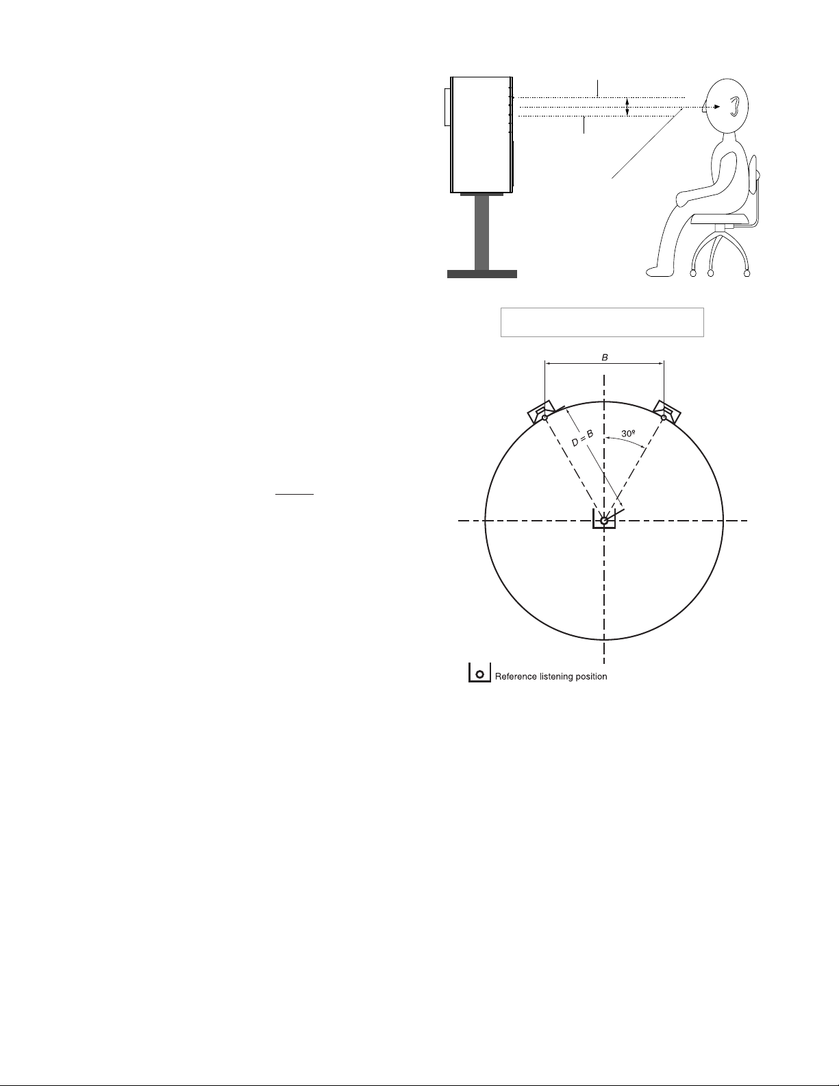
5. Next, place the SAT 12s into position. The recommended position
for the monitors is based on an ITU standard and sets the speakers
at 60 degrees from the listener, forming an equilateral triangle (a
triangle with equal sides) - See Figure 3. Fortunately, this setup
eliminates most of the math and is easily simplied to the following
guidelines: If you want to sit 2 meters from the speakers, place the
speakers 2 meters apart. If you want to sit 9 ft. from the speakers,
place the speakers 9 ft. apart Etc. Ideally the SAT 12 should be at
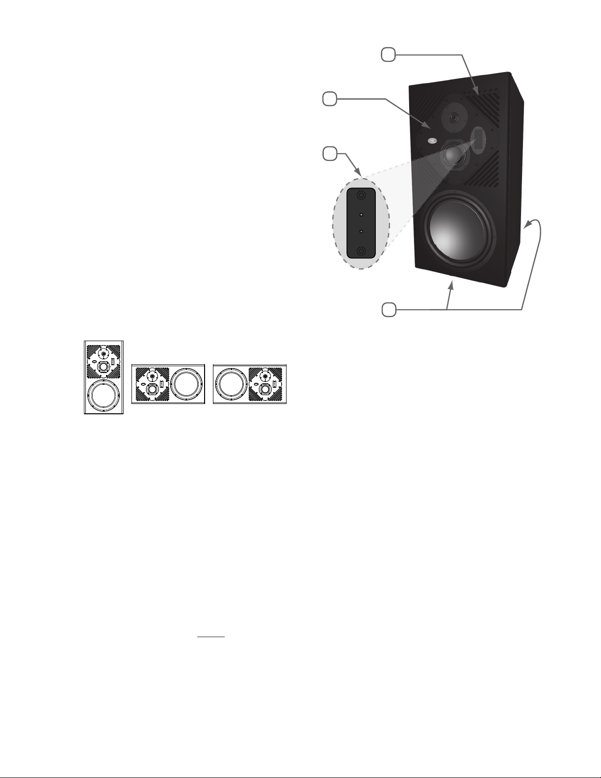
seated ear height. If this is not possible, tilting the cabinet at the
listening area can improve high-frequency coverage. For more
information about placement see page 8 [SAT 12 mounting and
placement].
6. Once all the SATs are properly placed, connect the XLR cables from
the left output on the back of the sub, to the 80Hz input on the left
SAT 12. Now do the same for the right channel, connecting the right
output to the right SAT 12. Lastly, please plug the power cords into
the IEC connectors on the SAT 12s and the subwoofer(s). Prior to
proceeding conrm that the system is wired correctly, as shown on
page 9 [System Signal Flow & Connections].
8. At this point the Blue Sky monitoring system is correctly congured,
and ready for the nal step in the installation. Prior to plugging the
system into the wall outlet, and powering up the system, do a nal
quick check of all connections and level settings.
9. If everything is correct, plug the power cords into an appropriate
outlet / circuit. Do not turn on the power switches, yet! Some
mixers and out-board equipment such as D-to-A converters and
equalizers generate loud rail-to-rail pops when they initially turn-
on. Depending on the level and the gain setting of the monitoring
system, these pops could damage the monitors. To avoid this,
always turn on equipment in the following sequence: All sources
and mixer rst, and then the monitoring system. Reverse this
procedure when shutting down your equipment.
10. At this point the Blue Sky monitoring system is fully operational, and
ready for use. Begin by playing familiar pieces of music (preferably
reference quality recordings, with dynamic and full-range sound)
which can assist you in the ne-tuning and exact positioning
of both the SATs and the active subwoofer. It is important to
remember that the positioning of the subwoofer in the room will
impact the subwoofer level. You may nd it necessary to increase
or decrease the level from the reference position. This is OK, and is
anticipated.
11. If a more exacting setup is required, using test signals and a SPL
meter, please see Page 11 [Expanded Calibration Guide].
12. Just remember - Use your ears, they are the best audio tool you
have and you will be amazed how accurate the setup can be if
you use familiar, high quality audio material during the setup of the
system.
13. Congratulations! You have now completed the setup of one of the
world’s nest monitoring systems. If you have any questions, please
do not hesitate to contact us directly with your questions: Call (516)
249-1399 (9:00am to 5:30pm EST), e-mail at support@abluesky.com
or visit the Blue Sky Forum at www.abluesky.com/forum.
Figure 3