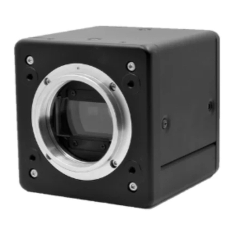
BlueVision BVC6100LM User manual

4CMOS 4K RGBIR Line scan camera
Model: BVC6100LM
Product code
Document revision v.01
BlueVision Ltd., Japan
Instruction Manual
BlueVision

BVC6100LM Instruction Manual v.01
- 2 -
Revision note

BVC6100LM Instruction Manual v.01
- 3 -
- Contents -
Revision note .......................................................................... - 2 -
Preparation before using the camera .................................................... - 5 -
Necessary equipment .......................................................................... - 5 -
2. Preparation for the shooting and basic settings of the camera ................................ - 5 -
1. Connection of equipment .................................................................. - 5 -
Installation of Camera Control Tool “3SensorTool” and initial settings of the camera ..... - 6 -
1. General ............................................................................ - 7 -
2. Specifications ..................................................................... - 7 -
3. Parts allocation and functions ...................................................... - 9 -
Parts allocation ........................................................................... - 9 -
3.2 LED indication .......................................................................... - 9 -
.......................................................... - 10 -
................................................................... - 10 -
4.2 Compatible connector/Cable Ass’y ....................................................... - 11 -
4.3 DCIN/Trigger connectorHR10A-10R-12PB(71)(Hirose) ......................................... - 12 -
4.4 Compatible connector ...................................................................... - 12 -
5. Signal Output ...................................................................... - 13 -
5.1 Camera link bit allocation .............................................................. - 13 -
5.2 Camera Link output Basic Timing chart .................................................. - 15 -
............................................................... - 15 -
.............................................................. - 16 -
......................................................................... - 17 -
............................................ - 17 -
....................................... - 17 -
....................................... - 18 -
..................................................... - 19 -
6. Camera setting ..................................................................... - 20 -
6.1 Operation mode, Sensitivity setting ....................................................... - 20 -
..................................................................... - 21 -
............................................................................. - 22 -
....................................................................... - 22 -
................................................................................. - 23 -
........................................................................... - 23 -
....................................................... - 23 -
................................................. - 23 -
.......................................................... - 25 -
6.2 SET UP for Shading, DSNU ............................................................... - 26 -
................................................................................ - 27 -
............................................................................. - 28 -
................................................................................ - 29 -
.............................................................................. - 29 -
.................................................................... - 29 -
................................................................................. - 29 -
........................................................................ - 30 -
....................................... - 31 -
6.3 LUTGAMMA setting ........................................................................ - 33 -
................................................................... - 34 -
Prepraration for Input/Output table ................................................. - 34 -
Setting by LUT curve .................................................................. - 36 -

BVC6100LM Instruction Manual v.01
- 4 -
Setting by GAMMA curve ................................................................ - 37 -
............................................................................. - 40 -
............................................................... - 40 -
..................................................................... - 40 -
.......................................................................... - 41 -
r ...................................................................... - 41 -
............................................................... - 42 -
......................................................................... - 43 -
............................................................................. - 44 -
..................................................................................... - 45 -
..................................................................................... - 46 -
.............................................................................. - 47 -
7. Serial communication ............................................................... - 48 -
........................................................... - 48 -
Command input specifications ............................................................ - 48 -
Command output specifications ............................................................ - 48 -
.......................................................................... - 49 -
8. Dimensions ......................................................................... - 55 -
9. Spectral response .................................................................. - 56 -

BVC6100LM Instruction Manual v.01
- 5 -
Preparation before using the camera
Necessary equipment
M52 mount or F mount as an option
Following lenses are available from Bluevison
20mm,24mm,28mm,35mm,50mm,105mm M mount and F mount
Camera control soft: Sample soft ”3Sensor Control Toll” is available.
This is provided by CD-ROM.
It includes 1) 3Sensor Control Tool.exe
2) BVC6100LM.ini
3) Instruction manual
Image capture board
Camera link cable: Camera side: Mini CameraLink(SDR),
Board side: Depending on used capture board
Others : PC, Monito TV、 Illumination
2. Preparation for the shooting and basic settings of the camera
1. Connection of equipment
Connect necessary equipment.
Lens (M52 mount)
Tripod base
BVA-TB01
Power
supply
12 P connector
Camera Link cable(2 cables)
Camera control Tool
3Sensor_Tool
Image capture board Software

BVC6100LM Instruction Manual v.01
- 6 -
Installation of Camera Control Tool “3SensorTool” and initial settings of the camera
2.1 Power the PC ON.
2.2 Create a new folder such as BVC6100LM.
2.3 Copy the exe file, ”3Sensor_Tool.exe” and the initial setting file, ”BVC6100.ini”
to the folder ”BVC6100LM”.
2.4 Power the camera ON and start up ”3Sensor_Tool.exe”.
※ The power is ON, and after the LED turns to “Green”, then start up the
3 Sensor Control Tool.
2.5 The following screen for Port and Baud rate settings will be displayed.
Select the com port which is set in the frame grabber board.
And set the baud rate. The default setting is 115200.
2.6 After setting, click ”OK”.
2.7 Then the following window will be opened. The default setting of the camera will be
loaded.
2.8 It is ready to capture the image. Start up the frame capture board and start to grab the
image.
Important: The camera control tool “3Sensor_Tool.exe” and its initial
setting file “BVC6100.ini” must save in the same folder such
as “BVC6100LM”.

BVC6100LM Instruction Manual v.01
- 7 -
1.General
The BVC6100LM is a four COMS line sensor(7µm and 4096 pixels) camera using a prism optics to disperse
to R,G,B and IR. The BVC6100LM has the line rate of 18030 lines per a second , rugged and compact
housing, M52 lens mount and CameraLink® Base configuration. It also employs Lens aberration
compensation circuit, Shading compensation circuit etc.
2. Specifications
Model name
Image sensor
Effective pixel: 4096 pixels
Pixel Size : 7μm × 7μm
Effective image length : 28.672 mm
CMOS, Anafocus 4K Ver.5
Pixel clock period80MHz
Total clock 4436 clk (Internal trigger)
Line rate 55.45 µs (Internal trigger)
Line frequency 18.03 KHz (Internal trigger)
Conversion efficiency
Standard illumination3500Lx, (7800K, Gain=Low, G=0, Shutter=OFF, Lens Iris=F2.8,
Line
rate=330μs, 100% output)
S/N8bit gradation (s/n: more than 48dB)
Line rate variable range
Shutter
Gain
Black level
PRNUAfter compensation: within ±2LSB (at 100% output)
DSNUAfter compensation: within ±2LSB (at 0% output)
Shading compensation
Flat shading compensation ON-OFF
Lens aberration
compensation
ON-OFF, compensation function is equipped.
Output formatFull resolution
Image output
Operation mode
(Internal/External trigger)
(Internal/External trigger)
(External trigger)
Trigger inputCamera link :LVDS (CC1)
Positive logic/ Negative logic selectable。
SynchronizationInternal / External trigger
SYNC output
Test patternColor Bar / Gradation (Horizontal)
Serial communication
interface
Camera link (SerTFG,SerTC): EIA644
Baud rate:115200bps/ 9600bps
Power supplyInput voltage

BVC6100LM Instruction Manual v.01
- 8 -
range
Current
consumption
Lens mountM52 Mount
Flange back46.5mm tolerance: 0 -0.05mm
Optical axis accuracyCenter ± 0.1mm(Max)
Operating
temperature/Humidity
- 5 ~ +45 / 20 ~80% (non-condensing
Storage
temperature/Humidity
-25 ~ +60 / 20 ~80% (Non-condensing)
Anti-vibration3G (20Hz~200Hz XYZ directions)
Anti-shock50G
RegulationCISPR32/EN55032 Class A
Outlook dimensions (excluding protrusion and lens mount)
Weight
Connector・LED
・Mini Camera link (SDR)
Function:Image output/Communication/External trigger
・Hirose 12Pin
Function: Power input/ External trigger/ EEN
・Rear Panel LED
Function:Indications for power input, operation and trigger input
OtherField upgrade function

BVC6100LM Instruction Manual v.01
- 9 -
3. Parts allocation and functions
Parts allocation
Lens mount: Use M52 mount Lens
The following are available by BlueVision
Input DC 12V to 24V
(Refer to sections 4.3 and 4.4 for the pin assignment)
Camera Link connector: Mini camera link connector for image output and trigger input
(Refer to sections 4.1 and 4.2 for the details)
Holes for camera There are the set of four holes on the front, top and bottom for
setting screws fixing screws of camera. It is M4 6mm depth. Four holes on the
top/bottom will be used for optional tripod base, BVA-TB01.
3.2 LED indication
Orange lighting: Initialize the camera
Green lighting: In operation
✹ Green flashing: Receiving an external trigger
Top
Front
Bottom
Rear

BVC6100LM Instruction Manual v.01
- 10 -
Camera Link 1
Camera connector Cable Name Cannel Link Signal Camera Signal
Pair polarity - Pair polarity +
1 Inner Shield Inner Shield GND
14 Inner Shield Inner Shield GND
2 15 Pair 1 X0 out Data
3 16 Pair 2 X1 out Data
4 17 Pair 3 X2 out Data
5 18 Pair 4 Xclk Clock
6 19 Pair 5 X3 out Data
7 20 Pair 6 SerTC Uart RXD
8 21 Pair 7 SerTFG Uart TXD
9 22 Pair 8 CC1 Trigger
10 23 Pair 9 CC2 NC
11 24 Pair 10 CC3 NC
12 25 Pair 11 CC4 NC
13 Inner Shield Inner Shield GND
26 Inner Shield Inner Shield GND
Note: As for the bit allocation for TxOUT0 to 3, refer to section 5.1 Camera link bit allocation.
Camera Link 2
Camera connector Cable Name Cannel Link Signal Camera Signal
Pair polarity - Pair polarity +
1 Inner Shield Inner Shield GND
14 Inner Shield Inner Shield GND
2 15 Pair 1 Y0 out Data
3 16 Pair 2 Y1 out Data
4 17 Pair 3 Y2 out Data
5 18 Pair 4 Yclk Clock
6 19 Pair 5 Y3 out Data
7 20 Pair 6 100Ω Terminated
8 21 Pair 7 - NC
9 22 Pair 8 - NC
10 23 Pair 9 - NC
11 24 Pair 10 - NC
12 25 Pair 11 - NC
13 Inner Shield Inner Shield GND
26 Inner Shield Inner Shield GND

BVC6100LM Instruction Manual v.01
- 11 -
4.2 Compatible connector/Cable Ass’y
No.ManufactureTypeNote
Camera side3M12226-1100-00PL
Cable Ass’yHIRAKAWA
HEWTECH CORP.
10m
Note 1.The applicable cable length of the mentioned cable assembly is from 1m to 10m.
Note 2.If the cable is not compliant with CameraLink specifications, the cable length to
communicate is restricted.
CAUTION:
In case that the frame grabber board to be used with the camera employs a mini camera link connector,
it is needed to pay attention about the direction of the connector.
The side of the connector to indicate “CAMERA” should be connected to the camera. Refer to a picture
shown below. If the direction of the connector is reversed, the bit error noise might be appeared on
the picture.
Also
In case of DAUL for Base Configuration, it may not connect physically due to the position of connector at frame grabber
board side.
To camera

BVC6100LM Instruction Manual v.01
- 12 -
4.3 DCIN/Trigger connectorHR10A-10R-12PB(71)(Hirose)
No. Signal name I/O Note
1 GND GND
2 DC in DC10.8V~26.4V
3 GND GND
4 NC N.C.
5 NC N.C.
6 NC N.C.
7 NC N.C.
8 GPI I Trigger
9 GPO O EEN
10 NC N.C.
11 DC in DC10.8V~26.4V
12 GND GND
※ EEN (Exposure Enable) signal is used for the trigger of external light.
It is +12V, Open Collector.
4.4 Compatible connector
No.
Maker
Model
N
ote
C
amera side
HIROSE
HR10A
-
10R
-
12PB(71)
C
able side
HIROSE
HR10A
-
10P
-
12S
p
lug

BVC6100LM Instruction Manual v.01
- 13 -
5. Signal Output
5.1 Camera link bit allocation
Port/Bit 8-bit x 4
Output
10-bit x 4
Output
12-bit x 4
Output
Camera Link
No
PinName
Port A0 R[4] R[2] R[0] 1 TX0
Port A1 R[5] R[3] R[1] 1 TX1
Port A2 R[6] R[4] R[2] 1 TX2
Port A3 R[7] R[5] R[3] 1 TX3
Port A4 R[8] R[6] R[4] 1 TX4
Port A5 R[9] R[7] R[5] 1 TX6
Port A6 R[10] R[8] R[6] 1 TX27
Port A7 R[11] R[9] R[7] 1 TX5
Port B0 G[4] R[10] R[8] 1 TX7
Port B1 G[5] R[11] R[9] 1 TX8
Port B2 G[6] - R[10] 1 TX9
Port B3 G[7] - R[11] 1 TX12
Port B4 G[8] B[10] B[8] 1 TX13
Port B5 G[9] B[11] B[9] 1 TX14
Port B6 G[10] - B[10] 1 TX10
Port B7 G[11] - B[11] 1 TX11
Port C0 B[4] B[2] B[0] 1 TX15
Port C1 B[5] B[3] B[1] 1 TX18
Port C2 B[6] B[4] B[2] 1 TX19
Port C3 B[7] B[5] B[3] 1 TX20
Port C4 B[8] B[6] B[4] 1 TX21
Port C5 B[9] B[7] B[5] 1 TX22
Port C6 B[10] B[8] B[6] 1 TX16
Port C7 B[11] B[9] B[7] 1 TX17
Port D0 IR[4] IR[2] IR[0] 2 TX0
Port D1 IR[5] IR[3] IR[1] 2 TX1
Port D2 IR[6] IR[4] IR[2] 2 TX2
Port D3 IR[7] IR[5] IR[3] 2 TX3
Port D4 IR[8] IR[6] IR[4] 2 TX4
Port D5 IR[9] IR[7] IR[5] 2 TX6
Port D6 IR[10] IR[8] IR[6] 2 TX27
Port D7 IR[11] IR[9] IR[7] 2 TX5
Port E0 - G[2] G[0] 2 TX7
Port E1 - G[3] G[1] 2 TX8
Port E2 - G[4] G[2] 2 TX9
Port E3 - G[5] G[3] 2 TX12
Port E4 - G[6] G[4] 2 TX13
Port E5 - G[7] G[5] 2 TX14
Port E6 - G[8] G[6] 2 TX10
Port E7 - G[9] G[7] 2 TX11
Port F0 - G[10] G[8] 2 TX15
Port F1 - G[11] G[9] 2 TX18
Port F2 - - G[10] 2 TX19
Port F3 - - G[11] 2 TX20
Port F4 - IR[10] IR[8] 2 TX21
Port F5 - IR[11] IR[9] 2 TX22
Port F6 - - IR[10] 2 TX16
Port F7 - - IR[11] 2 TX17
- LVAL LVAL LVAL 1,2 TX24
- DVAL DVAL DVAL 1,2 TX26
TX23,TX25 are GND.

BVC6100LM Instruction Manual v.01
- 14 -
(Output timing)
TxCLK
TxOUT3 A7 A6 EEN C7 C6 B7 B6 A7 A6
TxOUT2 C3 C2 LVAL DVAL C5 C4 C3 C2
TxOUT1 B2 B1 C1 C0 B5 B4 B3 B2 B1
TxOUT0 A1 A0 B0 A5 A4 A3 A2 A! A0
1 Pixel cycle

BVC6100LM Instruction Manual v.01
- 15 -
5.2 Camera Link output Basic Timing chart
5.2.1 OB output mode “ON”
③
②
Optical Black Optical Black
Active Pixel ①
Note 1
16 Pixel 16 Pixel

BVC6100LM Instruction Manual v.01
- 16 -
5.2.2 OB output mode “OFF”
② Pixel
Optica Black
16PIXEL
Optical Black
1
6PIXEL
Active Pixel ①
Note 1

BVC6100LM Instruction Manual v.01
- 17 -
5.3 Exporsure control
5.3.1 Trigger mode OFFNO_SHUTTER_MODE
L i n e R a t e
Exposure period
R,G,B,IR
Video data
R,G,B,IR
5.3.2 Trigger mode OFFSHUTTER_SELECT_MODE
Exposure start
Exposure start
Exposure start
Exposure start
Exposure period
Video data
Exposure period
Video data
Exposure period
Video data
Exposure period
Video data
<R>
<G>
<B>
<IR>
L i n e R a t e

BVC6100LM Instruction Manual v.01
- 18 -
5.3.3 Trigger modeONSHUTTER_SELECT_MODE
Exposure start
Exposure start
Exposure start
Exposure start
Exposure period
Video data
Exposure period
Video data
Exposure period
Video data
Exposure period
Video data
<R>
<G>
<B>
<IR>
External Trigger
(CC1 or DCIN Trigger)
E x t e r n a l t r i g g e r c y c l e
E x t e r n a l t r i g g e r c y c l e

BVC6100LM Instruction Manual v.01
- 19 -
5.3.4 Trigger mode ONTriggerWidth
Exposure period
R,G,B,IR
Video data
R,G,B,IR
External Trigger
(CC1 or DCIN Trigger) E x t e r n a l t r i g g e r c yc l e
E x t e rn al t r i g g e r c y c l e
Exposure start

BVC6100LM Instruction Manual v.01
- 20 -
6. Camera setting
6.1 Operation mode, Sensitivity setting
Line rate
Exposure
time
Gain
Black
level
White balance
Exposure
time Pulse
output
Operation
mode
Data save
and Readout
This manual suits for next models
1
Table of contents
Other BlueVision Digital Camera manuals
Popular Digital Camera manuals by other brands
SENS8
SENS8 Light Cam user guide

DeepSea Power & Light
DeepSea Power & Light Super Wide-i SeaCam Operator's manual
Sony
Sony Cyber-shot DSC-H2 user's guide / troubleshooting
Sony
Sony DSC-W350 Cyber-shot® instruction manual
Panasonic
Panasonic LUMIX DMC-GX80 Operating instruction
JAI
JAI GOX-6409M-PGE user manual
