BM PRO TrailSafe User manual

TEAMBMPRO.COM
OWNER’S MANUAL
TrailSafe


TEAM
BMPRO
.COM
POWERING YOUR ADVENTURES
With over 50 years’ experience in power
solutions combined with manufacturing
and design facilities in Melbourne,
Australia, BMPRO are the leading
experts in RV power management.
Inspired by the great outdoors, we
have created a range of rugged, smart
and reliable products to power your
adventures.
Our range of battery, power and RV
management and control systems gives
you peace of mind when you are on the
road, so that you can relax in even the
most far-flung destinations, knowing
you have control over your power
needs.
To learn more about the BMPRO range
of products, please visit our website
teambmpro.com
SAFETY PRECAUTIONS
WARNING
Correct installation is the most critical factor in ensuring the safe use of the TrailSafe
If every consideration of these instructions has been satisfied, the TrailSafe will be
safe to operate.
Before wiring / servicing TrailSafe, disconnect it from all power sources.
The pull pin should be tested before use to confirm the effectiveness of contacts,
particularly if exposed to salt water.
The TrailSafe is a high precision electronic product. It contains no user-serviceable
parts inside. Do not try to dismantle, modify or repair it yourself. Disassembly,
service or repair by an unauthorised person will void the warranty.
It is essential the house battery is well maintained and must have at least 50% of
nominal capacity available.
It is essential all wiring is protected by fusing close to any power source.
Please read the Safety Precautions before installing or using the TrailSafe series.
Be sure to observe all precautions without fail. Failure to observe these instructions
properly may result in property damage or personal injury which, depending on the
circumstances, may be serious and cause loss of life.
After completing installation of the TrailSafe, conduct a trial operation to check for
faults. Please refer to INITIAL SELF TEST FOR TRAILSAFE section to check for faults.
4

CONTENTS
SAFETY PRECAUTIONS 4
ABOUT THE TRAILSAFE 6
Key Features 6
What’s Included 6
INSTALLATION INSTRUCTIONS 7
WIRING INSTRUCTIONS 8
Initial Self Test For TrailSafe 10
IN-CAR MONITORING 10
LED STATUS INDICATORS 11
SERVICING 12
FAQS + TROUBLESHOOTING 12
SPECIFICATIONS 13
WARRANTY TERMS AND CONDITIONS 14
Copyright © 2020
MANUAL PART 034923
REV 1.0
Designed by BMPRO, one of Australia’s leading power solution experts, the BMPRO range of
products are proudly Australian-Made in Melbourne, Victoria and represent a high-quality
product that will provide years of service.
DISCLAIMER: BMPRO accepts no liability for any loss or damage which may occur from
the improper or unsafe use of its products. Warranty is only valid if the unit has not been
modified or misused by the customer.
5

VEHICLE STANDARDS
Australian Design Rule 38/05 mandates that for all trailers having a Gross Trailer
Mass over 2,000 kg, an emergency braking system is required on all wheels and must
be capable of automatically activating should the trailer become detached from the
tow vehicle. In such a situation the brakes must remain active for a minimum of 15
minutes.
TRAILSAFE
TrailSafe is a system designed to activate the electric brakes of a trailer, caravan (or
similar) in the event of a disconnection from the towing vehicle. It utilises the house
battery located on the trailer to activate the electric brake system and brake lights on
the trailer in the emergency breakaway situation.
TrailSafe also provides an indication of the charge status of the house battery and
checks the condition of the Pull Pin and effective activation of the brakes. This
information is displayed via a multi coloured LED on the TrailSafe unit and also on the
Bluetooth TrailCheck available for in-car monitoring if installed.
Mechanical Pull Pin is forcibly detached when the towing vehicle becomes separated
from the trailer to detect the disconnection. Upon disconnection, the brakes and
brake lights are activated as long as charge remains in the trailer battery or until the
pin is replaced.
KEY FEATURES
9Bluetooth and wired connectivity options for in-vehicle monitors
9Intelligent time-out to protect brakes
9Works off house battery – no additional battery required
9LED status indicators for full system safety check at trailer tongue
9Meets Australian regulations for break away systems on trailers over 2000kgs.
9Tests pull pin functionality as well as battery health
9Activates brake lights as well as electric brakes in the event of a break away
WHAT’S INCLUDED
Included with this product are:
9TrailSafe
9TrailSafe Owner’s Manual
9Mounting Screw
ABOUT TRAILSAFE
6

INSTALLATION INSTRUCTIONS
MOUNTING LOCATION
Secure TrailSafe to the right hand side draw bar of the trailer (the driver’s side)
approximately 300mm from the tow ball hitch. Mount horizontally on top or side of
the draw bar.
MOUNTING METHOD
Mount on the arm of the trailer using the supplied mounting screw or similar. Only
one mounting point is required so that the unit can swivel in an emergency. Ensure
that it is secured tightly so that it does not vibrate loose.
MOUNTING ORIENTATION
The wires and mounting bolt should be pointing towards the rear i.e. away from the
tow vehicle so that the pull pin is facing towards the tow vehicle. The pull pin will
then be pulled out freely should the vehicle and trailer separate. The other end of the
pull pin cord is attached to the towing vehicle by a D-shackle or similar.
7

NOTE: Larger wire sizes maybe used. Minimum shown.
Red/Black: 30A automotive-grade fuse must be located as close to the trailer
battery as possible, but not before the battery charging source feed.
Wire the TrailSafe to the house battery, trailer brakes and brake lights according
to Figure 1, the TrailSafe Wiring Diagram.
WIRING INSTRUCTIONS FOR TRAILSAFE
The TrailSafe has multiple colored wires coming from the rear side which require
connection to ensure correct functionality. As this is a safety critical system all
wiring should be done by a suitably qualified Auto Electrician.
TRAILSAFE
RED (14AWG / 2.5mm2) to the positive of the brake lights
BLUE (12 AWG/ 4 mm2) to the positive of the brakes
PURPLE (14 AWG/ 2.5 mm2) to the remote line
WHITE (14 AWG/ 2.5 mm2) to the negative of the house battery
BLACK/RED (12AWG / 4mm2 ) to the positive of the house battery (30A Fuse Required)
RED (14AWG / 2.5mm2) to the positive of the brake lights
GREEN (20AWG / 0.5mm2)
To positive terminal of house battery if using LiFePO4
Unconnected or negative terminal of house battery if
using Lead Acid
WARNING
User must connect Green wire to battery positive terminal when LiFePO4
battery is used. Failure to do so may result in false battery capacity information.
Failure to install the fuse may result in permanent and
serious failure or damage to the TrailSafe and / or the wiring.
WARNING
8
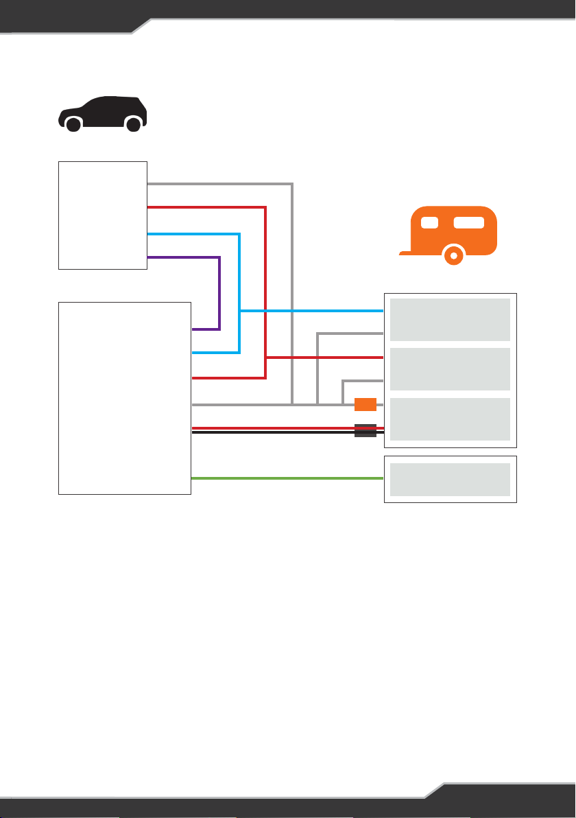
Figure 1 TrailSafe Wiring Diagram
NOTES: The return (negative) wires of brakes & brake lights from trailer must be
wired directly to:
9One of the negative output connections on BatteryPlus35 or J35 if fitted
9To the non-battery side of a negative side shunt such as the BC300
9Directly to the battery negative in all other cases
Ensure the house battery has a suitable charging source such as a BatteryPlus35,
J35 or other charging means and is functioning correctly. Refer to manufacturer’s
instructions for these products as required. A basic charging means such as diode
from the Auxiliary to the house battery may be employed in simple systems.
An external automotive-grade fuse is required to be fitted (30 A maximum) between
the TrailSafe and the battery to protect against wiring faults and issues.
Tow Vehicle
0V
Brake Light
Brake
Monitor
Blue
Purple Brakes
+
–
Brake Lights
30A Fuse
+
–
House Battery
Chemistry
Selection
–
+
TrailSafe Trailer
Red
White
Red / Black
Green
BatteryPlus35/J35
9

INITIAL SELF TEST FOR TRAILSAFE
1. Before starting, ensure TrailSafe Pull Pin is in place.
2. Power up TrailSafe from 12V battery as per wiring instructions. Then the LED
will display Continuous Flashing PURPLE, indicating 1st stage of calibration is in
progress for up to 5 minutes.
3. When 1st stage is completed, the LED will display Solid PURPLE. User is required
to pull the safety pin out. Then the LED will display Continuous Flashing PURPLE
again, indicating 2nd stage of calibration is ongoing for up to 1 minute.
4. Upon completion, LED will display Solid PURPLE again. At this stage, put pull pin
back in. Then one of the Status Indicators will light up. See Indicator section for
details.
IN-CAR MONITOR
If in-car monitor is used, it should be located so that it is visible to the driver.
Refer to the Wireless monitor TrailCheck manual for more details.
10

TrailSafe in calibration 1. Wait until LED goes solid PURPLE.
2. If occurring after removing pull-pin, wait until
indicator changes then put pull-pin back in.
Completed 1st or 2nd
calibration stage
If pin is in when Solid PURPLE, remove pin;
if pin is out when Solid PURPLE, put pin back in.
Pull-pin removed before
calibration stage completed
Put pull pin back in to restart.
House battery capacity sufficient for 15mins of emergency braking operation
TrailSafe standby or no power If necessary, check TrailSafe by depressing
brake.
House battery may have
insufficient capacity for 15mins
emergency braking operation
Check battery to ensure at least 10Ah house
battery capacity available.
TrailSafe in standby and battery
may have insufficient capacity
for 15mins emergency braking
operation
Check battery to ensure over 10Ah house
battery capacity available.
TrailSafe breakaway switch
faulty or corroded
Do not use unit. Replace unit.
Pin out or trailer breakaway
House battery not detected or
insufficient capacity for 15mins
of emergency braking operation
Charge or replace house battery.
TrailSafe in standby and house
battery insufficient for 15mins
of operation
Charge or replace house battery.
Pull pin out when
calibration starts
Put pull pin back in; wait for 1 minute
or power cycle unit to restart calibration.
CONDITIONSTATUS SOLUTION
LED STATUS INDICATORS
FLASH ONCE
SOLID COLOURCONTINUOUS FLASH
NO LIGHT
KEY LED STATUS
11

FAQS AND TROUBLESHOOTING
Need more help troubleshooting your TrailSafe?
Contact our customer service team online at teambmpro.com/technical-support/
or give us a call on (03) 9763 0962.
When I pull the pin, TrailSafe indicator does not illuminate?
1. Check the supplied fuse on the Black/Red wire
2. Check the wiring matches the diagram
3. Ensure TrailSafe pin slot is clean of dirt
4. Ensure House Battery is charged.
Why should I test TrailSafe before hitching to the tow vehicle?
Testing TrailSafe ensures that the house battery has sufficient capacity
to operate the brakes for at least 15 minutes should the need arise.
What is the difference between a solid green, orange and red Status Indications
on the TrailSafe?
GREEN confirms that the battery has been detected, has been determined to
have sufficient charge and no fault in the wiring to the brakes has been detected.
Good to go!
ORANGE indicates the need for a secondary check, the battery maybe too low.
RED indicates that battery is not detected or doesn’t have enough capacity
for 15mins emergency brake operation.
It is possible that with dual axles brakes, heavy brake light loads, warm batteries,
a large load on the trailer etc, that the battery is sufficient but failing to give a clear
pass.
It is necessary that there is at least 10Ah of useful battery capacity remaining, which
may require 20% of aged 100Ah-rated battery for this load. If any loads
(e.g. lights, 12V fridges) are on in the trailer, turn these off if possible. If your trailer
or caravan has a display showing remaining battery capacity this should be able to
provide a useful indication that there is enough battery capacity remaining for the
emergency braking function.
SERVICING
Do not attempt to service the TrailSafe series products yourself or dismantle, modify
or repair the TrailSafe series products yourself; this will void your warranty. If your
TrailSafe product requires servicing, please consult your BMPRO dealer or visit
teambmpro.com for assistance.
12

Can I use a wired in-car monitor?
A wired 12VDC battery voltage indicator can be used with TrailSafe series if desired.
When I pull the pin, the LED displays flashing RED -ORANGE?
The pull pin internal contacts may have become corroded particularly by exposure to
salt water or dirt leading to the resistance building up which may cause the brakes to
not operate correctly or for as long as desired.
I have charged my house battery, but TrailSafe shows an RED LED.
If a large load is applied to the house battery, such as a fridge, the house battery
terminal voltage may drop below the minimum TrailSafe threshold (due to the
internal resistance of the house battery).
Switch off any loads and re-test.
I thought it was not a good idea to remove the pin?
This is a key feature of the device and by removing the pin to test the unit it checks
to ensure that the contacts inside the case are not corroded and capable of making
a suitable electrical connection including wiring to the brakes. It also checks the
battery is ready to function should an emergency happen.
SPECIFICATIONS
TRAILSAFE SPECIFICATIONS
System Voltage 12V Nominal (not suitable for 24V systems)
Electric Brake Load 18A max
Brake Light Load 8A max
Communications Bluetooth Low Energy (BLE 5.0)
Wired Monitor Current 30mA max
Battery Chemistry Compatibility LiFePO4/Lead Acid
Temperature -20°C to 60°C
IP rating IP67
Battery Nominal Capacity 70Ah – 300Ah
13

WARRANTY TERMS AND CONDITIONS
Registering your BMPRO product is an important step to ensure that you receive all
the benefits you are entitled to. Please visit teambmpro.com to complete the online
registration form for your new product today.
1. BMPRO goods come with guarantees that cannot be excluded under Australian
Consumer Law. You are entitled to a replacement or refund for major failure and for
compensation for any reasonably foreseeable loss or damage. You are entitled to
have the goods repaired or replaced if the goods fail to be of acceptable quality and
the failure does not amount to a major failure. The benefits under this Warranty are
in addition to your other rights and remedies under a law in relation to the goods to
which this Warranty relates (the Australian Consumer Law).
2. BMPRO warrants products against defects for a period of two years, commencing
from the original date of purchase. Proof of purchase is required before you can
make a claim under this warranty.
HOW TO PROTECT YOUR RIGHTS UNDER THIS WARRANTY
3. The TrailCheck is designed to be installed by a suitably qualified installer. You or
your installer should carefully inspect the products before installation for any visible
manufacturing defects. We accept no responsibility in addition to our consumer
guarantee obligations where a product has been installed incorrectly.
4. This warranty does not extend to product failures or defects caused by, or
associated with, but not limited to: failure to install or maintain correctly,
unsuitable physical or operating environment, accident, acts of God, hazard,
misuse, unauthorised repair, modification or alteration, natural disaster, corrosive
environment, insect or vermin infestation and failure to comply with any additional
instructions supplied with the product.
5. BMPRO may seek reimbursement of any costs incurred by BMPRO when a product
is found to be in proper working order or damaged as a result of any of the warranty
exclusions mentioned in point 4 of this statement.
6. To enquire or make a claim under this warranty, please follow these steps:
a. Prior to returning a BMPRO product, please email serv[email protected]
to obtain a Return Material Authorisation (RMA) number
b. Package and send the product to:
BMPRO Warranty Department
19 Henderson Road
Knoxfield, VIC 3180
Please mark RMA details on the outside of the packaging
c. Please ensure the package also includes: a copy of the proof of purchase,
a detailed description of the fault and your contact details including phone
number and return address.
7. BMPRO will not be liable for any costs, charges or expenses incurred in the process
of returning a product in order to initiate a warranty claim.
14

15

TEAM
BMPRO
.COM
POWERING YOUR ADVENTURES.
BMPRO
+61 3 9763 0962 |sales@teambmpro.com
19 Henderson Rd, Knoxfield VIC 3180 Australia
teambmpro.com
Table of contents
Other BM PRO Caravan manuals


