manuals.online logo
Brands
  1. Home
  2. •
  3. Brands
  4. •
  5. BM PRO
  6. •
  7. Server
  8. •
  9. BM PRO BC300 XTERNAL SHUNT User manual

BM PRO BC300 XTERNAL SHUNT User manual

BC300 + CommLink Install Guide
TEAM
BMPRO
.COM
2. CommLink Connection Points
1. Parts
3. Wiring Diagram
If another BMPRO product also
needs the CAN port on the
BatteryPlus35/J35/ASPower,
both the other product and the
CommLink can be daisy-chained
by connecting to any other spare
CAN ports.
4. Connecting the BC300 and CommLink
The BMPRO BC300 External Shunt and CommLink provides additional battery monitoring for your BatteryPlus35 and J35
battery management systems, connecting directly to battery via the BC300 External Shunt. This enhances system behaviour
with temperature monitoring of the battery for greater protection.
The addition of the BC300 to the BatteryPlus35 and J35 battery management systems allows monitoring high current loads
and external charge sources.
1. Negative Battery Connection
2. New Negative Terminal Connection
3. ‘+’ Positive Flying Lead and
Temperature Sensor
4. LED Status Indicator
The CommLink connects to the
BatteryPlus35/J35/ASPower via a CAN
Cable.
1. Disconnect and remove all connections to the battery.
2. Using the CommLink data cable, connect the CommLink to the
BatteryPlus35/J35/ASPower CAN bus.
3. Connect the negative battery connection to the battery negative
terminal using the provided connector or directly to the battery.
4. Ensure the correct terminal on both the battery and the BC300 is used.
5. Connect all negative load connections to the new negative terminal
connection on the BC300.
6. Connect all positive load connections including the BC300’s positive
flying lead to the battery positive terminal.
5. CAN Bus sockets
6. Recessed Status Indicator
7. Recessed Pair Button
ALL NEGATIVES
CAN CABLE
BATTERY
MONITORS
Trek
RVView2
BATTERY MANAGEMENT
SYSTEMS
BP35-II
J35
ASPERO
NODES
OdysseyLink
ControlNode
TO BATTERY
MANAGEMENT
SYSTEMS
DOC PART 038631
REV 1.0
5. Parallel Battery Installation
7. Troubleshooting
6. Pairing the CommLink with the BC300
TEAM
BMPRO
.COM
8. BC300 LED Status Indicator
PRODUCT PAGE MANUAL DATASHEET
9. CommLink LED Satus Indicator
When connecting to a parallel battery installation, the
earth strap linking the batteries must remain on the
battery terminals and must be located on the negative
battery connection side of the BC300.
When the BC300 is connected to the battery it will enter pairing
mode for two minutes, shown with a flashing blue LED. It must be
paired to the CommLink during this time.
With a pen or similar, press the CommLink pair button.
The CommLink status indicator will flash blue. It may take up to one
minute for pairing to complete.
CommLink flashes red
If the CommLink flashes red, it is not receiving data.
1. Hold down the CommLink pair button with a pen or similar
until the status indicator changes from red to orange.
This should take 5 seconds.
2. Pair the CommLink with the BC300 again.
CommLink not pairing to BC300
If the CommLink flashes orange, it has not paired to the BC300.
1. Disconnect and reconnecr the BC300’s positive flying lead from
the battery positive terminal.
2. Repeat the pairing process. If there are continued failures,
install the CommLink closer to the BC300 or identify possible
interference sources.
LED COLOUR STATUS
NOT PAIRED
PAIRING
NORMAL OPERATION
NOT RECIEVING DATA FROM THE BC300
LED COLOUR STATUS
AVAILABLE FOR PAIRING
NORMAL OPERATION
One or more battery fault conditions detected:
i. Battery voltage outside 8V-16C range
ii. Battery current exceeding 300A
iii. Battery temperature outside -20C to 70C range
iv. BC300 external shunt temperature outside operating limits
DOC PART 038631
REV 1.0
Other manuals for BC300 XTERNAL SHUNT

1

Other BM PRO Server manuals

BM PRO J35 User manual

BM PRO

BM PRO J35 User manual

BM PRO J35 User manual

BM PRO

BM PRO J35 User manual

Popular Server manuals by other brands

DW Blackjack P-Rack-LX DW-BJP1U-LX quick start guide

DW

DW Blackjack P-Rack-LX DW-BJP1U-LX quick start guide

Extreme Networks ExtremeSwitching Virtual Services Platform 8000... installation guide

Extreme Networks

Extreme Networks ExtremeSwitching Virtual Services Platform 8000... installation guide

Axis StorPoint NAS 100 user manual

Axis

Axis StorPoint NAS 100 user manual

Buffalo HD-H0.6TGL Quick setup guide

Buffalo

Buffalo HD-H0.6TGL Quick setup guide

Lenovo ThinkServer TD200x Installations- und Benutzerhandbuch

Lenovo

Lenovo ThinkServer TD200x Installations- und Benutzerhandbuch

Toshiba STRATA CIX Technical bulletin

Toshiba

Toshiba STRATA CIX Technical bulletin

NEC NEC Express5800 Series Configuration guide

NEC

NEC NEC Express5800 Series Configuration guide

Lenovo ThinkSERVER TS130 warranty and support information

Lenovo

Lenovo ThinkSERVER TS130 warranty and support information

HP BL870c i2 Integrity Specifications

HP

HP BL870c i2 Integrity Specifications

Axis 282 Specifications

Axis

Axis 282 Specifications

HP CL2100 G3 807S User and maintenance guide

HP

HP CL2100 G3 807S User and maintenance guide

Supermicro SuperServer SYS-621BT-HNTR user manual

Supermicro

Supermicro SuperServer SYS-621BT-HNTR user manual

AXIOMTEK NA-821 Series user manual

AXIOMTEK

AXIOMTEK NA-821 Series user manual

Logicbus PDS Series quick start guide

Logicbus

Logicbus PDS Series quick start guide

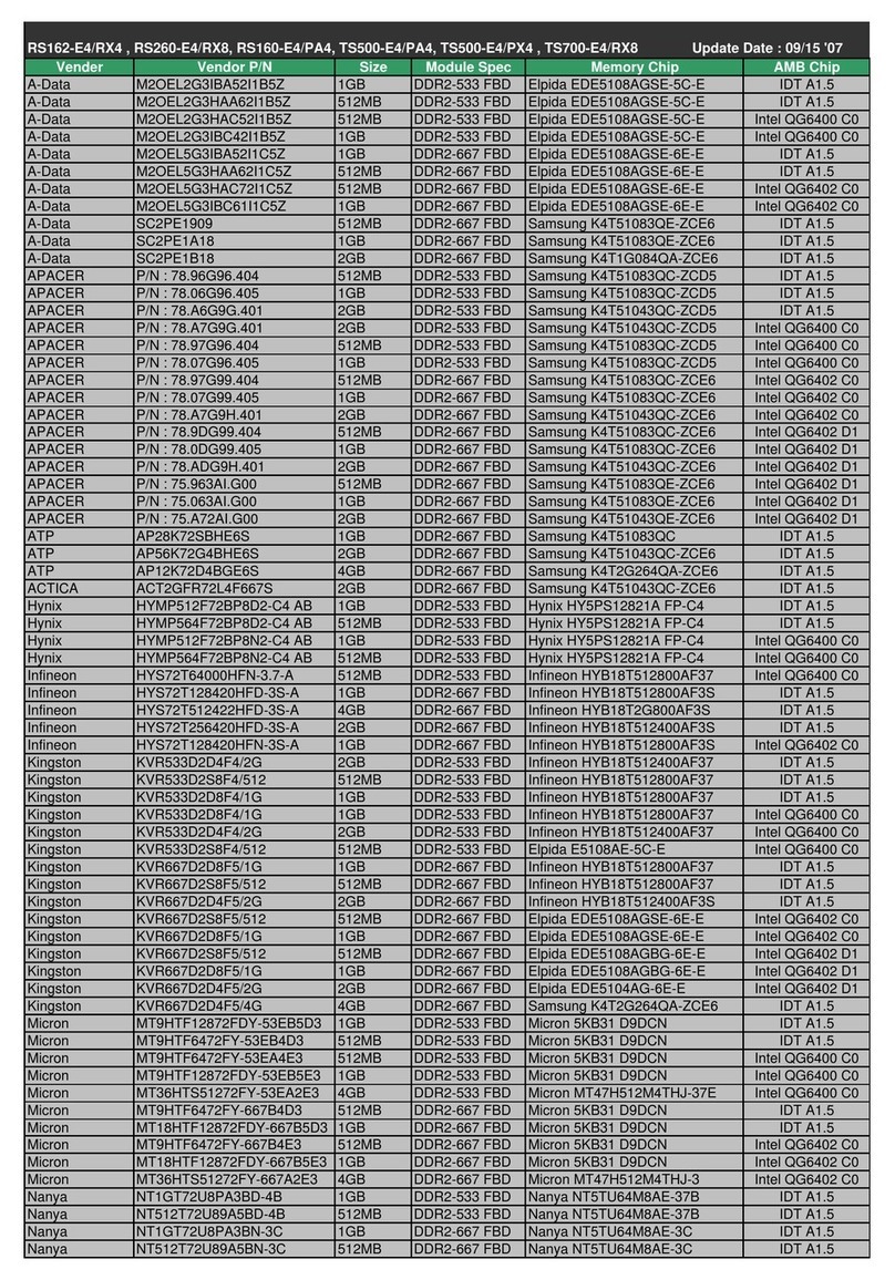
Asus RS162-E4 RX4 datasheet

Asus

Asus RS162-E4 RX4 datasheet

Dell PowerEdge PDU Managed LED manual

Dell

Dell PowerEdge PDU Managed LED manual

Red Hat SATELLITE 5.3.0 RELEASE NOTES release note

Red Hat

Red Hat SATELLITE 5.3.0 RELEASE NOTES release note

W&T 53641 manual

W&T

W&T 53641 manual

manuals.online logo
manuals.online logoBrands
  • About & Mission
  • Contact us
  • Privacy Policy
  • Terms and Conditions

Copyright 2025 Manuals.Online. All Rights Reserved.