BMC GW024 User manual

Page 1 of 48
NOTE: Models covered by this installation manual are NOT for use as
pool heaters or in marine applications.
MIS-3159
Earth Loop Fluid Temperatures 25° – 110°F
Ground Water Temperatures 45° – 75°
Manual: 2100-583G
Supersedes: 2100-583F
Date: 5-17-18
BMC, Inc.
Bryan, Ohio 43506
INSTALLATION INSTRUCTIONS
WATER-TO-WATER
GEOTHERMAL HEAT PUMP
Models:
GW024 GW036 GW048 GW060 GW070

Manual 2100-583G
Page 2 of 48
CONTENTS
Getting Other Informations and Publications......... 3
General Information
Water Source Nomenclature..................................... 4
Application and Location
General ................................................................. 7
Shipping Damage ..................................................... 7
Application ................................................................ 7
Location ................................................................. 7
Unit Stacking............................................................. 7
Additional Consideration ........................................... 7
Required Steps after Final Placement ...................... 7
ANSI Z535.5 Denitions............................................ 8
Power & Control Wiring
High Voltage Line Supply.......................................... 9
Low Voltage Control Wires........................................ 9
Control Wiring ......................................................... 11
Relocatable Control Panel...................................... 10
Wiring - Low Voltage
Dual Primary & Low Voltage Connections
............ 12
P
iping Access to Unit
Loop, Load & Desuperheater Connections............. 13
Load Side
Water Connections
Sizing Buffer Tanks for Zoned Systems .................. 14
Ground Loop (Earth
Coupled Water Loop App.)
Circulation System Design...................................... 16
Ground Water (
Well System App.)
Water Connections.................................................. 18
Well Pump Sizing............................................18 & 19
System Start Up Procedure for Ground Water App. ...
20
Water Corrosion...................................................... 20
Remedies of Water Problems ................................. 21
Lake & Pond Installations ....................................... 22
Desuperheater (Potable Hot Water Assist)
Description .............................................................. 23
Location ............................................................... 23
Electrical Connection .............................................. 23
Installation Procedure - General ............................. 23
Operation of Heat Recovery Unit ............................ 24
Start Up & Check Out ............................................. 24
Maintenance ........................................................... 24
Control Board Sequence of Operation.................... 28
Sequence of Operation
Part Load Cooling ................................................... 29
Full Load Cooling .................................................... 29
Part Load Heating ................................................... 29
Full Load Heating.................................................... 29
Geothermal Logic Control ....................................... 29
High & Low Pressure Switch................................... 30
Flow Switch............................................................. 30
Over/Under Voltage Protection ............................... 30
Intelligent Reset ...................................................... 30
Alarm Output........................................................... 30
Pressure Service Ports ........................................... 30
Checking Refrigerant Quantity................................ 30
Refrigerant Charge
General ............................................................... 31
R-410A & Topping Off System Charge ................... 31
Safety Practices ...................................................... 31
Troubleshooting
Table ............................................................... 45
Service
Hints, Unbrazing System Components & Compressor
Solenoid ............................................................... 46
Ground Source HP Perf. Report
& Checklist - Perform. Unit............................ 47 & 48
Figures
Figure 1 Unit Dimensions ....................................... 6
Figure 2 Wire Routing to Control Panel.................. 9
Figure 3 Changing Water Entrance Location ....... 10
Figure 4
Control Wiring (Control Panel & Conduits).. 11
Figure 5 Typical Load Side Hydronic System....... 15
Figure 6 Circulator System Design....................... 16
Figure 7A Circulation System Design ..................... 17
Figure 7B Model DORFC-1 Flow Center ................ 17
Figure 7C Model DORFC-2 Flow Center ................ 17
Figure 8 Water Connection Components ............. 19
Figure 9 Water Coil Cleaning ............................... 21
Figure 10 Desuperheater Wiring Diagram.............. 25
Figure 11 One-Tank Desuperheater System.......... 26
Figure 12 Two-Tank Desuperheater System .......... 27
Figure 13 Inlet & Outlet Thermistor Temp Curves .. 28
Figure 14 System Component Locations ............... 32
Figure 15 Electrical Control Locations.................... 32
Figure 16 Cooling Cycle Diagram .......................... 33
Figure 17 Heating Cycle Diagram .......................... 34
Figures 18-22 Pressure Tables ...........................35-44
Tables
Table 1 Rated Flow Rates for Various Fluids........ 4
Table 2 Electrical Specications ........................... 5
Table 3 Source Side Water Coil Pressure Drops ... 5
Table 4 Operating Voltage Range....................... 12
Table
Low Voltage Connections for DDC Controls
. 12

Manual 2100-583G
Page 3 of 48
GETTING OTHER INFORMATION AND PUBLICATIONS
These publications can help you install the air
conditioner or heat pump. You can usually nd these
at your local library or purchase them directly from the
publisher. Be sure to consult current edition of each
standard.
National Electrical Code .......................ANSI/NFPA 70
Standard for the Installation...............ANSI/NFPA 90A
of Air Conditioning and Ventilating Systems
Standard for Warm Air .......................ANSI/NFPA 90B
Heating and Air Conditioning Systems
Load Calculation for Residential ...... ACCA Manual J
Winter and Summer Air Conditioning
Duct Design for Residential..............ACCA Manual D
Winter and Summer Air Conditioning and Equipment
Selection
Closed-Loop/Ground Source Heat Pump ........IGSHPA
Systems Installation Guide
Grouting Procedures for Ground-Source .........IGSHPA
Heat Pump Systems
Soil and Rock Classication for ......................IGSHPA
the Design of Ground-Coupled Heat Pump Systems
Ground Source Installation Standards .............IGSHPA
Closed-Loop Geothermal Systems ..................IGSHPA
– Slinky Installation Guide
Radiant Systems Design .........................................RPA
...........................................................................IAMPO
..............................................................................ASSE
FOR MORE INFORMATION, CONTACT
THESE PUBLISHERS:
ACCA Air Conditioning Contractors of America
1712 New Hampshire Avenue
Washington, DC 20009
Telephone: (202) 483-9370
Fax: (202) 234-4721
ANSI American National Standards Institute
11 West Street, 13th Floor
New York, NY 10036
Telephone: (212) 642-4900
Fax: (212) 302-1286
ASHRAE American Society of Heating Refrigerating,
and Air Conditioning Engineers, Inc.
1791 Tullie Circle, N.E.
Atlanta, GA 30329-2305
Telephone: (404) 636-8400
Fax: (404) 321-5478
NFPA National Fire Protection Association
Batterymarch Park
P.O. Box 9101
Quincy, MA 02269-9901
Telephone: (800) 344-3555
Fax: (617) 984-7057
IGSHPA International Ground Source
Heat Pump Association
490 Cordell South
Stillwater, OK 74078-8018
Radiant Professionals Association
www.radiantprofessionalsalliance.org
IAPMO
www.iampo.org
American Society of Sanitary Engineering
www.asse-plumbing.org
World of Plumbing Council
www.worldplumbing.org
EPA WaterSense Partner
www.epa.gov/watersense
American Society of Mechanical Engineers
www.asme.org
NSF International
www.nsf.org
United Association (Union of Plumbers, Fitters,
Welders & HVAC Service Techs.
www.ua.org
Manual 2100-583G
Page 4 of 48
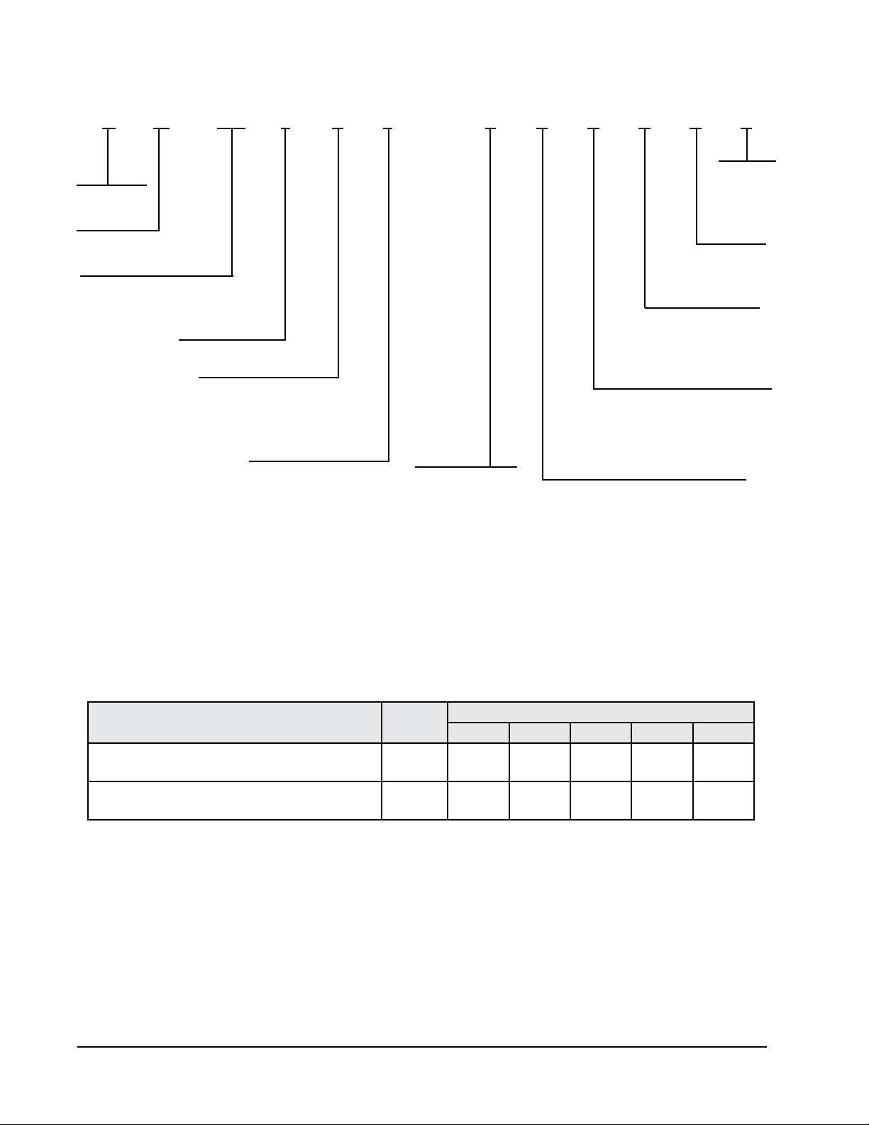
GEO WATER-TO-WATER HEAT PUMP MODEL NUMBER NOMENCLATURE
TABLE 1
RATED FLOW RATES FOR VARIOUS FLUIDS
APPLICATION SOURCE MODEL
GW024 GW036 GW048 GW060 GW070
Ground Loop (15% Methanol, Propylene, Glycol, etc. Loop
Load
7
7
9
9
11
11
13
13
15
16
Ground Water Loop
Load
7
7
9
9
11
11
13
13
15
16
G W 048 1 S 1 —A X R C C X
No. of Compressors
Compressor Type
S = Step Capacity
Water-to-Water
Geothermal
Options
X = None
Voltage
A = 230/208-60-1
Capacity MBTUH
024
036
048
060
070
Revision Level
Hot Water Generator Option
X = No HWG
1 = HWG & Pump
Reversible Option
H = Heating Only (Phase 2 Release)
R = Reversible (Phase 1 Release)
Source Coax
C = Copper (closed loop)
N = Cupronickel (open loop)
Load Coax
C = Copper
Loop circulating pumps – Source & Load are eld-installed external of the GSH unit for ease of installation, maintenance and service.

Manual 2100-583G
Page 5 of 48
TABLE 2
ELECTRICAL SPECIFICATIONS
TABLE 3
SOURCE SIDE WATER COIL PRESSURE DROPS
(Based upon 15% Methanol in Heating Mode @ 50°F)
+75°C copper wire ++ HACR type circuit breaker
MODEL GW024 GW036 GW048 GW060 GW070
Electrical Ratings (Volts/Hz/Phase) 208/230-60-1
Operating Voltage Range 253-197 VAC
Minimum Circuit Ampacity 16.9 21.4 28.8 36.1 39.4
+Field Wire Size 10 8 6 6 6
Ground Wire Size 12 12 10 10 10
++Delay Fuse of Circuit Breaker Max. 25 35 50 60 60
COMPRESSOR
Volts 208/230-60-1
Rated Load Amps (230/208) 8.2 / 9.2 12.2 / 14.0 17.6 / 20.3 21.8 / 24.1 29 / 32
Branch Circuit Selection Current 11.7 15.3 21.2 27.1 29.7
Locked Rotor Amps (230/208) 58.3 83.0 104.0 152.9 179.2
Flow Center (Based upon DORFC-2)
Volts 208/230-60-1
Amps 2.14
Desuperheat Pump Motor
Volts 208/230-60-1
Amps 0.15
Model
GPM
GW024 GW036 GW048 GW060 GW070
PSID Ft. Hd. PSID Ft. Hd. PSID Ft. Hd. PSID Ft. Hd. PSID Ft. Hd.
4 .93 2.15
5 1.55 3.58 1.57 3.62
6 2.17 5.01 2.19 5.05 1.63 3.75
7 2.79 6.44 2.81 6.48 2.21 5.10
8 3.48 8.03 3.56 8.21 2.80 6.45 1.76 4.06
9 4.17 9.62 4.31 9.94 3.38 7.80 2.20 5.08
10 0 5.18 11.95 4.12 9.49 2.64 6.09 2.6 6.07
11 6.05 13.96 4.85 11.19 3.08 7.11 3.1 7.17
12 5.70 13.15 3.58 8.25 3.6 8.28
13 6.55 15.11 4.07 9.39 4.1 9.39
14 4.63 10.67 4.6 10.58
15 5.18 11.95 5.1 11.77
16 5.74 13.23 5.7 13.12
17 6.3 14.46
18 6.9 15.81

Manual 2100-583G
Page 6 of 48
DSH INLET
SOURCE OUTLET
SIDE
LOAD OUTLET
DSH OUTLET
LOAD INLET
FRONT
SOURCE INLET
TOP
B D
26 5/16"
2 13/16"
11 5/8"
14 5/8"
A
C
33 3/8"
2 13/16"
E
5 5/8"
F
MIS-3160
UNIT A B C D E F
GW024 19 1/2" 3 1/2" 5 3/8" 5 1/2" 19 7/16" 3 9/16"
GW036 19 1/2" 3 1/2" 5 3/8" 5 1/2" 19 7/16" 3 1/2"
GW048 20 5/16" 3 1/2" 5 5/16" 5 7/16" 20 5/16" 3 11/16"
GW060 21 3/8" 2 3/4" 5 1/4" 5 1/8" 21 3/8" 3"
GW070 24 1/8" 2 3/4" 5 1/8" 5" 24 1/16" 2 5/8"
HIGH VOLTAGE
ENTRANCES
LOW VOLTAGE
ENTRANCES
19.044
1.357
19.044
20.763
1.357
20.763
28.296
FIGURE 1 – UNIT DIMENSIONS

Manual 2100-583G
Page 7 of 48
APPLICATION AND LOCATION
GENERAL
Each unit is shipped internally wired, requiring both ground-
source and load-side water piping, aquastat wiring, 230/208
volt AC power wiring, and optional desuperheater piping.
The equipment covered in this manual is to be installed by
trained, experienced service and installation technicians.
These instructions and any instructions packaged with any
separate equipment required to make up the entire heat
pump system should be carefully read before beginning
the installation. Note particularly any tags and/or labels
attached to the equipment.
While these instructions are intended as a general
recommended guide, they do not in any way supercede any
national and/or local codes. Authorities having jurisdiction
should be consulted before the installation is made.
SHIPPING DAMAGE
Upon receipt of the equipment, the carton should be checked
for external signs of shipping damage. If damage is found,
the receiving party must contact the last carrier immediately,
preferably in writing, requesting inspection by the carrier’s
agent.
APPLICATION
Capacity of the unit for a proposed installation should be
based on heat loss calculations made in accordance with
methods of the Air Conditioning Contractors of America.
The piping systems should be installed in accordance all
local, state, and federal requirements, and to the references
included on Page 3 of this document.
LOCATION
The unit may be installed in a basement, closet, or utility
room provided adequate service access is ensured, and
equipment will not freeze.
These units are not approved for outdoor installation
and therefore must be installed inside structure being
conditioned. Do not locate in areas subject to freezing in
the winter, or subject to sweating in the summer.
Prior to setting the unit, consider ease of piping and electrical
connections for the unit. Also for units which will be used
with a desuperheater, consider the proximity of the unit to
the water heater or storage tank. Place the unit on a solid
base, preferably concrete, to minimize undesirable noise and
vibration. DO NOT elevate the base pan on rubber or cork
vibration eliminator pads as this will permit the unit base to
act like a drum, transmitting objectionable noise.
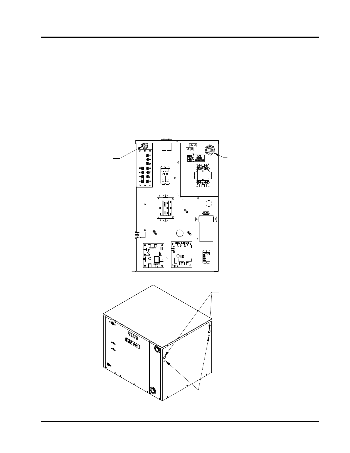
UNIT STACKING
The GW-Series products are designed to allow them to
be stacked up to three units high to lower the amount of
installed square footage requirements. Included with unit
are tie plates to secure the units together once they are
stacked. Remove, then replace the bottom three (3) screws
from bottom sides of the upper unit, and the top of the
lower unit to apply the tie plate. NOTE: The tie plates
are secured to the front of the control panel cover for
shipment.
ADDITIONAL CONSIDERATION
As an additional measure of safety in regard to the structure,
consider installing a drain pan with an alarm switch
underneath this water-bearing equipment.
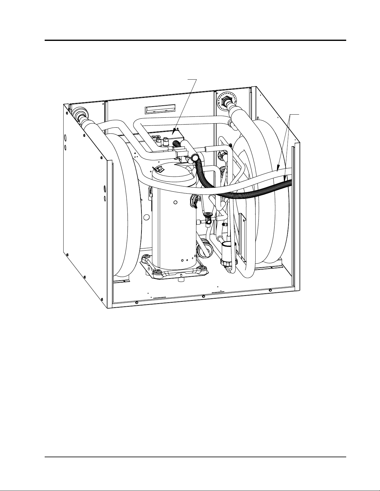
REQUIRED STEPS AFTER FINAL
PLACEMENT
The compressor is secured to the unit base for shipping.
Although the unit will perform as designed with the
compressor secured in place, there may be noticeable
additional noise and vibration. To obtain the lowest noise
and vibration levels, remove the compressor shipping
brackets after the unit is in its nal operating location.
To gain access to the compressor shipping brackets, remove
both the front and rear service panels. The brackets have
“hot pink” labels and are located on the compressor double
isolation base at the front and rear of the compressor. The
brackets are secured to the unit base with two (2) screws,
and secured to the isolation plate with a ¼" nut. Remove
and dispose of the two (2) screws and brackets. Reinstall
¼" nut once bracket is removed.
NOTE: MODELS COVERED BY THIS INSTALLATION MANUAL ARE NOT FOR USE AS A
POOL HEATER OR IN MARINE APPLICATIONS

Manual 2100-583G
Page 8 of 48
ALL GEOTHERMAL EQUIPMENT IS DESIGNED FOR
INDOOR INSTALLATION ONLY. DO NOT INSTALL OR
STORE UNIT IN A CORROSIVE ENVIRONMENT OR IN
A LOCATION WHERE TEMPERATURE AND HUMIDITY
ARE SUBJECT TO EXTREMES. EQUIPMENT IS NOT
CERTIFIED FOR OUTDOOR APPLICATIONS. SUCH
INSTALLATION WILL VOID ALL WARRANTIES.
FAILURE TO FOLLOW THIS CAUTION MAY RESULT
IN PERSONAL INJURY. USE CARE AND WEAR
APPROPRIATE PROTECTIVE CLOTHING, SAFETY
GLASSES AND PROTECTIVE GLOVES WHEN
SERVICING UNIT AND HANDLING PARTS.
BEFORE DRILLING OR DRIVING ANY SCREWS INTO
CABINET, CHECK TO ENSURE SCREW WILL NOT HIT
ANY INTERNAL PARTS, REFRIGERANT LINES, WATER
LINES, OR ELECTRICAL WIRES/COMPONENTS.
ANSI Z535.5 Denitions:
• DANGER (color RED): Indicate[s] a hazardous situation
which, if not avoided, will result in death or serious injury.
The signal word “DANGER” is to be limited to the most
extreme situations. DANGER [signs] should not be used
for property damage hazards unless personal injury risk
appropriate to these levels is also involved.
• WARNING (color ORANGE): Indicate[s] a hazardous
situation which, if not avoided, could result in death or
serious injury. WARNING [signs] should not be used
for property damage hazards unless personal injury risk
appropriate to this level is also involved.
• CAUTION (color YELLOW): Indicate[s] a hazardous
situation which, if not avoided, could result in minor or
moderate injury. CAUTION [signs] without a safety alert
symbol may be used to alert against unsafe practices that
can result in property damage only.
• NOTICE (color BLUE): [this header is] preferred to
address practices not related to personal injury. The safety
alert symbol shall not be used with this signal word. As an
alternative to “NOTICE” the word “CAUTION” without the
safety alert symbol may be used to indicate a message not
related to personal injury.
Manual 2100-583G
Page 9 of 48
MIS-3161
3/4" CONDUIT CONNECTION TO
INTERNAL CONTROL PANEL FOR
LINE POWER, AND FLOW CENTER
1/2" PLASTIC CONDUIT
CONNECTION TO LOW VOLTAGE
TERMINAL STRIP
WIRE ROUTING TO CONTROL PANEL
CENTER POWER
LIQUID-TITE CONDUIT FOR
POWER ENTRANCE & FLOW
ENTRANCE POINTS FOR 3/4"
ENTRANCE POINTS FOR 1/2"
PLASTIC CONDUIT FOR
CONTROL WIRING TO AQUA-STAT
FIGURE 2
WIRE ROUTING TO CONTROL PANEL
POWER & CONTROL WIRING
HIGH VOLTAGE LINE SUPPLY
Supplied with the unit is an adequate length of ¾" liquid-tite
conduit and ttings to run internally within the sheet metal
chassis from the control panel to one of four (4) 1⅛" holes
in the chassis sides (front/rear corners) for line voltage wires
to be ran through. See Figures 2 & 4.
LOW VOLTAGE CONTROL WIRES
Supplied with the unit is an adequate length of ½" plastic
conduit and ttings to run internally within the sheet metal
chassis from the low voltage box to one of four (4) ⅞" holes
in the chassis sides (front/rear corners) for thermostat wires
to be ran through. See Figures 2 & 4.
Manual 2100-583G
Page 10 of 48
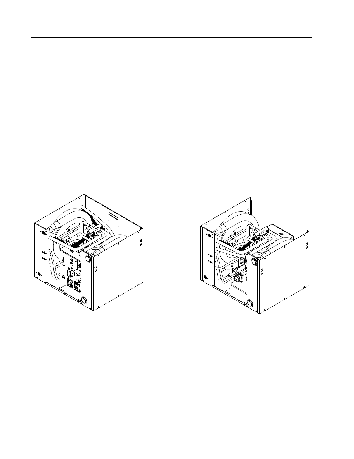
MIS-3163
FRONT - AS SHIPPED LOCATION
CONTROL PANEL LOCATIONS
OPTIONAL REAR LOCATION
FIGURE 3
CHANGING WATER ENTRANCE LOCATION (FRONT TO REAR)
BY RELOCATING CONTROL PANEL
RELOCATABLE CONTROL PANEL
The control panel of the GW-Series products can be
relocated to best suit the installation. It is factory shipped
where the control panel is located on the same side of the
unit the water connections are located. NOTE: the control
panel can be moved to the rear of the unit opposite to
where the water connections are located. See Figure 3.
1. Remove both front and rear service panels.
2. Remove control panel cover.
3. Remove four (4) screws securing control panel to
unit base.
4. Lift and turn control panel sideways guiding it
along the right side of the compressor toward the
rear of the unit.
5. Re-secure to unit base at new location.
Manual 2100-583G
Page 11 of 48
CONTROL PANEL
CONDUITS
MIS-3162
FIGURE 4
WIRE ENTRANCE CONDUITS
POWER & CONTROL WIRING
The GW-Series Geothermal Water-to-Water Heat Pumps
contain 2-stage compressors. This will need to be thought
through in planning and ordering the Aquastat control.
The two-stage compressor will not necessarily affect
the net water temperature, but can give great benet of
reducing the required number of compressor cycles,
especially under lower-load conditions.
In selecting the Aquastat, and depending upon the
particular installation, there are different ways to utilize
this.
1. Select an Aquastat with an outdoor temperature
sensor, and program the Aquastat to only energize
the “Y2” signal when outdoor temperatures fall
below a certain level.
2. Program a length of time to offset Stage #2 being
energized following Stage #1 call. This will
increase system run time/thermal consistency, and
minimize the start/stop cycles on the compressor,
and minimize short cycling.
3. Program the Aquastat to only energize “Y2” when
temperature of water cannot be held or increased
with only “Y1” energized (only bring on “Y2” with
further temperature fall).
4. A jumper can be installed from “Y1” to “Y2”
changing the system to a single stage system.
However, this is not recommended for longevity of
equipment service life or energy efciency.
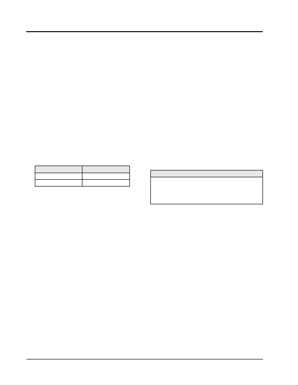
TABLE 4
OPERATING VOLTAGE RANGE
TAP RANGE
240V 253 - 216
208V 220 - 187
LOW VOLTAGE CONNECTIONS FOR DDC CONTROLS
Heating Part Load Energize
“Y1”
Heating Full Load Energize
“Y1”, “Y2”
Cooling Part Load Energize
“Y1”, “O”
Cooling Full Load Energize
“Y1”, “Y2”, “O”
Manual 2100-583G
Page 12 of 48
NOTE: The voltage should be measured at the eld power
connection point in the unit, and while the unit is operating at full
load (maximum amperage operating conditions).
WIRING – LOW VOLTAGE WIRING
UNIT MAIN POWER WIRING
This equipment requires a nominal 208/230-60-1 power
supply for proper operation. Line voltage connections are
made at the compressor contactor as noted by the wiring
diagram. Unit main power will route into the control
panel to the contactor through the supplied 3/4" Liquid
Tite conduit from one of the four (4) selectable electrical
entrance points.
230/208, 1-PHASE & 3-PHASE
EQUIPMENT DUAL PRIMARY VOLTAGE
TRANSFORMERS
All Equipment leaves the factory wired on 240 Volt
transformer tap. For 208 Volt operation, reconnect from
240 Volt to 208 Volt tap. The acceptable operating voltage
range for the 240V and 208V transformer taps are as noted
in Table 4.
For low voltage connections between the Aquastat and
the geothermal heat pump, a low voltage terminal strip is
factory mounted in the heat pump.
LOW VOLTAGE CONNECTIONS
These units use a grounded 24V AC low voltage circuit.
“R” terminal is 24 VAC hot.
“C” terminal is 24 VAC grounded.
“Y1” terminal is the compressor part load input.
“Y2” terminal is the compressor full load input (“Y1”
must also be energized along with “Y2”).
“O” terminal is the reversing valve input. The reversing
valve must be energized for cooling mode.
“A” terminal is 24 VAC output to external ow center
control, or to source water solenoid coil.
“L” terminal is compressor lockout output. This
terminal is activated on a high pressure, low pressure, or
ow switch trip on the Geothermal Logic Control. This
is a 24 VAC output.
Manual 2100-583G
Page 13 of 48
NOTE: All double o-ring ttings require “hand
tightening only”. Do not use a wrench or pliers as
retainer nut can be damaged with excessive force.
NOTE: Apply provided petroleum jelly to o-rings to
prevent damage and to aid in insertion.
PIPING ACCESS TO UNIT
Water Piping to and from the unit enters the unit cabinet on
either the front or rear-side through the ability to relocate the
control panel. See Figure 3 of the cabinet.
LOOP CONNECTIONS are a special double o-ring tting
with a retainer nut that secures it in place. (It is the same
style of tting used for the ow center connection on ground
loop applications.)
Various ttings are available so you may then connect to the
unit with various materials and methods. These methods
include 1" barbed tting (straight and 90°), 1" MPT (straight
and 90°), and 1¼" hot fusion tting (straight only). See
Product Specication Sheet.
LOAD CONNECTIONS are standard 1" Female Pipe
Thread allowing for any standard 1" Male Pipe Threaded
ttings to be utilized to make the connection.
DESUPERHEATER CONNECTIONS are standard ½"
Female Pipe Thread allowing for any standard ½" Male Pipe
Threaded ttings to be utilized to make the connection.
t x Qheatsource
v =
500 x T
10 x 50,000
v = = 50 gallons
500 x (120-100)
Manual 2100-583G
Page 14 of 48
LOAD SIDE WATER CONNECTIONS
The use of a buffer tank is highly recommended on the
load side of the GW-Series Water-to-Water heat pumps.
If heat pump sizing at all the various conditions is not
perfectly matched to the load, you are likely to short cycle
the refrigerant system on high or low pressure controls.
Buffer tanks provide thermal mass that allows the rate of
generation by the heat source to be signicantly different
from the rate of dissipation by the distribution system. They
are an essential component in any hydronic system that uses
a low thermal mass on/off heat source in combination with a
multiple-zone application.
SIZING BUFFER TANKS FOR ZONED
SYSTEMS
The required volume of a buffer tank depends on the rate of
heat input and release, as well as the allowed temperature
rise of the tank from when the heat source is turned on, to
when it is turned off. The greater the tanks volume, and the
wide the operating temperature differential, the longer the
heat source cycle length.
The following fomula can be used to calculate the volume
necessary when given a specied minimum heat source on-
time, tank operating differential, and rate of heat transfer:
Where:
v = required volume of the buffer tank (gallons)
t = desired duration of the heat source’s “on cycle”
(minutes)
Qheatsource = heat output rate of the heat source (Btu/h)
Qload = rate of heat extraction from the tank (Btu/h)
DT = temperature rise of the tank from when the heat source
is turned on to when it is turned off (°F).
For example, assume it’s desired that a heat pump operates
with a minimum compressor on-cycle duration of 10
minutes. The heat pump, when on, supplies 50,000 Btu/h.
The compressor turns on when the buffer tank drops to
100°F, and off when the tank reaches 120°F. What is the
necessary buffer tank volume to accomplish this?
If a tank larger than the minimum required volume is used,
the on-cycle length could be increased, or the temperature
differential setpoint could be reduced
The wider the temperature differential, and the greater the
volume of the tank, the longer the heat source on-cycle will
be.
Manual 2100-583G
Page 15 of 48
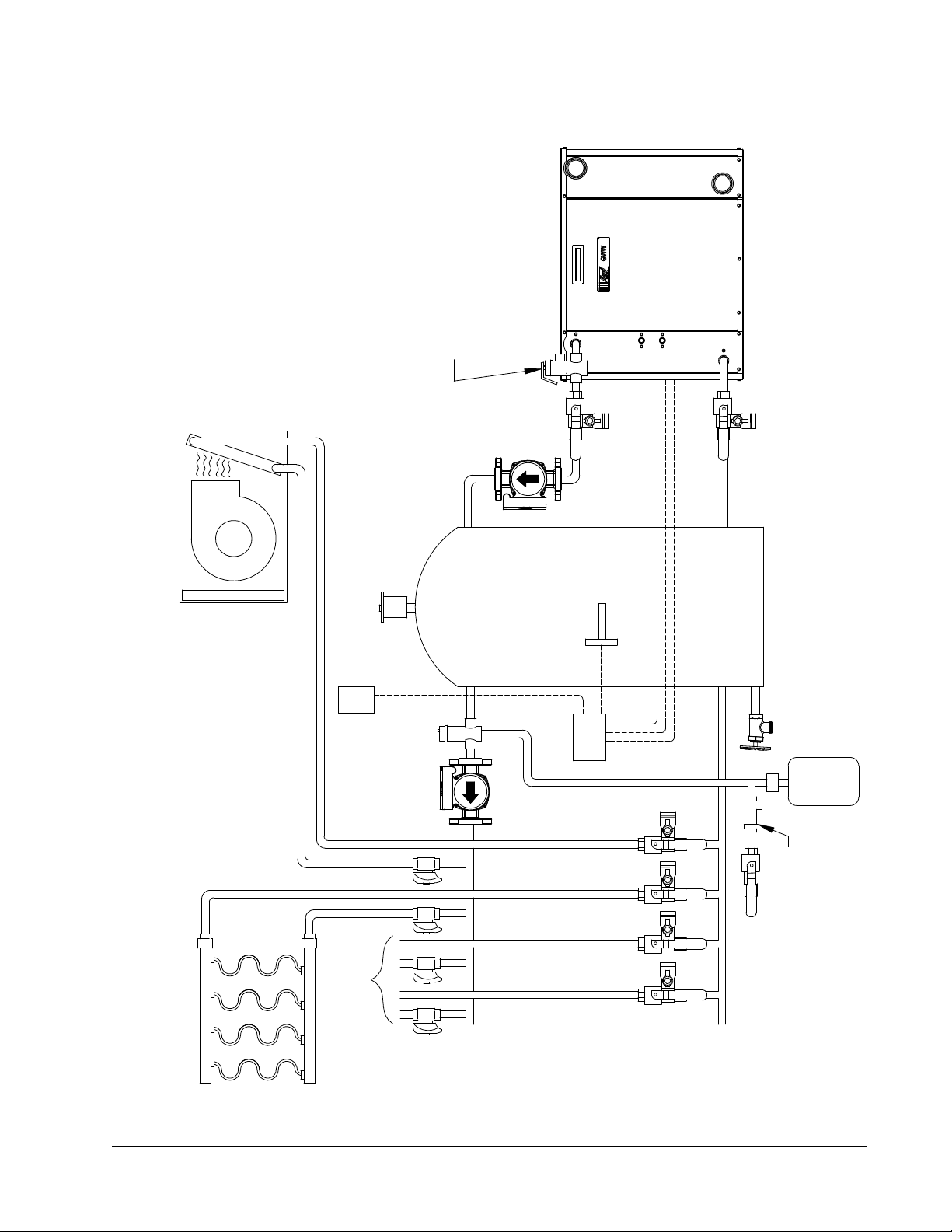
MAKE-UP-WATER
MIS-3164 A
HYDRONIC AIR HANDLER
AUTO AIR
RETURN
HEADER
PURGE
VALVES
ZONE
HEADER
VALVES
SUPPLY
BUFFER TANK
TEMPERATURE
ZONES
SENSOR
AQUA STAT
OUTDOOR
TO/FROM OTHER
TEMPERATURE
SEPARATOR
CIRCULATOR
SENSOR
AIR
CIRCULATOR
PURGE
VALVE
VALVE
PURGE
TANK
GEOTHERMAL HEAT PUMP
EXPANSION
PURGE
PRESSURE REDUCING
VALVE W/BACKFLOW
PREVENTER
NOTE: REQUIRES
PRESSURE/TEMPERATURE RELIEF
VALVE WITH TYPICAL 30 PSIG
SETPOINT. (MAY VARY BY LOCAL
CODE. CONSULT LOCAL CODES FOR
INSTALL REQUIREMENTS.)
FIGURE 5
A TYPICAL LOAD SIDE HYDRONIC SYSTEM
Manual 2100-583G
Page 16 of 48
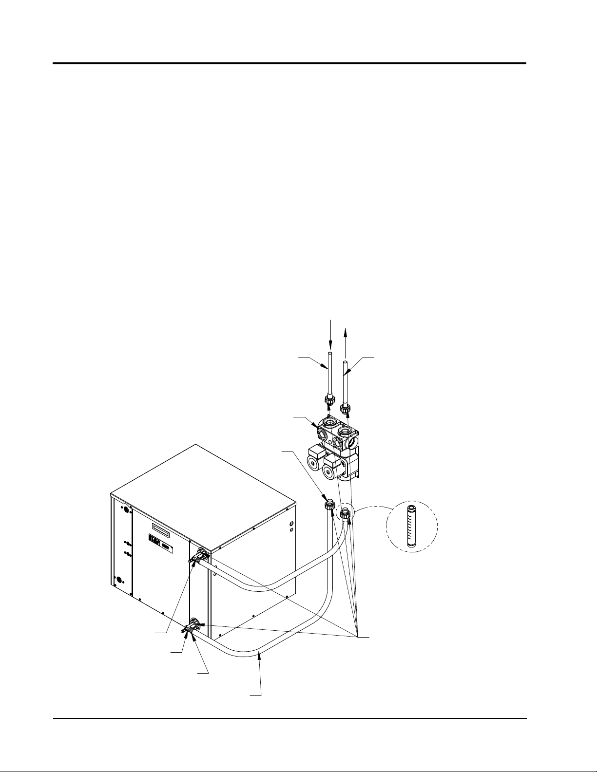
MIS-3165
BRASS ADAPTERS
PUMP MODULE
WATER IN
HOSE CLAMPS
STRAIGHT BARBED
WATER OUT
PIPE FROM
GOUND LOOP
GROUND LOOP
OPTIONAL VISUAL
PIPE TO
NOTE: IF USED SUPPORT
WITH A FIELD FABRICATED
WALL BRACKET
1" FLEXIBLE HOSE
FLOW METER
NOTE: APPLY PETROLEUM
JELLY TO O-RINGS TO PREVENT
DAMAGE AND AID ININSERTION
FIGURE 6
CIRCULATOR SYSTEM DESIGN
GROUND LOOP (EARTH COUPLED WATER LOOP APPLICATIONS)
NOTE: Unit shipped from factory with 75 PSIG low
pressure switch wired into control circuit and must be
rewired to 55 PSIG low pressure switch for ground
loop applications. This unit is designed to work on earth
coupled water loop systems, however, these systems operate
at entering water (without antifreeze) temperature with
pressures well below the pressures normally experienced in
water well systems.
THE CIRCULATION SYSTEM DESIGN
Equipment room piping design is based on years of
experience with earth coupled heat pump systems. The
design eliminates most causes of system failure.
The heat pump itself is rarely the cause. Most problems
occur because designers and installers forget that a ground
loop “earth coupled” heat pump system is NOT like a
household plumbing system.
Most household water systems have more than enough
water pressure either from the well pump or the municipal
water system to overcome the pressure of head loss in ½
inch or ¾ inch household plumbing. A closed loop earth
coupled heat pump system however, is separated from the
pressure of the household supply and relies on a small, low
wattage pump to circulate the water and antifreeze solution
through the earth coupled heat pump and equipment room
components.
The small circulator keeps the operating costs of the system
to a minimum. However, the performance of the circulator
MUST be closely matched with the pressure head loss of the
entire system in order to provide the required ow through
the heat pump. Insufcient ow through the heat exchanger
is one of the most common causes of system failure. Proper
system piping design and circulator selection will eliminate
the problem.
Manual 2100-583G
Page 17 of 48
10
120
110
100
90
80
70
60
50
40
30
20
0
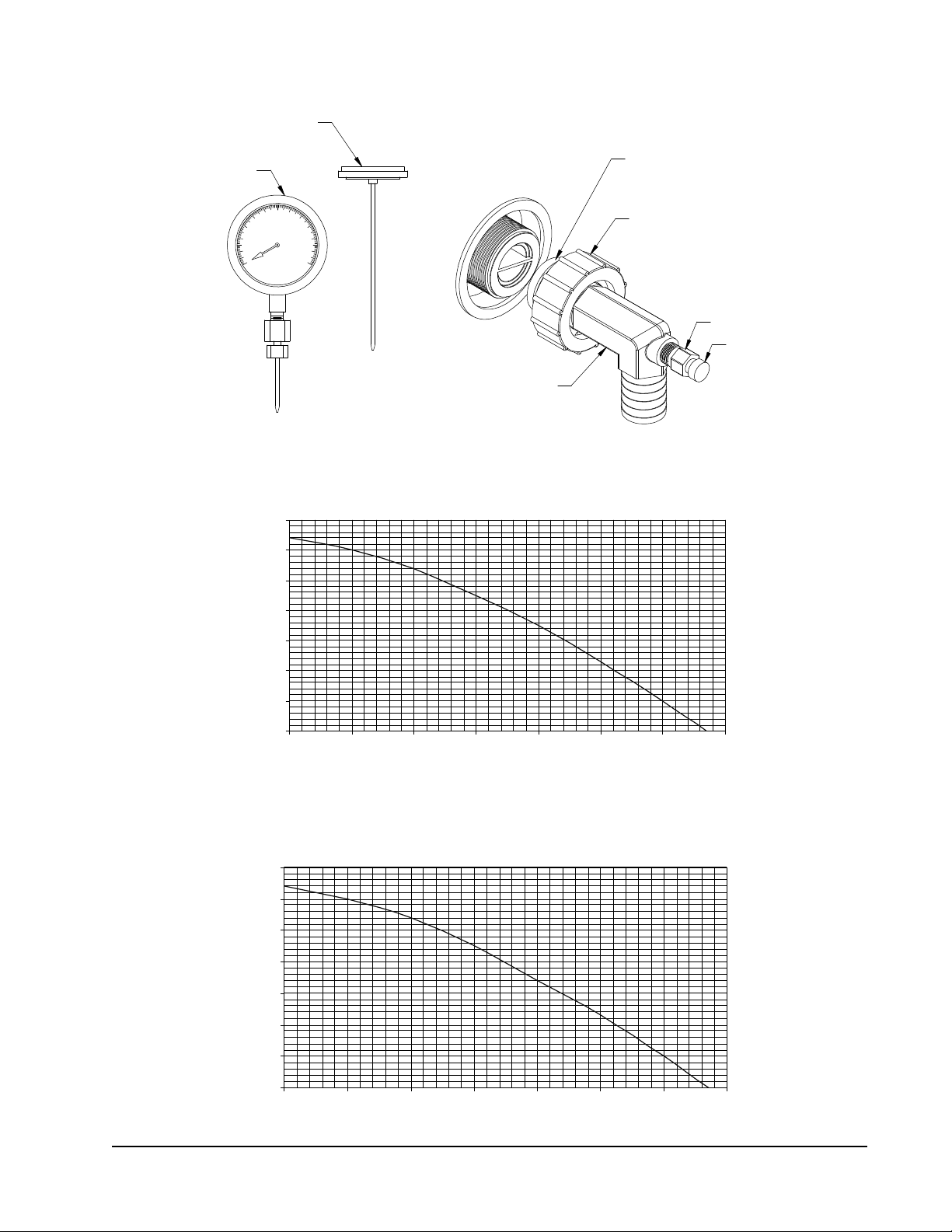
Retaining cap, hand tighten only
Pete's test plug
Test plug cap
Barbed 90° adapter
MIS-2622 A
NOTE: Slide retaining cap back to expose
double o-rings. Apply petroleum jelly to o-rings
to prevent damage and aid in insertion
with guage adaptor
Dial face pressure guage
Thermometer
Manual 2100-545
Page 18 of 38
0
10
20
30
40
50
60
70
0 5 10 15 20 25 30 35
Flow (GPM)
Head (Feet)
FIGURE 9
PERFORMANCE MODEL DORFC-2 FLOW CENTER
0
5
10
15
20
25
30
35
0 5 10 15 20 25 30 35
Flow (GPM)
Head (Feet)
FIGURE 8
PERFORMANCE MODEL DORFC-1 FLOW CENTER
FIGURE 7
10
120
110
100
90
80
70
60
50
40
30
20
0
Retaining cap, hand tighten only
Pete's test plug
Test plug cap
Barbed 90° adapter
MIS-2622 A
NOTE: Slide retaining cap back to expose
double o-rings. Apply petroleum jelly to o-rings
to prevent damage and aid in insertion
with guage adaptor
Dial face pressure guage
Thermometer
P/T
FIGURE 7A
FIGURE 7B
PERFORMANCE MODEL DORFC-1 FLOW CENTER
FIGURE 7C
PERFORMANCE MODEL DORFC-2 FLOW CENTER

Manual 2100-583G
Page 18 of 48
NOTE: It is highly recommended on ground water
systems (pump & dump) that a cupronickel coaxial coil
is utilized on the source side of the system. Not doing
so, may void the product warranty due to aggressive/
corrosive/highly oxygenated water attacking the copper
coaxial water coil.
NOTE: Unit shipped from factory with 75 PSIG low
pressure switch wired into control circuit for ground
water applications.
WATER CONNECTIONS
It is very important that an adequate supply of clean,
non-corrosive water at the proper pressure be provided
before installation is made. Insufcient water, in the
heating mode for example, will cause the low pressure
switch to trip, shutting down the heat pump. In assessing
the capacity of the water system, it is advisable that the
complete water system be evaluated to prevent possible
lack of water or water pressure at various household
xtures whenever the heat pump turns on. All plumbing
to and from the unit is to be installed in accordance with
local plumbing codes. The use of plastic pipe, where
pemissible, is recommended to prevent electrolytic
corrosion of the water pipe. Because of the relatively cold
temperatures encountered with well water, it is strongly
recommended that the water lines connecting the unit be
insulated to prevent water droplets from condensing on the
pipe surface.
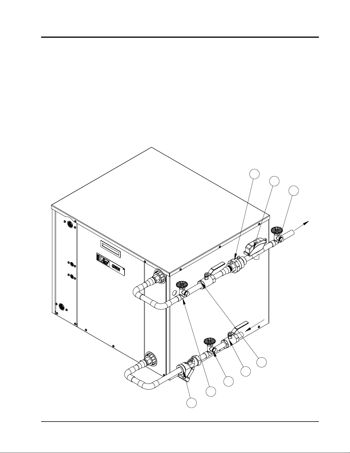
Refer to piping, Figure 8. Slow open/close Electrically
Actuated Valve with End Switch (2), 24V, provides on/off
control of the water ow to the unit. Refer to the wiring
diagram for correct hookup of the valve solenoid coil.
Constant Flow Valve (3) provides correct ow of water
to the unit regardless of variations in water pressure.
Observe the water ow direction indicated by the arrow on
the side of the valve body.
Strainer (8) installed upstream of water coil inlet to
collect foreign material which would clog the ow valve
orice.
The gure shows the use of shutoff valves (4) and (5), on
the in and out water lines to permit isoation of the unit
from the plumbing system should future service work
require this. Globe valves should not be used as shutof
valves because of the excessive pressure drop inherent in
the valve design. Instead, use either gate or ball valves as
shutoffs, so as to minimize pressure drop.
Hose bib (6) and (7), and tees should be included to permit
acid cleaning the refrigerant-to-water coil should such
cleaning be required. See WATER CORROSION.
Hose bib (1) provides access to the system to check water
ow through the constant ow valve to ensure adequate
water ow through the unit. A water meter is used to
check the water ow rate.
WELL PUMP SIZING
Strictly speaking, sizing the well pump is the
responsibility of the well drilling contractor. It is
important, however, the HVAC contractor be familiar with
the factors that determine what size pump will be required.
Rule of thumb estimates will invariably lead to under or
oversized well pumps. Undersizing the pump will result
in inadequate water to the whole plumbing system, but
with especially bad results to the heat pump - NO HEAT/
NO COOL calls will result. Oversized pumps will short
cycle and could cause premature pump motor or switch
failures.
The well pump must be capable of supplying enough
water and at an adequate pressure to meet competing
demands of water xtures. The well pump must be sized
in such a way that three requirements are met:
1. Adequate ow rate in GPM.
2. Adequate pressure at the xture.
3. Able to meet established ow rates and pressures
from the depth of the well-feet of lift.
GROUND WATER (WELL SYSTEM APPLICATIONS)
Manual 2100-583G
Page 19 of 48
6
1
2
3
4
5
7
8MIS-3166
FIGURE 8
WATER CONNECTION COMPONENTS
The pressure requirements put on the pump are directly
affected by the diameter of pipe being used, as well as the
water ow rate through the pipe. The worksheet included
in Manual 2100-078 should guarantee the well pump has
enough capacity. It should also ensure that the piping is
not undersized, which would create too much pressure due
to friction loss. High pressure losses due to undersized
pipe will reduce efciency and require larger pumps and
could also create water noise problems.
GROUND WATER (WELL SYSTEM APPLICATIONS)

Manual 2100-583G
Page 20 of 48
SYSTEM START UP PROCEDURE FOR
GROUND WATER APPLICATIONS
1. Be sure main power to the unit is OFF at disconnect.
2. Set thermostat system switch to OFF.
3. Move main power disconnect to ON. Except as
required for safety while servicing – DO NOT
OPEN THE UNIT DISCONNECT SWITCH.
4. Fully open the manual inlet & outlet valves, and
manually open water solenoid valve on the source side.
5. Check water ow.
a. Connect a water ow meter to the drain cock
between the constant ow valve and the solenoid valve.
b. Check the water ow rate through the constant ow
valve and the solenoid valve. Run a hose from the
ow meter to a drain or sink. Open the drain cock.
c. When water ow is okay, close the drain cock and
remove the water ow meter. The unit is now ready
to start.
6. Start the unit in heating mode by switching on the
Aquastat.
a. Make sure the water solenoid valve actuated/
opened.
7. Check the system refrigerant pressures against the
refrigerant pressure table located on the backside
of the system service door at the corresponding
source and load ow rates and enetering water
temperatures. If the refrigerant pressures do not
match, check for water ow issues, and then a
refrigeration system problem.
8. Switch the Aquastat/thermostat to cooling mode
and again verify water solenoid actuation, and
refrigerant pressures.
NOTE: If a charge problem is determined (high or low):
A. Check for possible refrigerant loss.
B. Reclaim all remaining refrigerant.
C. Evacuate unit down to 29" of vacuum.
D.
Recharge unit with refrigerant by weight to the serial
plate, as this is the only way to ensure proper charge.
WATER CORROSION
Two concerns will immediately come to light when
considering a water source heat pump, whether for ground
water or for a ground loop application: Will there be enough
water? And, how will the water quality affect the system?
Water quantity is an important consideration and one which
is easily determined. The well driller must perform a pump
down test on the well according to methods described
by the National Well Water Association. This test, if
performed correctly, will provide information on the rate
of ow and on the capacity of the well. It is important to
consider the overall capacity of the well when thinking
about a water source heat pump because the heat pump
may be required to run for extended periods of time.
The second concern, about water quality, is equally
important. Generally speaking, if the water is not offensive
for drinking purposes, it should pose no problem for
the heat pump. The well driller or local water softening
company can perform tests which will determine the
chemical properties of the water.
Water quality problems will show up in the heat pump in
one or more of the following ways:
• Decrease in water ow through the unit.
• Decreased heat transfer of the water coil (entering to
leaving water temperature difference is less).
There are four main water qualtiy problems associated with
ground water. These are:
1. Biological Growth This is the growth of microscopic
organisms in the water and will show up as a slimy deposit
throughout the water system. Shock treatment of the well
is usually required and this is best left to the well driller.
The treatment consists of injecting chlorine into the well
casing and ushing the system until all growth is removed.
2. Suspended Particles in the Water Filtering will
usually remove most suspended particles (ne sand, small
gravel) from the water. The problem with suspended
particles in the water is it will erode metal parts, pumps,
heat transfer coils, etc. As long as the lter is cleaned and
periodically maintained, suspended particles should pose
no serious problem. Consult with your well driller.
3. Corrosion of Metal Corrosion of metal parts results
from either highly corrosive water (acid water, generally
not the case with ground water), or galvanic reaction
between dissimilar metals in the presence of water. By
using plastic plumbing or dielectric unions, galvanic
reaction is eliminated. The use of corrosion resistant
materials such as a Cupronickel Water Coil through the
water system will reduce corrosion problems signicantly.
4. Scale Formation Of all the water problems, the
formation of scale by ground water is by far the most
common. Usually due to the formation of calcium
carbonate, but magnesium carbonate or calcium sulfate
may also be present. Carbon dioxide gas (CO2), the
carbonate of calcium and magnesium carbonate, is very
soluble in water. It will remain dissoved in the water
until some outside factor upsets the balance. This outside
inuence may be a large change in water temperature or
pressure. When this happens, enough carbon dioxide gas
combines with the dissolved calcium or magnesium in
the water and falls out of solution until a new balance is
reached. The change in temperature that this heat pump
produces is usually not high enough to cause the dissoved
gas to fall out of solution. Likewise, if pressure drops
are kept to a reasonable level, no precipitation of carbon
dioxide should occur.
GROUND WATER (WELL SYSTEM APPLICATIONS)
This manual suits for next models
4
Table of contents
Other BMC Heat Pump manuals

Popular Heat Pump manuals by other brands


Whirlpool
Whirlpool W2H3 installation instructions

Viessmann
Viessmann Vitovalor PT2 operating instructions

York
York YZF installation manual

Daikin
Daikin RQYQ140-180PY1 Service manual

ratiotherm
ratiotherm WP Max-Air Technical document

ClimateMaster
ClimateMaster Trilogy VE Series Installation, operation & maintenance instructions

Daikin
Daikin Altherma 3 R F User reference guide

Airwell
Airwell XDA user manual

Ecotec
Ecotec EAS SERIES Installation & user manual

Carrier
Carrier 50TCQD17-D24 Service and maintenance instructions

Daikin
Daikin Altherma 3 H HT EPRA18DAW1 Installer's reference guide

Trane
Trane FLEX HP HT Installation operation & maintenance