BMS 76604K8MPA User manual
Manual, HDMI 4K Series Camera, 76604K8MPA
The HDMI 4K Series Camera manual
9991002015 - manual Camera 76604K8MPA

Manual, HDMI 4K Series Camera, 76604K8MPA
Content
The HDMI 4K Series Camera Help Manual ................................................................................................................ 1
1The Application of the HDMI 4K Series Camera ................................................................................................ 1
2Available Ports on the Back of the Camera Body............................................................................................... 1
3HDMI 4K Camera Datasheet .............................................................................................................................. 2
4HDMI 4K Camera Function Description............................................................................................................. 2
4.1 Video Output ......................................................................................................................................... 2
4.2 Image Capture and Video Saving in SD card.......................................................................................... 2
4.3 ISP Function ........................................................................................................................................... 2
4.4 Image Operation Function..................................................................................................................... 2
4.5 Other Functions ..................................................................................................................................... 2
5HDMI 4K Camera Packing Information .............................................................................................................. 3
6Software and App.............................................................................................................................................. 4
7HDMI 4K Camera Application Configurations.................................................................................................... 4
7.1 Camera working standalone with built-in Onboard BMS software....................................................... 4
7.2 Connecting camera to the PC with USB3.0 port.................................................................................... 5
7.3 Camera working in WLAN mode (AP mode).......................................................................................... 6
7.4 Connecting camera to the PC with LAN port ........................................................................................ 8
7.5 Connecting multi-cameras to the router through the LAN port/WLAN STA mode for the network
application ....................................................................................................................................................... 10
8Brief Introduction of HDMI 4K UI and Its Functions ........................................................................................ 13
8.1 Onboard BMS UI .................................................................................................................................. 13
8.2 The camera control panel on the left side of the video window......................................................... 14
8.3 The Measurement Toolbar on top of the video window..................................................................... 15
8.4 Icons and functions of the Synthesis Camera Control Toolbar at the bottom of the video window... 17
9Sample Photos Captured with HDMI 4K Series Camera.................................................................................. 24
10 Contacting Customer Service....................................................................................................................... 27
The HDMI 4K Series Camera Help Manual
1/ 29
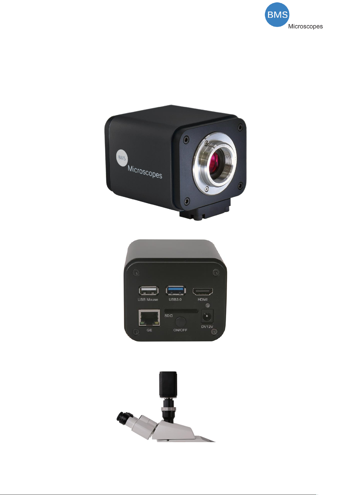
1 The Application of the HDMI 4K Series Camera
Figure 1-1 The HDMI 4K Camera
The HDMI 4K series camera is intended to be used for the acquisition of digital images from the stereo
microscope, biological microscope or online interactive teaching. The basic characteristic is listed as below:
⚫Sony Exmor back illuminated CMOS sensor
⚫4K HDMI/NETWORK/USB multiple video outputs
⚫4K/1080P auto switching according to the display resolution
⚫SD card/USB flash disk for the captured image and video storage
⚫Embedded Onboard BMS for the control of the camera
⚫With strong ISP and other related processing functions
⚫BMS_pix3 software for PC
⚫iOS/Android applications for smart phones or tablets
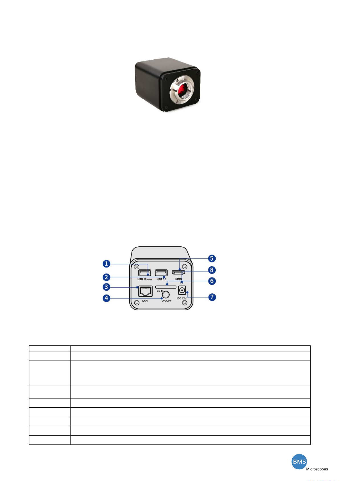
2 Available Ports on the Back of the Camera Body
Figure 2-1 Available Ports on the Back Panel of the Camera Body
Interface
Function Description
USB Mouse
Connect USB mouse for easy operation with embedded Onboard BMS software.
USB3.0
1. Connect USB flash drive to save pictures and videos.
2. Connect 5G WLAN modules to transfer video wirelessly in real time(AP/STA);
3. Connect computer with USB connection to transfer video in real time (Will be supported later);
HDMI
Comply with HDMI2.0 standard. 4K/1080P format video output and supporting automatic switch between 4K and 1080P
format according to the connected monitors.,
LAN
LAN port to connect router and switch to transfer video.
SD
Comply with SDIO3.0 standard and SD card could be inserted for video and images saving.
DC12V
Power adapter connection (12V/1A).
ON/OFF
Power switch.
LED
LED status indicator.

The HDMI 4K Series Camera Help Manual
2/ 29
3 HDMI 4K Camera Datasheet
Order Code
Sensor &
Size(mm)
Pixel
(μm)
G Sensitivity
Dark Signal
FPS/Resolution
Binni
ng
Exposure
(ms)
76604K8MPA
Sony IMX334(C)
1/1.8"(7.68x4.32)
2.0x2.0
505mv with 1/30s
0.1mv with 1/30s
60@3840*2160(HDMI)
30@3840*2160(NETWORK)
30@3840*2160(USB)
1x1
0.04~2000
4 HDMI 4K Camera Function Description
4.1 Video Output
Video Output Interface
Function Description
HDMI Interface
1. Comply with HDMI2.0 standard;
2. 60fps@4K or 60fps@1080P(XCAM4K8MPA); 30fps@4K or 60fps@1080P(XCAM4K16MPA);
LAN Interface
1. 30ps@4K resolution;
2. H264 encoded video;
3. Bandwidth adjustment in real time;
4. DHCP configuration or manual configuration;
5. unicast/multicast configuration;
WLAN Interface
Connecting 5G WLAN adapter(USB3.0 interface) in AP/STA mode;
USB3.0 Interface
1. Connecting USB3.0 port of PC for video transfer ;
2. MJPEG format video;
4.2 Image Capture and Video Saving in SD card
Function Name
Function Description
Video Saving
1. Video format:8M(3840*2160) H264 encoded MP4 file;
2. Video saving frame rate:50~60fps(XCAM4K8MPA) (related with SD card and video resolution)
Image Capture
8M (3840*2160, XCAM4K8MPA) JPEG/TIFF image in SD card or USB flash disk
Measurement Saving
1. Measurement information saved in different layer with image content。
2. Measurement information is saved together with image content in burn in mode.
4.3 ISP Function
Function Name
Function Description
Exposure / Gain
Automatic / Manual Exposure
White Balance
Manual / Automatic / ROI Mode
Sharpening
Supported
3D Denoise
Supported
Saturation Adjustment
Supported
Contrast Adjustment
Supported
Brightness Adjustment
Supported
Gamma Adjustment
Supported
50HZ/60HZ Anti-flicker
Function
Supported
4.4 Image Operation Function
Function Name
Function Description
Zoom In/Zoom Out
Up to 10X
Mirror/Flip
Supported
Freeze
Supported
Cross Line
Supported
PIP (Picture in Picture)
Supported
Compare
Comparison between real time video and images in SD card or USB flash drive
Embedded Files Browser
Supported
Video Playback
Supported
Measurement Function
Supported
4.5 Other Functions
Function Name
Function Description
Embedded RTC(Optional)
To support accurate time on board
Restore Factory Settings
Supported

The HDMI 4K Series Camera Help Manual
3/ 29
Multiple Language Support
English / Simplified Chinese / Traditional Chinese / Korean / Thai / French / German / Japanese / Italian
5 HDMI 4K Camera Packing Information
Figure 5-1 HDMI 4K Camera Packing Information
Standard Packing List
A
Gift box : L:25.5cm W:17.0cm H:9.0cm (1pcs, 1.43Kg/ box)
B
BMS 4K Camera
C
Power Adapter: Input: AC 100~240V 50Hz/60Hz, Output: DC 12V 1A
European standard:Model:GS12E12-P1I 12W/12V/1A; TUV(GS)/CB/CE/ROHS
EMI Standard:EN55022,EN61204-3, EN61000-3-2,-3, FCC Part 152 class B, BSMI CNS14338
EMS Standard:EN61000-4-2,3,4,5,6,8,11,EN61204-3,Class A Light Industry Standard
D
USB Mouse
E
HDMI 2.0 Cable
F
High-speed USB3.0 A male to A male gold-plated connectors cable /2.0m
G
CD (Driver & utilities software, Ø12cm)
H
SD Card(16G or above; Speed: class 10) or USB flash disk
I
USB WLAN adapter
J
Ethernet cable
K
L
Fixed lens adapter
C-Mount to Dia.23.2mm Eyepiece Tube
(Please choose 1 of them for your microscope)
FMA050
M
108015(Dia.23.2mm to 30.0mm Ring)/Adapter rings for 30mm eyepiece tube
N
108016(Dia.23.2mm to 30.5mm Ring)/ Adapter rings for 30.5mm eyepiece tube
O
Calibration kit
106013/TS-M7(X=0.01mm/100Div., 0.10mm/100Div.)

The HDMI 4K Series Camera Help Manual
4/ 29
6 Software and App
The software or the APP can be downloaded from the following link:
http://extern.bmsmicroscopes.com/BMS_pix3/BMS_pix3.rar
7 HDMI 4K Camera Application Configurations
You can use the HDMI 4K series camera in 5 different ways. Each application requires different hardware
environment.
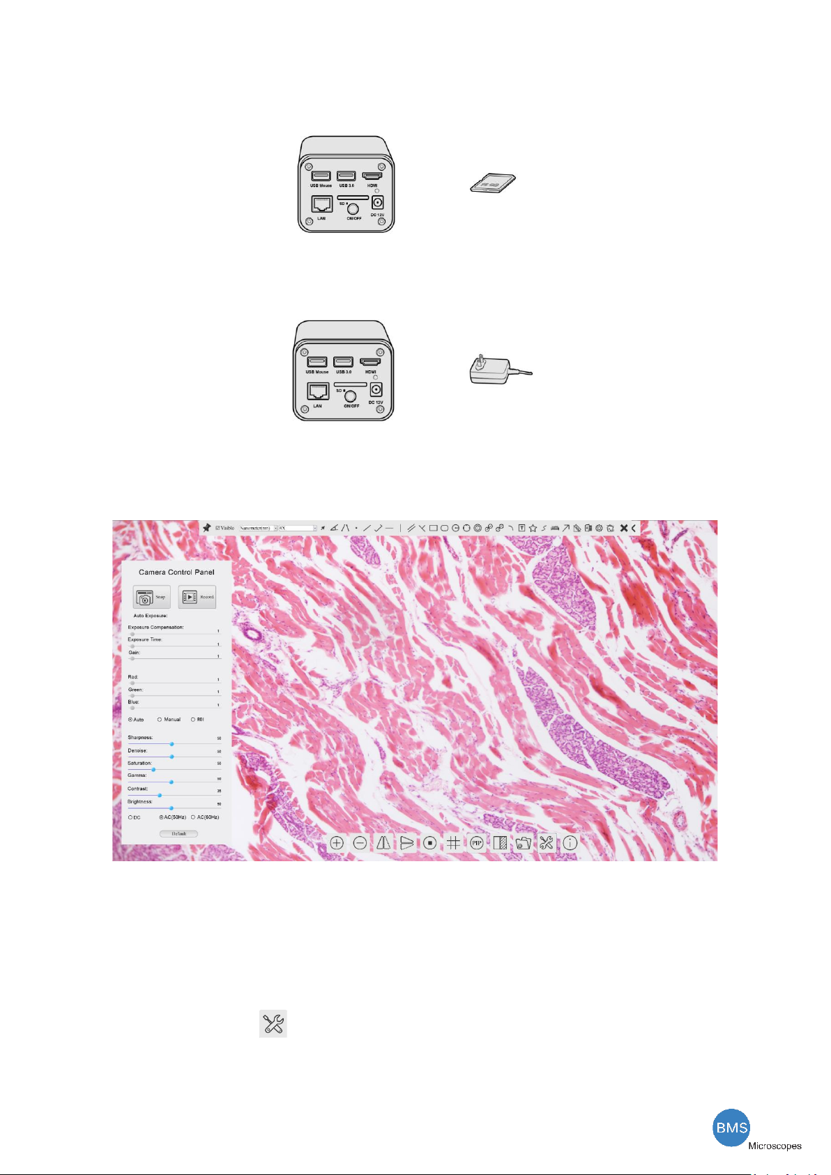
7.1 Camera working standalone with built-in Onboard BMS software
For this application, apart from the microscope, you only need an HDMI displayer, the supplied USB mouse
and the camera embedded Onboard BMS software. A computer or a network connection is not required to
operate the camera in this application. The steps to start the camera are listed as below:
Figure 7-1HDMI 4K Camera with the HDMI Displayer
⚫Connect the camera to a HDMI displayer using the HDMI cable;
⚫Insert the supplied USB mouse to the camera’s USB port;
The HDMI 4K Series Camera Help Manual
5/ 29
⚫Insert the supplied SD card/USB flash disk (USB3.0 interface) into the HDMI camera SD card
slot/USB3.0 interface;
⚫Connect the camera to the power adapter and switch it on;
⚫Switch on the displayer and view the video in the Onboard BMS software. Move the mouse to the left,
top or bottom of the Onboard BMS UI, different control panel or UI will pop up and users could operate with
the mouse at ease.
7.2 Connecting camera to the PC with USB3.0 port
For Windows user (Windows XP (32bit), Windows 7/8/10 (32/64 bit) ), please use BMS_pix3.
For macOS and Linux user (macOS 10.10 or above or Linux distributions with kernel 2.6.27 or higher), please use
latest version of BMS_pix3 from download.
The steps to start the camera are listed below:
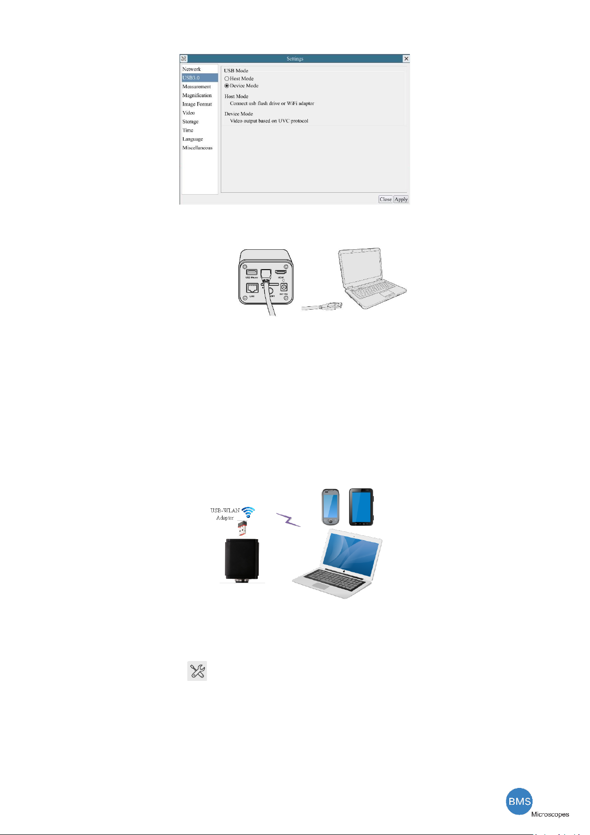
⚫Start the camera according to Sec. 7.1. After the camera is running, moving the mouse to the bottom
of the UI and clicking the button on the Synthesis Camera Control Toolbar at the bottom of the video
window, a small window called Settings will pop up as shown below. Click USB3.0 property page and choose
the Device Mode in USB Mode edit box(The factory default configuration is Device mode ).
The HDMI 4K Series Camera Help Manual
6/ 29
⚫Install the BMS_pix3 on your PC;
⚫Plug one end of USB cable into the camera’s USB3.0 port and the other end into the usb port of PC.
⚫Open BMS_pix3 software. The HDMI camera will be recognized automatically in software.
7.3 Camera working in WLAN mode (AP mode)
The PC should be a WLAN enabled one.
For Windows user (Windows XP (32bit), Windows 7/8/10 (32/64 bit) ), please use BMS_pix3.
For macOS and Linux user (macOS 10.10 or above or Linux distributions with kernel 2.6.27 or higher), please
use latest version of BMS_pix3 from download. When connecting the camera with a mobile device, the free
BMS_pix3 App is required. Just make sure that the mobile device uses iOS 11 or higher/Android 5.1 or higher
operating systems.
Figure 7-2 The PC or Mobile Device Connect to the Camera through WLAN
The steps to start the camera are listed below:
⚫Start the camera according to Sec. 7.1. After the camera is running, moving the mouse to the bottom
of the UI and clicking the button on the Synthesis Camera Control Toolbar at the bottom of the video
window, a small window called Settings will pop up as shown below. Click USB3.0 property page and choose
the Host Mode in USB Mode edit box(The factory default configuration is Device mode ). Click Network>WLAN
property page and choose the AP in the WiFi Mode edit box(The factory default configuration is AP mode ).

The HDMI 4K Series Camera Help Manual
7/ 29
⚫Install the BMS_pix3 on your PC or install the BMS_pix3 App on the mobile device;
⚫Plug the USB WLAN adapter into the camera’s USB3.0 port;
⚫Connect the PC or mobile device with the WLAN AP point that the camera provides; The network name
(SSID) and the WLAN password (The default one is 12345678) can be found on the camera’s
Setting>Network>WLAN page in AP mode
⚫Start the BMS_pix3 software or BMS_pix3 App and check the configuration. Normally, active HDMI 4K
cameras are automatically recognized. The live image of each camera is displayed. For the display, the
Camera List tool window is used in the BMS_pix3 software, and the Camera Thumbnail is used in the
BMS_pix3 App.
The HDMI 4K Series Camera Help Manual
8/ 29
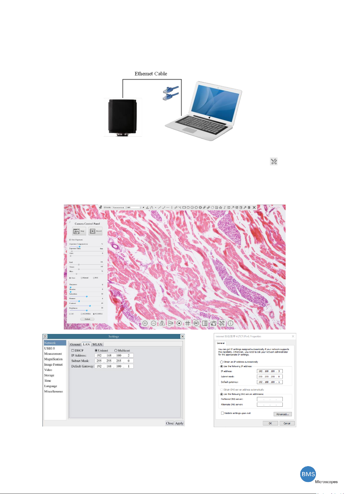
7.4 Connecting camera to the PC with LAN port
This application uses the camera as the network camera. User must configure the IP of the camera and PC
manually and ensure their IP addresses are in the same net. The subnet mask and gateway of the camera and PC
must be the same.
Figure 7-3 Connecting the HDMI 4K Camera with Ethernet Cable to the PC
⚫Start the camera according to Sec. 7.1 after the camera is running, clicking the button on the
Synthesis Camera Control Toolbar at the bottom of the video window, a small window called Settings will
pop up as shown below on the left side, clicking the LAN property page, uncheck the DHCP item. Input the
IP Address, Subnet Mask and Default Gateway for the camera. Designate the Internet Protocol Version 4
(TCP/IPv4) Settings page’s IP address on the PC with similar configuration as shown below on the right side
but with different IP address.
Figure 7-4 Configure the HDMI 4K Camera IP
Figure 7-5 Configure the PC’s IP
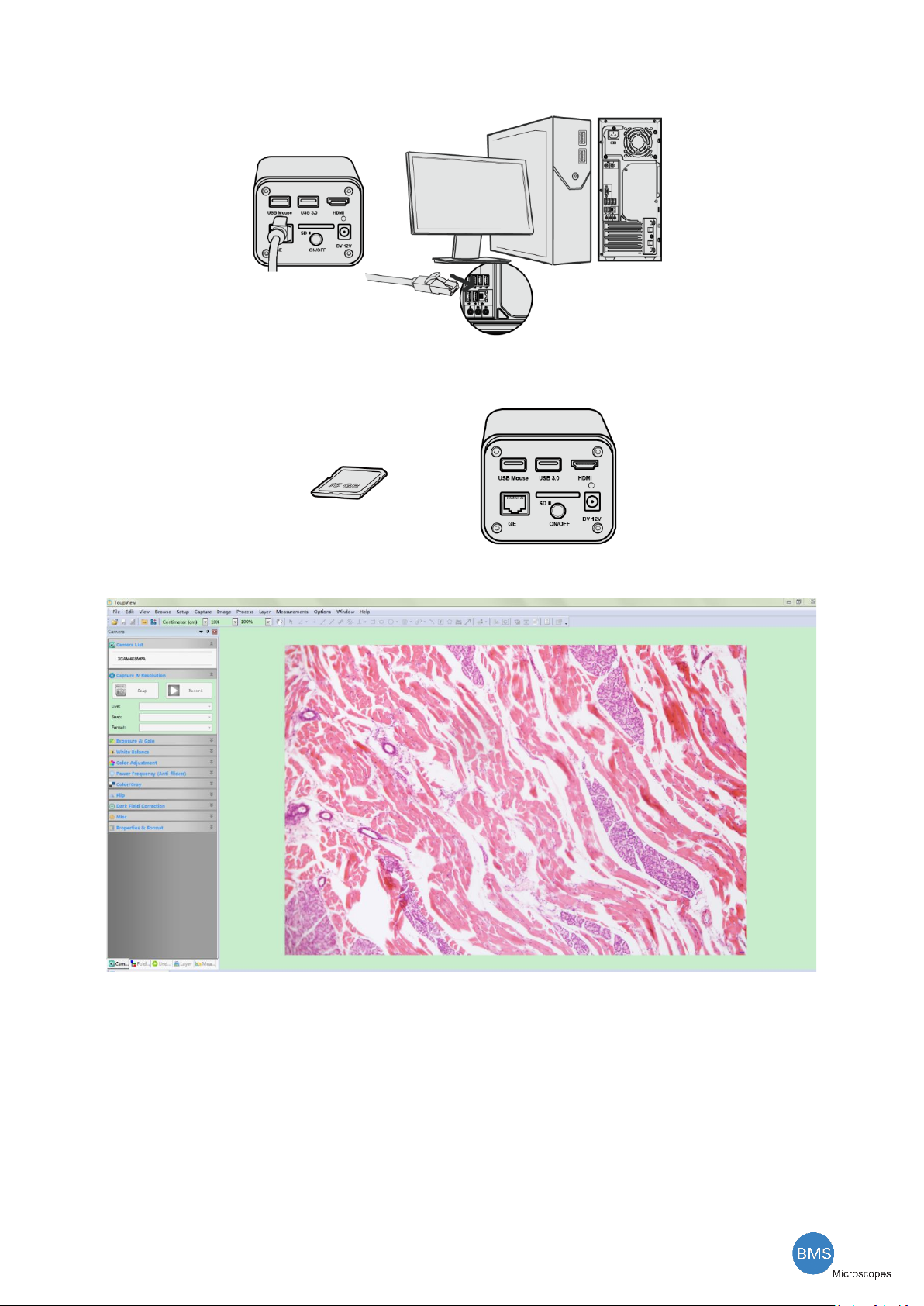
After the above configurations are finished, user can connect the HDMI 4K camera to the computer through
the USB to Ethernet adapter as shown below:
The HDMI 4K Series Camera Help Manual
9/ 29
⚫Connect the GE port with the Ethernet cable to the PC’s network port;
⚫Insert the supplied SD card/USB flash disk (USB3.0 interface) into the HDMI camera SD card
slot/USB3.0 interface;
⚫Install the BMS_pix3 on your PC or install the BMS_pix3 App on the mobile device; Run the software
BMS_pix3, clicking the camera name in the camera list starts the live video.
The HDMI 4K Series Camera Help Manual
10 / 29
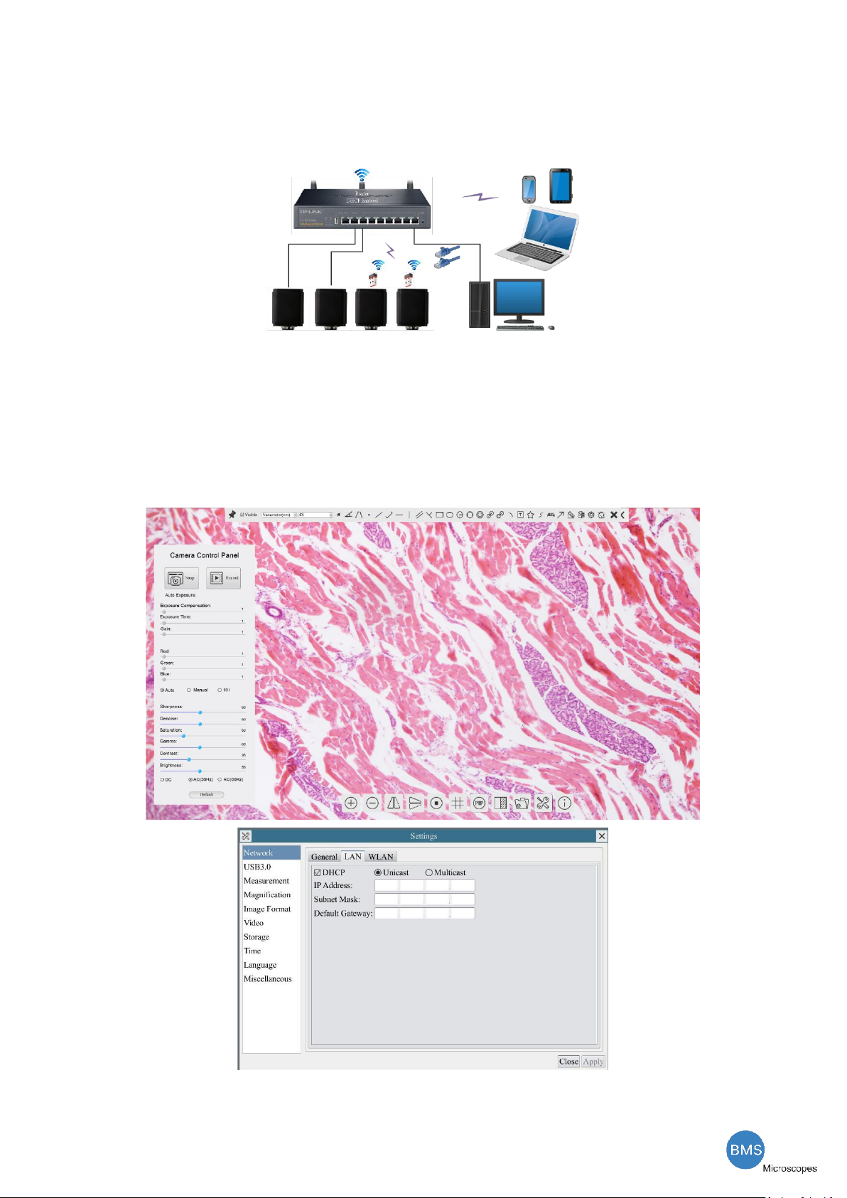
7.5 Connecting multi-cameras to the router through the LAN port/WLAN STA mode for the network
application
In LAN/WLAN STA mode, the camera connects to router by LAN port/WLAN STA mode. If a router with
LAN/WLAN capability is used, users could connect the router with Ethernet cable/WLAN and control the camera.
Figure 7-6 Multi HDMI 4K Cameras Connecting to the Router through the LAN Port/WLAN Style
⚫The connection and configuration are just the same as in Sec.7.1 or Sec. 7.4. But here, users need to
check DHCP. If Multicast is disabled or is not supported, users should only select Unicast. If Multicast is
supported by the network, users could select Multicast to achieve a better performance, especially in the
case that multi-users connecting to the same camera. In addition, please guarantee that the broadcasting
function is enabled in the network.
Active HDMI 4K camera recognized by the BMS_pix3 software or the BMS_pix3 App and they are displayed as
a camera list or thumbnail in the software or app.
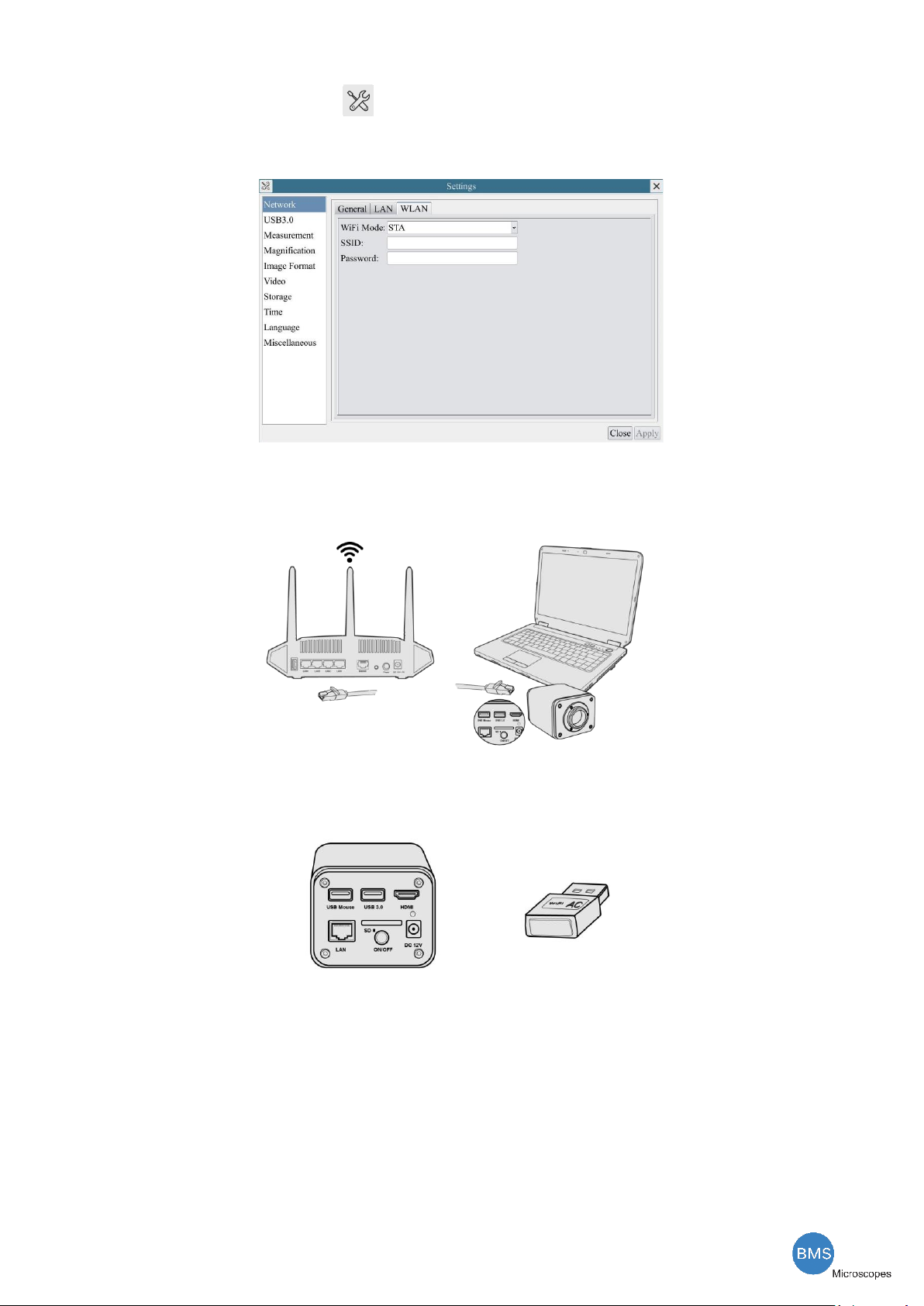
⚫Or start the camera according to Sec. 7.1. After the camera is running, moving the mouse to the
The HDMI 4K Series Camera Help Manual
11 / 29
bottom of the UI and clicking the button on the Synthesis Camera Control Toolbar at the bottom of the
video window, a small window called Settings will pop up as shown below. Clicking Network>WLAN
property page and choosing the STA in the WiFi Mode edit box(The factory default configuration is AP
mode ). Input the to be connected router’s SSID and Password as shown below:
⚫Install the BMS_pix3 software on your PC. Alternatively, install the free BMS_pix3 App on the mobile
device;
⚫Plug the Ethernet cable into the camera’s LAN port and the other end to the PC (for those connected to
router with WLAN STA mode );
⚫Or plug the USB WLAN adapter into the camera’s USB3.0 port(for those connected to router with
WLAN STA mode );
⚫Finally as shown below, 2 HDMI cameras are connected to the router with LAN cable and 2 HDMI
cameras are connected to the same router with WLAN STA mode(The number of the cameras, the
connection mode(LAN or WLAN STA)) connected to the router are determined by the router performance)

The HDMI 4K Series Camera Help Manual
12 / 29
⚫Make sure that your PC or your mobile device is connected to the LAN or WLAN of the router; Start the
BMS_pix3 software or BMS_pix3 App and check the configuration. Normally, active HDMI 4K cameras are
automatically recognized. The live image of each camera is displayed. For the display, the Camera List tool
window is used in the BMS_pix3 software, and the Camera Thumbnail is used in the BMS_pix3 App; Select
the HDMI 4K camera you are interested in. To do so, double click the camera’s name in the Camera List tool
window if you use the BMS_pix3 software; If you use the BMS_pix3 App, tap the camera’s thumbnail in the
Camera List page.
Note on data security
The data transfer of the HDMI 4K camera in LAN or WLAN is not encrypted. Anyone who is connected to the
network and has installed the BMS_pix3 software or BMS_pix3 App, can see the live image of all active HDMI 4K
cameras. Operate the camera with the Onboard BMS software, if you want to make sure that nobody in the
network can see the camera’s live image.
About the routers/switches
It is suggested that routers/switches supporting 802.11ac 5G segment should be selected to achieve better
wireless connection experience.
The HDMI 4K Series Camera Help Manual
13 / 29
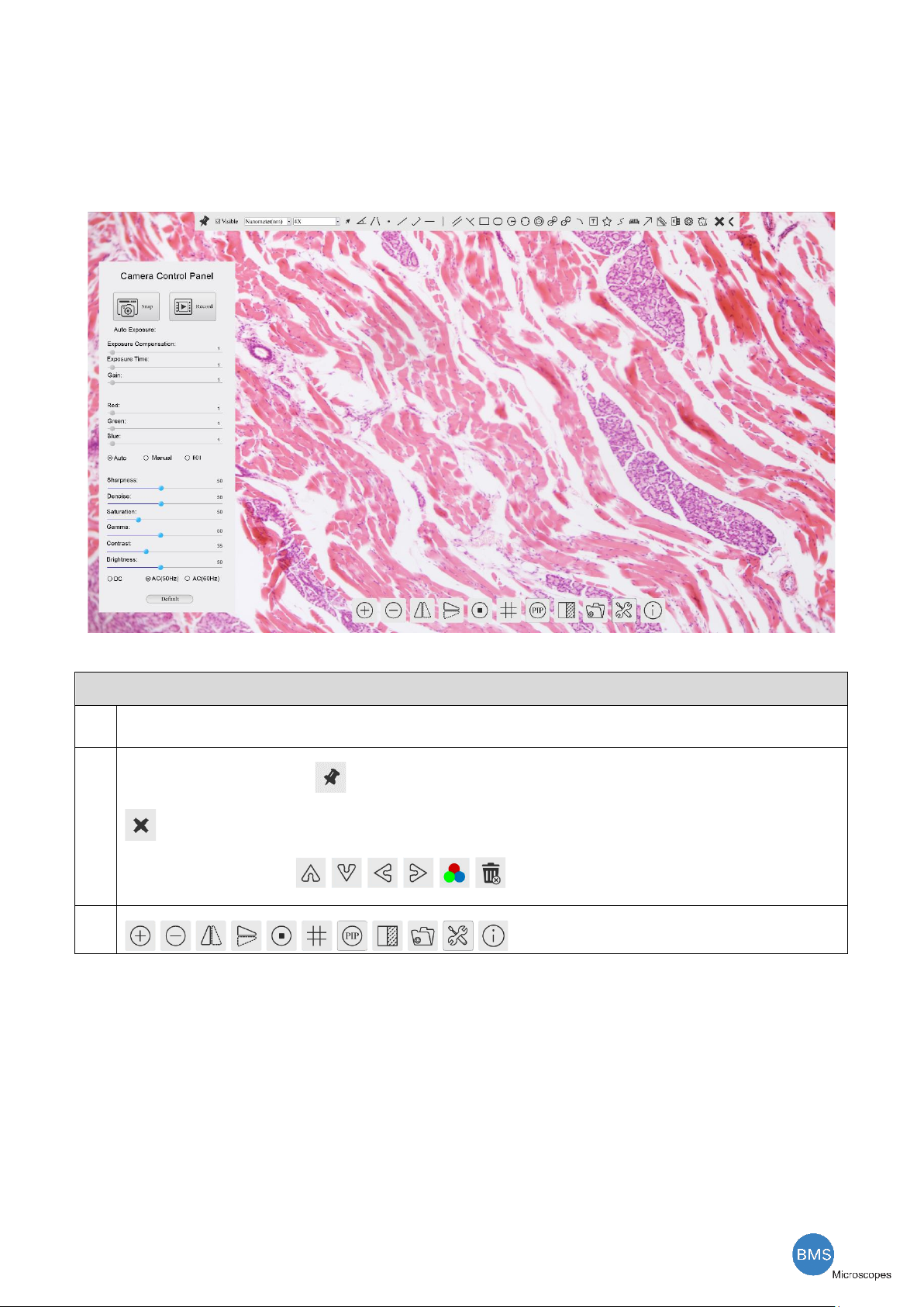
8 Brief Introduction of HDMI 4K UI and Its Functions
8.1 Onboard BMS UI
The HDMI 4K UI shown in Figure 8-1 includes a Camera Control Panel on the left of the video window, a
Measurement Toolbar on the top of the video window and a Synthesis Camera Control Toolbar on the bottom of
the video window.
Figure 8-1 The HDMI 4K Camera Control GUI
Notes
1
To show the Camera Control Panel, move your mouse to the left of the video window. See Sec.8.2 for details
2
Move the mouse cursor to the top of the video window, a Measurement Toolbar will pop up for calibration and measurement operations. When
user left-clicks the Float/Fixed button on the Measurement Toolbar, the Measurement Toolbar will be fixed. In this case the Camera
Control Panel will not pop up automatically even if users move mouse cursor to left side of the video window. Only when user left-clicks the
button on the Measurement Toolbar to exit from measuring procedure will they be able to do other operations on the Camera Control
Panel, or the Synthesis Camera Control Toolbar. During the measuring process, when a specific measuring object is selected, an Object
Location & Attributes Control Bar will appear for changing location and properties of the selected
object. See Sec.8.3 for details.
3
When users move mouse cursor to the bottom of the video window, the Synthesis Camera Control Toolbar will pop up automatically.
.See Sec.8.4 for details.

The HDMI 4K Series Camera Help Manual
14 / 29
8.2 The camera control panel on the left side of the video window
The Camera Control Panel controls the camera to achieve the best video or image quality according to the
specific applications; It will pop up automatically when the mouse cursor is moved to the left side of the video
window (in measurement status, the Camera Control Panel will not pop up. The Camera Control Panel will only
pop up when the measurement process is finished or terminated while user’s cursor on the left edge of the video
window). Left-clicking button to achieve Display/Auto Hide switch of the Camera Control Panel.
Camera Control Panel
Function
Function Description
Snap
Capture image and save it to the SD card
Record
Record video and save it to the SD card
Auto Exposure
When Auto Exposure is checked, the system will automatically adjust exposure time and
gain according to the value of exposure compensation
Exposure
Compensation
Available when Auto Exposure is checked. Slide to left or right to adjust Exposure
Compensation according to the current video brightness to achieve proper brightness value
Exposure Time
Available when Auto Exposure is unchecked. Slide to left or right to reduce or increase
exposure time, adjusting brightness of the video
Gain
Adjust Gain to reduce or increase brightness of video. The Noise will be reduced or
increased accordingly
Red
Slide to left or right to decrease or increase the proportion of Red in RGB on video
Green
Slide to left or right to decrease or increase the proportion of Green in RGB on video
Blue
Slide to left or right to decrease or increase the proportion of Blue in RGB on the video
Auto White Balance
White Balance adjustment according to the window video every time the button is clicked
Manual White
Balance
Adjust the Red or Blue item to set the video White Balance.
Sharpness
Adjust Sharpness level of the video
Denoise
Slide left or right to denoise the video
Saturation
Adjust Saturation level of the video
Gamma
Adjust Gamma level of the video. Slide to the right side to increase gamma and to the left to
decrease gamma.
Contrast
Adjust Contrast level of the video. Slide to the right side to increase contrast and to the left
to decrease contrast.
DC
For DC illumination, there will be no fluctuation in light source so no need for
compensating light flickering
AC(50HZ)
Check AC(50HZ) to eliminate flickering caused by 50Hz illumination
AC(60HZ)
Check AC(60HZ) to eliminate flickering caused by 60Hz illumination
Default
Restore all the settings in the Camera Control Panel to default values

The HDMI 4K Series Camera Help Manual
15 / 29
8.3 The Measurement Toolbar on top of the video window
The Measurement Toolbar will pop up when moving mouse cursor to any place near the upper edge of the
video window. Here is the introduction of the various functions on the Measurement Toolbar:
Figure 8-2 The Measurement Toolbar on the upper Side of the Video Window
Icon
Function
Float/ Fix switch of the Measurement Toolbar
Show / Hide Measurement Objects
Select the desired Measurement Unit
Select Magnification for Measurement after Calibration
Object Select
Angle
4 Points Angle
Point
Arbitrary Line
3 Points Line
Horizontal Line
Vertical Line
3 Points Vertical Line
Parallel
Rectangle
Ellipse
Circle
3 Points Circle
Annulus
Two Circles and its Center Distance
3 Points Two Circles and its Center Distance
Arc
Text
Polygon
Curve
Scale Bar

The HDMI 4K Series Camera Help Manual
16 / 29
Arrow
Execute Calibration to determine the corresponding relation between magnification and resolution, which will
establish the corresponding relationship between measurement unit and the sensor pixel size. Calibration needs to be
done with the help of a micrometer. For detailed steps of carrying out Calibration please refer to BMS_pix3 help
manual.
Export the Measurement information to CSV file(*.csv)
Measurement Setup
Delete all the measurement objects
Exit from Measurement mode
When the measurement ends, left-click on a single measuring object and the Object Location & Properties Control
Bar will show up. User could move the object by dragging the object with the mouse. But more accurate movement
could be done with the control bar. The icons on the control bar mean Move Left, Move Right, Move Up, Move
Down, Color Adjustment and Delete.
Note:
1) When user left-clicks Display/Hide button on the Measurement Toolbar, the Measurement Toolbar will
be fixed. In this case the Camera Control Panel will not pop up automatically even if moving the mouse cursor to
the left edge of the video window. Only when user left-click the button on the Measurement Toolbar to exit
from the measurement mode will they be able to doing other operations on the Camera Control Panel or the
Synthesis Camera Control Toolbar.
2) When a specific Measurement Object is selected during the measurement process, the Object Location &
Attributes Control Bar will appear for changing the object location and properties of the
selected objects.
The HDMI 4K Series Camera Help Manual
17 / 29
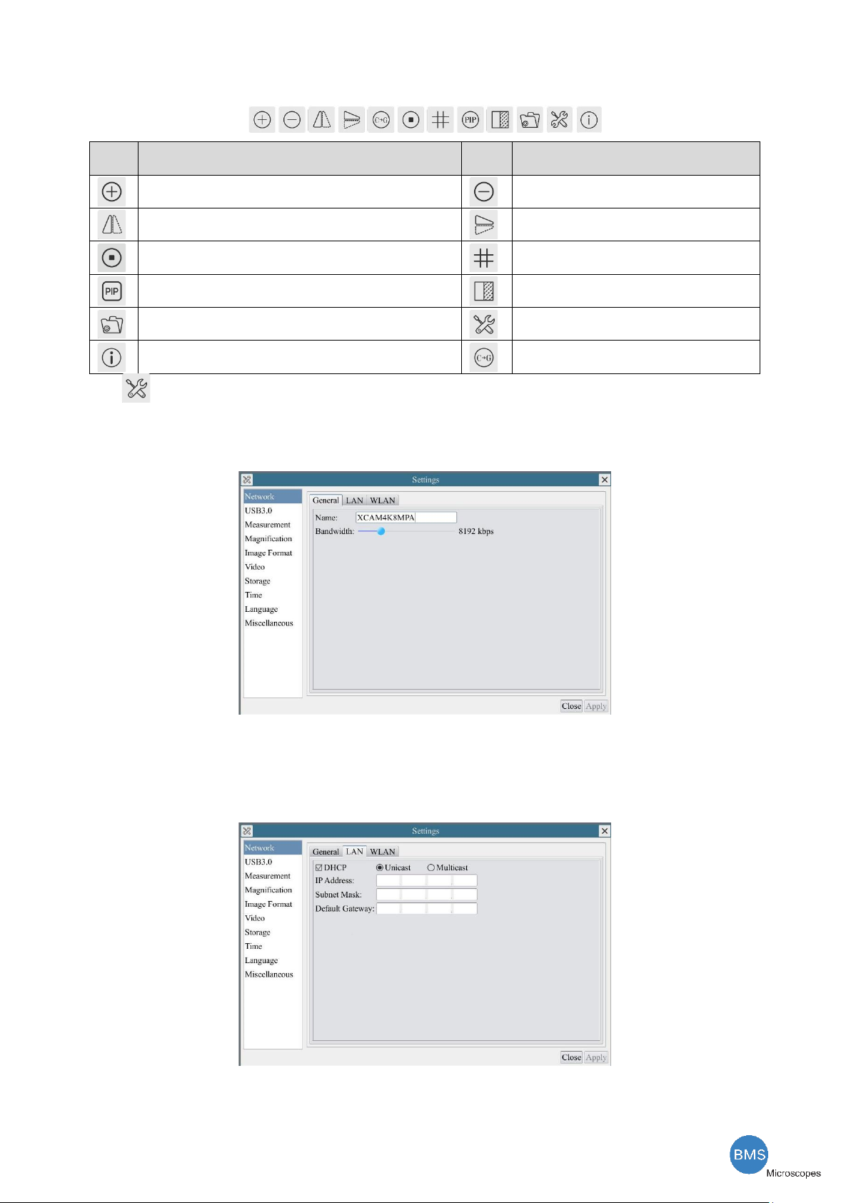
8.4 Icons and functions of the Synthesis Camera Control Toolbar at the bottom of the video window
Icon
Function
Icon
Function
Zoom In the Video Window
Zoom Out the Video Window
Horizontal Flip
Vertical Flip
Video Freeze
Display Cross Line
Picture in Picture
Compare Image with the Current Video
Browse Images and Videos in the SD Card
Settings
Check the Version of Onboard BMS
Color/gray
The Setting function is relatively more complicated than the other functions. Here are more informations
about it:
8.4.1 Setting>Network>General
Figure 8-3 Comprehensive Network Settings Page
Name
The current camera name recognized as the network name
Bandwidth
The encoding bandwidth for the video transmission stream. The larger the bandwidth, the higher quality the video.
8.4.2 Setting>Network>LAN
Figure 8-4 Comprehensive Network LAN Settings Page

The HDMI 4K Series Camera Help Manual
18 / 29
DHCP
Dynamic host control protocol allows DHCP server to automatically assign IP information to the camera. Only in Sec 6.4
LAN networking this item should be checked, so that cameras can automatically get IP information from routers/switches to
facilitate networking operation;
Unicast/Multicast
By default, unicast function is used. Only in Sec 6.4 networking environment, when the router/switch has multicast function,
camera can switch to multicast mode, which can save the network bandwidth consumed by the camera and facilitate the
connection of more cameras in the same network;
IP Address
Every machine on a network has a unique identifier. Just as you would address a letter to send in the mail, computers use the
unique identifier to send data to specific computers on a network. Most networks today, including all computers on the
Internet, use the TCP/IP protocol as the standard for how to communicate on the network. In the TCP/IP protocol, the unique
identifier for a computer is called IP address.
There are two standards for IP address: IP Version 4 (IPv4) and IP Version 6 (IPv6). All computers with IP addresses have an
IPv4 address, and many are starting to use the new IPv6 address system as well.
Users must manually configure their IP addresses on the camera side and computer side. The IP
addresses set on the camera side and computer side should be in the same network segment.
The specific settings are shown
Figure 8-5. It's usually a private address. Private address is a non-registered address used exclusively within an organization.
The internal private addresses retained are listed below: Class A 10.0.0-10.255.255; Class B 172.16.0-172.31.255.255; Class
C 192.168.0-192.168.255.255. The suggested IP address is Class C.
Subnet Mask
Subnet Mask is used to distinguish network domain from host domain in 32-bit IP address;
Default Getway
A default gateway allows computers on a network to communicate with computers on another network. Without it, the
network is isolated from the outside. Basically, computers send data that is bound for other networks (one that does not
belong to its local IP range) through the default gateway;
Network administrators configure the computer’s routing capability with an IP range's starting address as the default gateway
and point all clients to that IP address.
Uncheck the DHCP and select the Unicast item, user still need to set the IP address, Subnet mask and Default
Gateway as shown below:
Figure 8-5 Manual DHCP and Unicast
Uncheck the DHCP and select the Multicast item, user still need to set the IP address, Subnet Mask and Default
Gateway as shown below:
Figure 8-6 Manual DHCP and Multicast
Table of contents


