BMV FarmScan L60 User manual

FarmScan® L60
The Versatile Ultrasound machine
for small and large animal scanning
User Guide
BMV1956-C English
P/N No.: MX30-02463
Release date: June
We specialize because you do.

2
Thank you for choosing our FarmScan® for On-farm Animal fertility and pregnancy
detection.
We, BMV TECHNOLOGY CO., LIMITED are great provider of animal diagnostic imaging
equipment. We are focused on large pregnancy ultrasound scanning suitable for breeders of
most livestock, including beef cattle, dairy cattle, water buffalo, deer, swine, sheep, goats, llamas,
ponies, etc. We always focused on supplying the best ultrasound products and services to our
customers, distributors and suppliers.
Our Objectives are:
1) To supply the best quality ultrasound products and steady services to our users;
2) To work hand in hand with farm industry partners to promote ultrasound device worldwide.
BMV TECHNOLOGY CO., LIMITED
Tel: +86-755-26564580 /Fax: (00852) 2851 0669
www.bmv.cc
Email: info@bmv.cc
If you have comments about the documentation, please write to us at the email address above.
We would like to hear from you.
BMV Technology Customer Satisfaction
Input from our customers helps us improve our products and services. As part of our customer
satisfaction program, we contact a sample of our customers a few months after they receive their
orders. If you receive an email message from us asking for your feedback, we hope you will be
willing to answer some questions about your experience buying and using our products. Your
options are important to us. You are of course always welcome to contact us via your BMV
Technology representative or by contacting us directly.
Service Email: service@bmv.cc
All rights reserved. P12529‐22 06/2015
©2009~2015 BMV TECHNOLOGY CO., LIMITED
Information in this document may be subject to change without notice.

3
Content
Chapter 1: Getting Started.................................................................................................................................. 11
1.1 About the system....................................................................................................................................11
1.2 EMC statement:....................................................................................................................................... 12
1.3 Range of application..............................................................................................................................13
1.4 Preparing the system.............................................................................................................................13
Operating environmental requirements.........................................................................................13
Unpacking inspection...........................................................................................................................14
Compartments and connectors.........................................................................................................14
Installing and disassembling battery...............................................................................................15
1.5 Power Supply........................................................................................................................................... 15
1.6 Battery Charging.....................................................................................................................................15
1)Charging through direct with battery..........................................................................................16
2)Charging through main unit...........................................................................................................16
3)Charging through auto-charger.................................................................................................... 16
1.7 Battery Operation................................................................................................................................... 17
Charter 2: Operation Sequence......................................................................................................................... 18
2.1 Screen Display..........................................................................................................................................18
2.2 Keyboard Functions................................................................................................................................18
2.3 Power on....................................................................................................................................................22
2.4 Diagnose................................................................................................................................................... 22
2.5 Modify Image Parameters....................................................................................................................23
2.5.1 Frequency Setting....................................................................................................................... 23
2.5.2 Focus settings...............................................................................................................................23
2.5.3 Frame correlation settings........................................................................................................23
2.5.4 Image Smoothen......................................................................................................................... 24
2.5.5 Gamma correction...................................................................................................................... 24
2.5.6 Gain Setting.................................................................................................................................. 24
2.5.7 Modify Brightness and Contrast.............................................................................................24
2.5.8 Probe Setting................................................................................................................................24
2.6 Note............................................................................................................................................................ 25
2.7 Function Introduction............................................................................................................................28
2.7.1 Cineloop playback.......................................................................................................................28
2.7.2 Image Storage.............................................................................................................................. 29
2.7.3 Pick out Image............................................................................................................................. 29
2.7.4 Image up/down flip.................................................................................................................... 30
2.7.5 Image left/right flip.................................................................................................................... 30
2.7.6 Color................................................................................................................................................30

4
2.7.7 Measure of perimeter, area and volume.............................................................................. 31
2.7.8 Statistics of Histogram...............................................................................................................34
2.7.9 Erase image storage................................................................................................................... 35
2.7.10 Output format of video...........................................................................................................35
2.7.11 Restore factory settings.......................................................................................................... 35
2.8 Distance measuring................................................................................................................................35
2.9 Volume Measuring................................................................................................................................. 36
2.10 Heart Rate Measuring(Only in“B/M”and “M” Modes)................................................38
2.11 OB calculation....................................................................................................................................... 38
2.12 Image Printing.......................................................................................................................................44
2.13 Image upload to computer............................................................................................................... 44
2.14 Power Off................................................................................................................................................ 44
Chapter 3 Troubleshooting and Maintenance..............................................................................................45
3.1 Troubleshooting...................................................................................................................................... 45
3.2 Service life.................................................................................................................................................45
3.3 Check.......................................................................................................................................................... 45
3.4 Main unit maintenance......................................................................................................................... 46
3.5 Probe maintenance................................................................................................................................ 46
3.6 Cleansing...................................................................................................................................................47
3.7 Correct usage of probe......................................................................................................................... 48
3.8 Battery information................................................................................................................................48
3.9 Instrument test and calibration.......................................................................................................... 50
3.10 Maintenance of THIS EQUIPMENT Veterinary Ultrasound Scanner......................................50
Basic content of maintenance............................................................................................................50
Basic methods of maintenance......................................................................................................... 50
Notes of maintenance..........................................................................................................................51
Appendix A Acoustic output reporting table................................................................................................52
Appendix B Obstetrics..........................................................................................................................................55

1
Regulation
Declaration of Conformity(Europe only)
(FarmScan® M30,FarmScan® M50,FarmScan® L60 ,FarmScan® L70)
BMV Technology Co., Ltd
declare that this product is in compliance with the essential requirements of Directives
93/42/EEC As amended by 2007/47/EC:
ENISO14971:2009
ISO10993-1:2009
EC60601-2-37:2008EN1041:1998
EN980:2008
EN62304:2006
EN60601-1:1988+A1:1991+A2:1995
IEC60601-1-2: 2007I
EN60601-1-4:1996+A1:1999
The declaration of Conformity(DoC) is on our website.
Execution Standard(Safety)
Standard Number
Standard Name
EN60601-1
Medical Electronic Device, Part I:General safety requirements
IEC60601-1-2:2007
Medical Electronic Device, Part I to II: General Safety Requirement --
Parallel Standard: Requirement and Testing of Electromagnetism
Compatibility
IEC60601-1-4:2000
Medical Electronic Device, Section I to IV: A Program-controlled
Medical Electronic System
IEC60601-2-37
Medical Electronic Device, Specialized Safety Requirements for
Medical Ultrasound Diagnosis and Custodial Care Facility
If you need our help, please contact info@bmv.cc

2
Introduction
This Veterinary Ultrasound Systems FarmScan® L60 User Guide provides information on
preparing and using the FarmScan® L60 ultrasound equipment and on cleaning and disinfecting
the system and transducers. It also provides system specifications, and safety information.
The user guide is for a reader familiar with ultrasound techniques. It does not provide training in
solography or on-farm practices. Before using the system, you must have ultrasound training.
See the applicable BMV Technology Co., Ltd accessory user guide for information on using
accessories and peripherals. See the manufacturer’s instructions for specific information about
peripherals.
Customer comments
Questions and comments are encouraged.
BMV Technology Co., Ltd is interested in your feedback regarding the system and the user guide.
You can call the nearest manufacturer’s representative. You can also e‐mail BMV Technology
Co., Ltd at info@bmv.cc .
Conventions
The user guide follows these conventions:
WARNING
AWARNING label applies to information that may cause severe personal injury, death or
actual property loss if neglected.
CAUTION
ACAUTION applies to information that may cause mild personal injury or property loss if
neglected.
NOTE
ANOTE label applies to information on installation, operation or maintenance, which is very
important but poses no risk potential.
Numbered steps in procedures must be performed in order.
Items in bulleted lists do not require a sequence.

3
Matters need Attention
To ensure operational safety and long-term stable equipment performance, please read this
operation manual closely and understand the device functions, operation and maintenance at all
points before operating the device, especially contents of "Warning", "Caution" and "Note".
Mis-operation or inobservance of the instructions given by manufacturer or its agents may result
in device damage or personal injury.
The following convention works through this manual to lay special emphasis on some
information.
"Warning": Stands for neglect of it will cause severe personal injury, death or realized property
loss.
"Caution": Stands for neglect of it will cause slight personal injury or property damage.
"Note": to remind user of installation, operation or maintenance information. These information
is very significant but with no risk. Any warning against dangers shall not be contained in NOTE.
Safety labels
Device labels explanation:
Attention!consult accompanying
documents
==
Switch on the main electrical
supply
Switch off the main electrical
supply
AV
Signal output
USB port
IPX7
Protected against the effects of
immersion
ClassⅡ device
Electronics electrical equipment
separate collection
Packing and transportation labels explanation:
Handle with care
Temperature limit
Upwards
Limited layers of stowage
Protect against wetness
Protect against heat
Device safety classification:
●According to the degree of safety of application in the presence of a flammable anaesthetic
mixture with air or with oxygen or nitrous oxide:

4
THIS EQUIPMENT cannot be used in situation of mixture of inflammable anaesthesia gas and air
or nitrous oxide.
●Classify as per work system:
THIS EQUIPMENT is continuous operation device.
●Classify as per harmful liquid leakage:
The main unit of THIS EQUIPMENT is conventional device; the probe is a device of resistance to
flooding.
●Classify according to shockproof type:
THIS EQUIPMENT is GroupⅡ device powered by external adapter.
●Classify according to shockproof level:
THIS EQUIPMENT is Type B Applied part
Statement
Information in this document is not annotated to change. The manufacture shall not state nor
observe any warranty basing on this point, and definitely give up any implied warranty basing on
any special purpose of selling or making benefit.
We preserve the right of revision on this document without still further notice.
Some pictures in this manual, which are schematic diagrams for indication only, may disaccord
with the real object, and then the real object should be regarded as the final.
Manufacturer's warranty
Our company assumes the responsibility for device security, reliability and performance only
under the preconditions that the disassembly, assembly and maintenance of the device are all
performed by its assigned professional and the device is used strictly in compliance with the
operation manual.
We provides 2 years after-service for FarmScan® L60, specifically, machines for 2 years while
probes for 12 months, calculated from shipping of factory ,and that the new system is free from
any fault in material or workmanship
If unfortunately broken (non-man-made)during first 12 months, we will offer free shipping and

5
free repair. But the remaining years of machine, the manufacturer will offer free repair service , all
under BMV Pro-Support service, and the end-user buyers should pay for the any fees back and
return.
This guarantee is only available for failures occurred when the device is operated in compliance
with the operation manual. And the guaranteed device can only be used in the prescribed range
given in manual.
This guarantee excludes losses or damages caused by external reasons such as accidents, misuse,
abuse, falls, modification or alteration to any part or component of the system or abuse and
refitting the device.
Surface damage is not included in the free repair or replacement range. Battery replacement,
training material supply, etc. are not free, either.
Our company shall not be responsible for damages caused by other devices or arbitrary
connection to other devices.
Our company shall not be responsible for losses, damages or injuries caused by delayed service
request.
When there is problem with the products, please contact our company and explain the device
model, serial number, date of purchase and the problem.
BMV Pro-Support service:
service@bmv.cc
Responsibility of the manufacturer
BMV takes responsibilities for safety, reliability and performance of the system under only the
following conditions:
Installation, expansion, readjustment, upgrade and repair are all conducted by personnel
authorized by BMV TECHNOLOGY CO., LIMITED
Relevant electrical systems conform to applicable national standards.
The system is used according to conditions and requirements in the instruction.
User notice
To ensure operation safety and long-term stable performance of the system, it’s

6
strongly recommended reading this manual to get a full knowledge on the function,
operation and maintenance before operating the system.
Pay special attention to contents of “Warning”, “Caution” and “Notice” in this
manual.
BMV takes no responsibility for any damage or harm caused by incorrect operation or
maintenance inconsistent with instructions of BMV or its agent thereof.
Following messages which can be read throughout this manual are supposed to be paid
special attention to.
FAQS for BMV PRO-SUPPORT SERVICE
BMV Technology's Brand mark is a trusted brand worldwide .We are passionate about ensuring
that our customers obtain the best from our products. Wherever you are, you can rely on
receiving the best customer service.
How we care and maintenance FarmScan® ?
• Wipe display gently with a lint free cloth. Cleaning cloth and cleaners for glasses/sunglasses
work well. Care should be taken not to scratch the screen.
• Video cap or goggle must be plugged in at all times during cleaning so water does not enter
the scanner.
• Store in a dry environment. Corrosion will occur if stored damp.
How do I get my ultrasound machine repaired ?Where do I ship my ultrasound equipment
for repair?
Call your distributor or head office to arrange repair. Find service@bmv.cc
How should I ship my ultrasound equipment for repair?
We recommend shipping via air freight company (FEDEX/DHL/UPS/EMS), that provides you with
a tracking number. We do not typically insure packages; that is at your discretion.
And you should select freight company at lowest price.
What are the warranty terms and conditions?
We have two warranties for main unit and one warranty for probes.
Highlights
• The warranty covers defects in the manufacturing of the goods.

7
• The warranty does not cover accidental damage of the goods while in storage or use.
• BMV will ensure only authentic/original BMV brand parts are used when servicing
equipment.
• Failure to use authentic/original BMV parts on or within equipment by customer invalidates
warranty.
• All BMV ultrasound scanners and accessories are delivered, serviced and maintained by our
authorized service center or head office. Staffed by our experienced service personnel ensuring
dedicated customer focus and quick turnaround at all times.
How do I know if my product is still under warranty?
Your equipment is typically covered for 2 years, or as noted on your invoice. You can also call
distributor in your country or email to BMV service center and check your account for a warranty
expiration date. In regards to repairs, we cannot determine if an item is under warranty until it is
sent in and checked by our service department.
How often are there upgrades?
There is not a set schedule for upgrades. Upgrades are completed when your item is in for
service. Most upgrades just enhance the functionality of the unit. If an upgrade is needed
because of a serious problem we will contact those customers that need the upgrade individually
and get the units in for an upgrade immediately.
Can I leave my ultrasound machine outside in the cold?
While in use your ultrasound machine is built to stand up to extreme weather conditions,
including those below 0° days. However, your ultrasound is a piece of electronic equipment and
should be treated as such. Your machine should always be stored in a room temperature
environment when not in use.
Do you have a product to send in for repair?
Our dedicated service specialists and fast turn-around time will have your product back to you
faster than you expect.
HOW TO SEND IN
Follow these easy steps to send in your equipment for repair.
1. Contact us
To contact the Customer Service Department of Manufacturer first. Please provide the model
number, serial number, and a brief description of the reason for return. It is for the purpose to
obtain a Return Materials Authorization (RMA) number.

8
This (RMA) number must appear on the outside of the shipping container. Any returned
shipments will not be accepted if the number is not clearly visible.
2. Pack it
In order to complete your ultrasound scanner repairs in a timely manner please include a
document in the box with your name, business name, contact telephone number and a brief
description of the problem(s) you have been experiencing.
To avoid delays in your service, we recommend only sending in your ultrasound scanner which is
broken.
Be sure to pack your equipment well to prevent damage in shipment. The recommended
padding/cushion amount is two inches of padding between the object you are shipping and the
sides of the box.
3. Ship it
We recommend shipping via an air freight company that provides you with a tracking number.
We typically do not insure packages; that is at your discretion.
4. Repair returned
We aim to complete your repair and return your system as soon as possible. As soon as we
receive your equipment in our BMV service center, 99% of our repairs are completed and shipped
back within 48 hours. This lessens the need for a loan ultrasound machine.
General tips for device operation
In operation
1.Heat radiation holes are strictly prohibited to be covered.
2.After closedown, do not switch on the device within 2 - 3 minutes.
3.On scanning, if any abnormal case is found, stop scanning immediately and shut down the
device.
After operation
1. Power off the device.
2. Pull out the plug from power supply socket instead of pulling the cable.
3. Clean off the couplant on the probe with soft medical sterilized cotton ball.

9
General Safety Message
Safety of the operator and patients and reliability of the device are taken into consideration
during designing and producing, the following safety precaution must be implemented:
1. The device shall be operated by qualified operating staff or under their instructions.
2. Do not open the device and change the parameters without permission. If necessary, please
turn to for Our company or its authorized agent for service.
3. The device has already been regulated into its optimal performance. Do not adjust any preset
control or switch unless operate as per instructions in the manual.
4. If there is device failure, please shut down the device at once and contact for Our company or
their authorized agent.
5. If it is needed to connect the device with other company’s' electronic or mechanical devices,
please contact Our company before connection.
6. Device operation, storage and transportation environment
Environmental requirements on normal operation:
a) Environment temperature range: +5℃~ +40℃
b) Relative humidity range: 30%~80%
c) Atmosphere pressure range: 700hPa~1060hPa
Environment requirements on device storage and transportation:
a) Environment temperature range: -5℃~+40℃
b) Relative humidity range: <80%(20℃)
7. Do not hit the fragile TFT-LCD display. If it cracks, deal carefully with it in case the liquid crystal
gets into eyes or mouths.
8. Must not hit the inner rechargeable lithium battery nor throw it into fire in case it trigger an
explosion;Do not short circuit the battery output electrodes in case the battery be damaged;
and please use the original binding charger to charge the battery. Moreover, because used
battery will cause environment pollution, please handle the battery correctly for recovery
processing.
9. Must not disassemble the power supply adapter. If failures happen, it should be handled by
the professional; the charging output can only be used for charging the battery of the device,
any improper use on other battery may cause explosion, fire and other unexpected hazards.

10
10. Must not short circuit the output of the adapter , a long term short circuit shall result in
adapter damage.
11. Please use standard power cord as the input line of the network power supply for the adapter
to reduce risk.
12. Our company shall not take any responsibility for any risk resulted from propelled /
unauthorized re-fitment by the users.
13.To disconnect the device from the power supply network by unplug the adapter from the
power supply network.
14.Ultrasound might cause hazard on human body so long time radiation should be avoided.
Refer to appendix A for sound output parameters.

11
Chapter 1: Getting Started
1.1 About the system
Thanks to six(6) different probes , I.F.R™ introducer and I-Scan® video glasses, FarmScan® L60
can perform all veterinarian applications and even more easily. FarmScan® L60, featuring
premium image quality, considerate design for comfortable, fast and reliable detection of
pregnancy and gynecological diagnosis in difficult field conditions on a daily basis.
(Manufacturer: BMV Technology Co., Ltd www.bmv.cc )
• Fast and reliable detection of pregnancy from 28th day on cows, 13th on mares, 25th on
sheep and goats ,18th on pigs (pregnancy control, ovarian examinations, postpartum
diagnosis, …)
• Foetal sexing on cows , mares, sheep and goats
• Back fat measurements on pigs, cows and sheep
• Teats’control, genital bull tract exams, …
We’re the only one in market, because of:
• 32 digital channels and 128 elements probe
• Video output, support I-Scan® video glasses eases your job and gets you focused (optional)
• I.F.R™ introducer engineered to lessen fatigue and stress by allowing arm-free scanning, use
in a variety of reproductive diagnostic procedures.( optional, compatible with the Rectal convex
and Rectal Linear transducers)
Advance Features:
• Only weight 0.6 kg;
• Excellent imaging quality and ergonomic design;
• Provides versatile solutions with the greatest ease of use for all veterinarian applications –
bovine , equine, swine, ovine , Lama and small ruminants;
• 5.8 inch WVGA LCD monitor, wide viewing angle, LCD monitor can turn off when use I-Scan®
Video Goggle
• 4.5~5.5 hours Li-ion battery for operating;
• support USB 2.0 for ultrasound station to transfer images and video to your computer,
450~550-frame cine loop insider;
• Support leather sheath, designed to be resistant to extremely harsh farm conditions;
• Software & Report for reproductive system, and measurement for distance, area,
circumference, volume, angel, heart rate;
• Uses the 3rd generation innovative navigation, direct access keys and user buttons for fast,
12
single handed menu selection and setting changes;
Basic steps
1 Attach a transducer.
2 Turn the system on.
3 Tap Patient, and complete the animal ID information form.
4 Tap Mode and select an imaging mode.
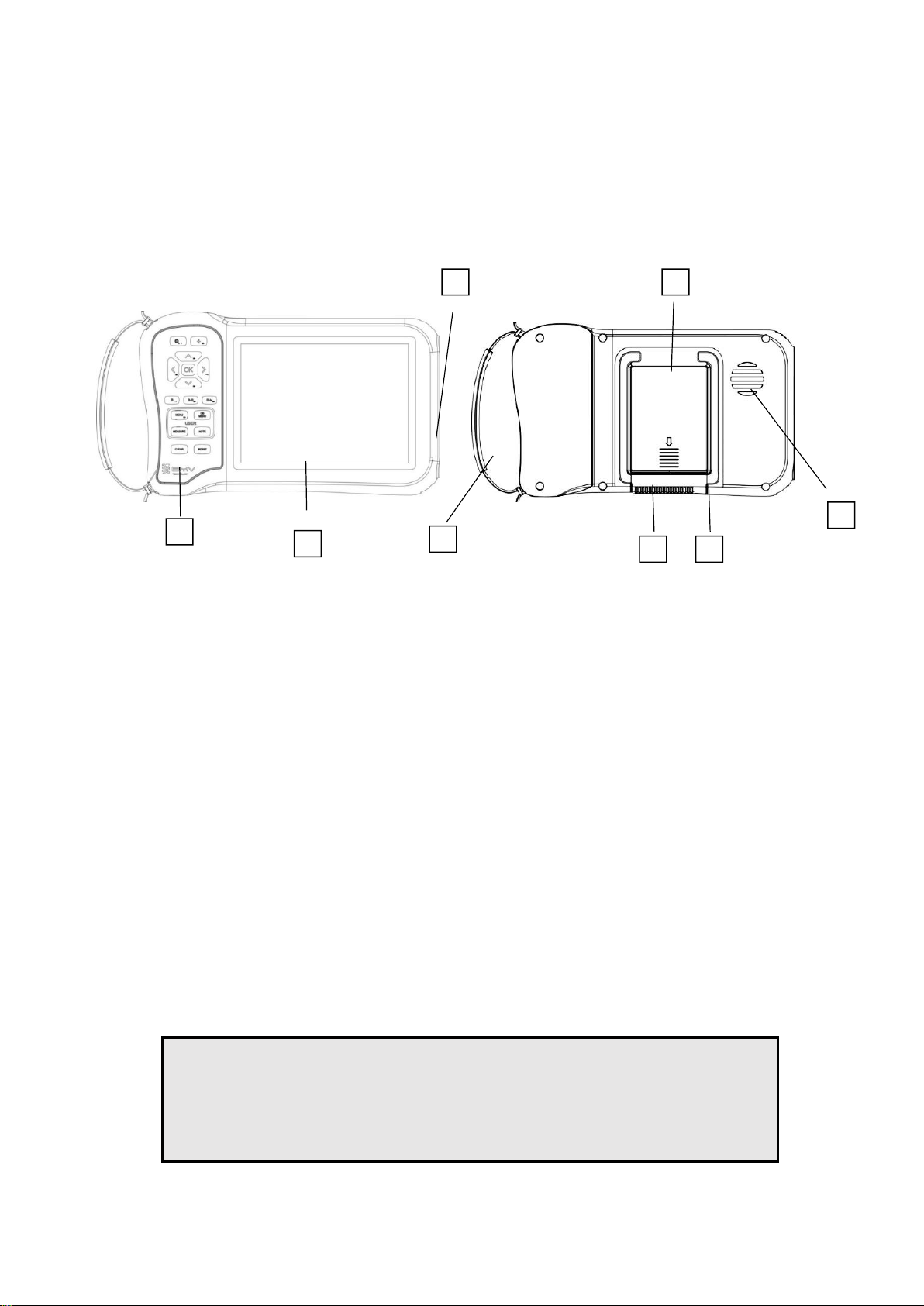
Figure 1 System front (top) and back (bottom)
1. Menu
2. Screen
3. Power switch, Probe connector , USB ports (on side)
4. Handle
5. Kickstand
6. Cool Fan Out
7. Battery compartment
8. Cool Fan In
1.2 EMC statement:
FarmScan® L60 can't affect the basic performance of radio service and other equipment, and can
work well in the expected and declared electromagnetic environments.
Warning:
Working in intense electromagnetic environment, its images may be
interfered and the diagnoses may be affected. By this time, stop
operating to avoid misdiagnosis. Reuse after the electromagnetic
interference is removed.
1
2
4
5
6
7
8
3

13
Warning:
Working when the device is overlapped with other devices or close to
others might cause unexpected EMC problems; If they have to be put
together, please check every one to ensure no one is affected by
unexpected EM coupling.
Warning:
Replacement of parts that not according with specs or connection to
other devices might cause unexpected EMC problems. The possibility of
unexpected EM coupling effect should be testifies carefully.
The device is comprised of 2 main parts:
1. Casing with the screen and keyboard
2. Ultrasound probe(s) integrated with the scanner
The probe is very important part of the scanner, because of its sensitive mechanism. it is
important to be careful and protect the probe from falling or hitting.
1.3 Range of application
Suitable for all veterinary applications –bovine beef, bovine dairy, Lama and small ruminants,
swine, ovine; pets such as dogs and cats.
1.4 Preparing the system
Operating environmental requirements
1. Environment temperature range:+5℃~+40℃
2. Relative humidity range:30%~75%
3. Atmosphere pressure range:700hPa~1060hPa
When using, avoid strenuous vibration, keep it away from devices with high field, intense
magnetic field or high voltage; avoid strong sunlight blazing down on the display; keep the
device well-ventilated, moisture proof and dustproof.
THE CONSTRUCTION OF THE SCANNER

14
Unpacking inspection
After unpacking, check the device according to "Packing List" and install it according to
requirements and methods described in "Installation" after affirm that there is no shipping
damage.
Warning
If there is breakage at unpacking check, it is banned to use the device to
ensure security.
Compartments and connectors
First, Connection between probe and main unit
The probe jack lies in the top of the right side of the equipment. There is only one plug jack
which is also compatible for those optional probes (refer to figure 1).
Picture 1. Probe connection sketch
Dismounting is the reverse process of installation.
Picture 2. Disassemble probes
Warning:
Avoid by all means unplugging or plugging the probe connector at state of log
on in case the probe and main unit be damaged.
Once the probe is connected with the main unit, do not unplug nor plug it at
discretion in case poor contact happen.
Warning:
Must not touch the contact pin in the probe connector.

15
Warning:
The probe should be protected from felling off or crashing and the manufacturer
assumes no responsibility for this kind of hazard.
Warning:
Please handle the device carefully.
Installing and disassembling battery
Install battery: Set the battery into the battery slot and move the battery release key on its back
to top till the battery is inserted completely and then release the key (refer to Picture 2-3).
1.5 Power Supply
The device provides two automatic switch-over modes to supply power: adapter and built-in
battery.
Installing or removing the battery
WARNING:
To avoid injury to the operator and to prevent
damage to the ultrasound system, inspect the
battery for leaks prior to installing.
To avoid data loss and to conduct a safe system
shutdown, always keep a battery in the system.
1.6 Battery Charging
When the main unit displays the battery in the empty status in the right top corner of the display
screen, it indicates that the batter should be charged. The battery should be charged via the
charging adapter cable.
Using AC power and charging the battery
The battery charges when the system is
connected to the AC power supply. A fully
discharged battery recharges in less than three
hours.
The system can run on AC power and charge the
battery if AC power is connected to the system.

16
The system can run on battery power for up to
four hours, depending on the imaging mode and
the display brightness. When running on battery
power, the system may not restart if the battery is
low. To continue, connect the system to AC
power.
1)Charging through direct with battery
1. Take out the battery from the main unit or take out the spare battery.
2. Connect the round end of the adaptive line to the " " terminal of the adapter, and the
flat end to the charging terminal of the battery.
3. Connect power cord of " " of the adapter to the AC EPS.
4. When the " " indicator light on the adapter turns into red, the battery is in charging;
when the " " indicator light turns into green, the battery is fully charged.
2)Charging through main unit
Direct contact with the FarmScan® L60 main unit.
3)Charging through auto-charger
1. Take out the battery from the main unit or take out the spare battery.
2. Connect the flat end marked with an arrow of the auto-charger to the charging terminal of the
battery.
3. Plug the other end of the auto-charger into the cigar lighter socket.
4. When the "Charging" indicator light on the adapter turns into red, the battery is in charging;
when the "Charging" indicator light turns into green, the battery is fully charged.
Tips:
1. The input voltage of the auto-charger is DC9~14V/1.5A.
2. The output voltage of the auto-charger is DC12.6V/1A.
3. The operations and storage environment are the same as those of the main unit.
Note
Table of contents


