EN/17
Auxiliary heating system
BMW 5 Series (E39) left-hand drive Saloon and touring
with M57 engine (diesel) from production date 03/99
Specialist knowledge required. For use within the
BMW dealer organisation only.
Installation time approx. 3 hours (3.5 hours for
touring model), depending on the condition of the
car and the equipment in it.
Please read the following notes
Read these installation instructions before
installing the auxiliary heating system.
Before disconnecting the battery and after
completing the installation work for the auxiliary
heating system, conduct a short test.
On cars without a high on-board computer or on-
board monitor, the auxiliary heating system can
only be operated using the remote control.
After the auxiliary heating system has been
installed, the system upgrade must be coded using
the DIS or MoDiC via the upgrade path.
All hose lines and cables are to be installed in such
a way that they cannot chafe or sag.
Ensure that all parts can move freely.
All hose clips are to be installed in such a way that
they cannot touch or chafe on electrical cables.
Some of the work required to install the auxiliary
heating system is not described in detail in these
installation instructions. In these cases proceed as
described in the relevant repair manual.
Deburr drilled holes, remove drill chippings and
complete the usual BMW anti-corrosion work.
Cavities into which you drill must be treated with
BMW-approved cavity preservative.
Refer to technical instructions and service
information.
The auxiliary heating system must not be
operated in enclosed areas such as garages or
workshops without a fume extraction system (not
even with the timer or using the remote control).
The auxiliary heating system must be switched off
at filling stations.
General notes on operation
The auxiliary heating systems consumes approx.
0.2 litres of fuel every 30 minutes. The exhaust
emissions generated by it are well below the
statutory exhaust emission limits as a result of its
uniform combustion process.
Operating the auxiliary heating system places extra
strain on the car’s battery. To avoid starting
problems and to stabilise the car’s electrical
system, we recommend that the car is driven
frequently during the cold weather when you use
the auxiliary heating system so that the battery
always has an adequate charge.
Recommendation: 30 minutes of auxiliary heating
system operation = 30 minutes of driving.
When the auxiliary heating system is not in use, the
heater is to be run for 10 minutes every four weeks
when the engine is cold to prevent starting
difficulties when you next need it (see also BMW
owner’s manual).
Tools and equipment required
MoDiC or DIS
Philips screwdriver
Straight slot screwdriver
1/2 inch torque wrench
1/2 inch reversible ratchet
1/2 inch extension
1/2 inch socket, size 17 mm
1/2 inch Torx socket, T50
1/4 inch reversible ratchet
1/4 inch extension
1/4 inch sockets, sizes 6, 7, 8, 10 and 13 mm
Set of ring spanners
Set of open-ended spanners
Angle drill
Twist drill bits, sizes 3.5 mm and 9.1 mm
Drill
Blind rivet nut pliers
Water-soluble pen
Tester for pressure testing the coolant system
Goggles
Universal knife
Angle cutter
Cable lamp
Hammer
Centrepunch
Tape measure
Table of contents
Section
1. Preparations
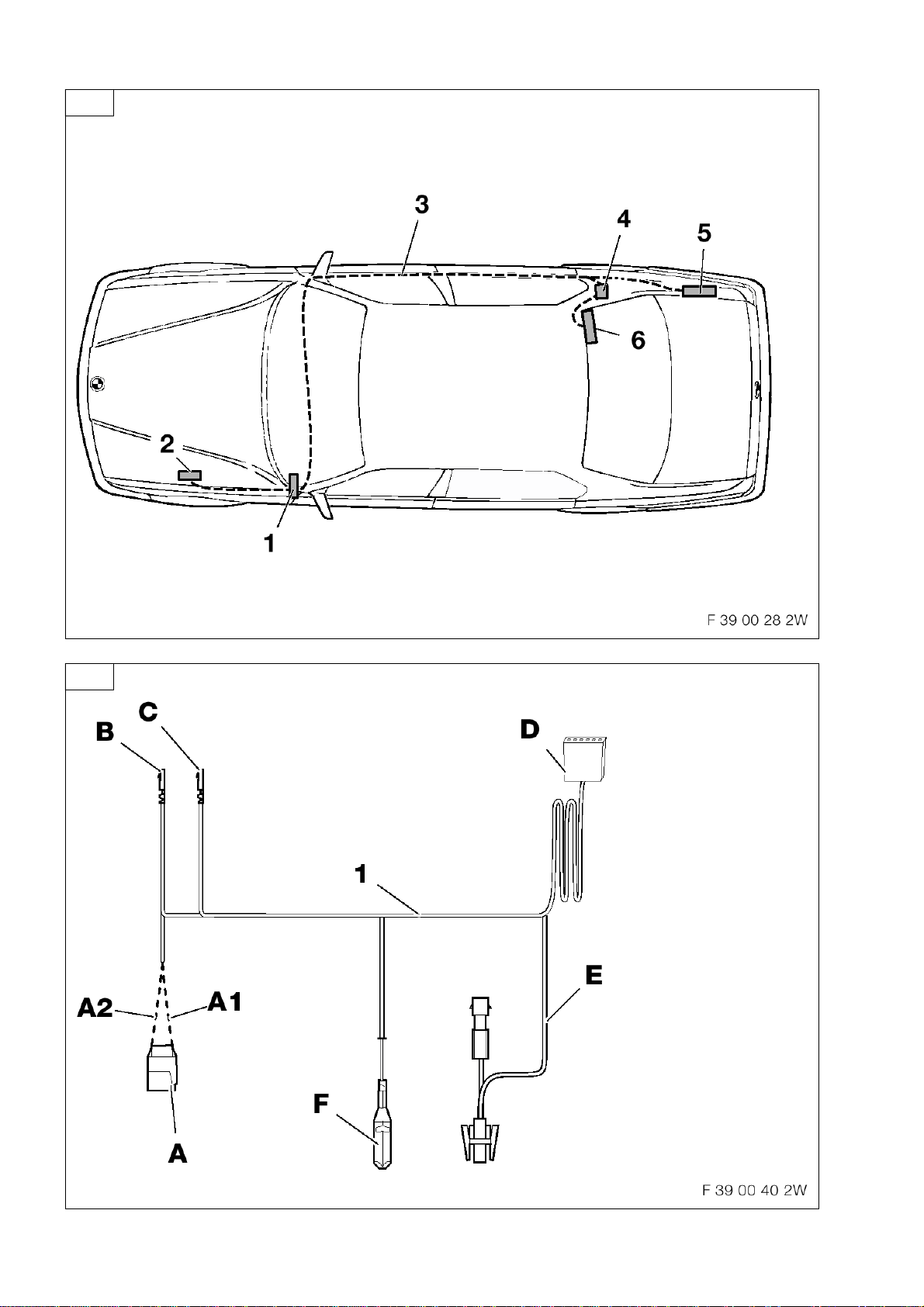
2. Installation and cabling diagram
3. Connection diagram for the auxiliary heating
system wiring harness
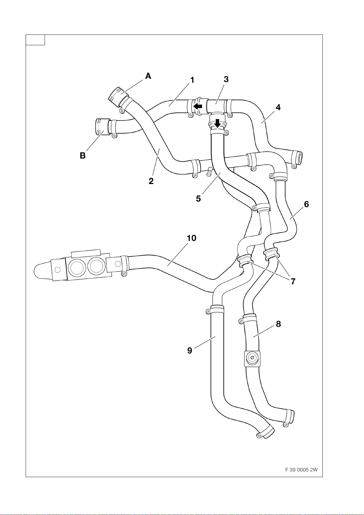
4. Overview of coolant lines
5. To install the auxiliary heating system wiring
harness
6. To install the components for the remote
control
7. To install the coolant lines
8. To code the controllers
9. To operate the auxiliary heating system using
the on-board computer or on-board monitor
10. To operate the auxiliary heating system with
Telestart
11. Servicing work for the auxiliary heating system
12. Concluding work
13. Legend / Circuit diagram for E39 M57
Telestart operating instructions