BMW F01 User manual

Revision Date:
F01 Audio Systems
Introduction ..................................................5
History ........................................................5
New eatures ..................................................5
SystemOverview .............................................6
GeneralInformation ............................................6
01/ 02 Audio/Bus System Overview . . . . . . . . . . . . . . . . . . . . . . . . . .7
Block Diagram of Head Unit CIC . . . . . . . . . . . . . . . . . . . . . . . . . . . . . . .9
CIC Head Unit Circuit Diagram . . . . . . . . . . . . . . . . . . . . . . . . . . . . . . .10
Hi i Speaker System Circuit Diagram . . . . . . . . . . . . . . . . . . . . . . . . .14
TOP-Hi i Speaker System Circuit Diagram . . . . . . . . . . . . . . . . . . . .16
Antenna System Circuit Diagram . . . . . . . . . . . . . . . . . . . . . . . . . . . . .18
USB/audio Interface Option Circuit Diagram . . . . . . . . . . . . . . . . . . .20
Smartphone Integration Option Circuit Diagram . . . . . . . . . . . . . . . .22
DVD Changer Circuit Diagram . . . . . . . . . . . . . . . . . . . . . . . . . . . . . . . .24
PrincipalsofOperation .......................................26
Comparison of CIC with CCC . . . . . . . . . . . . . . . . . . . . . . . . . . . . . . . . . .26
Display ......................................................29
Controller ....................................................30
CD/Multimedia ...............................................32
Storing Music Data on the HDD . . . . . . . . . . . . . . . . . . . . . . . . . . . . . .33
Rip unction ............................................34
Copying Data via the CD/DVD Drive . . . . . . . . . . . . . . . . . . . . . . . .35
CopyingDatafromtheUSB...............................36
ileSystem ................................................38
DataSaving(Backup)........................................39
MusicSearch...............................................40
Updating the (Gracenote®)Database .........................43
Radio ........................................................44
MStations ................................................44
AMStations................................................45
IBOC ......................................................46
SDARS ....................................................46
StoredStations ..........................................46
SettingsMenu ...............................................47
avoriteButtons ............................................48
Subject Page
Table of Contents
Initial Print Date: 01/09

SystemComponents .........................................49
CarInformationComputer(CIC).................................50
Advantages of the Car Information Computer . . . . . . . . . . . . . . . . . .53
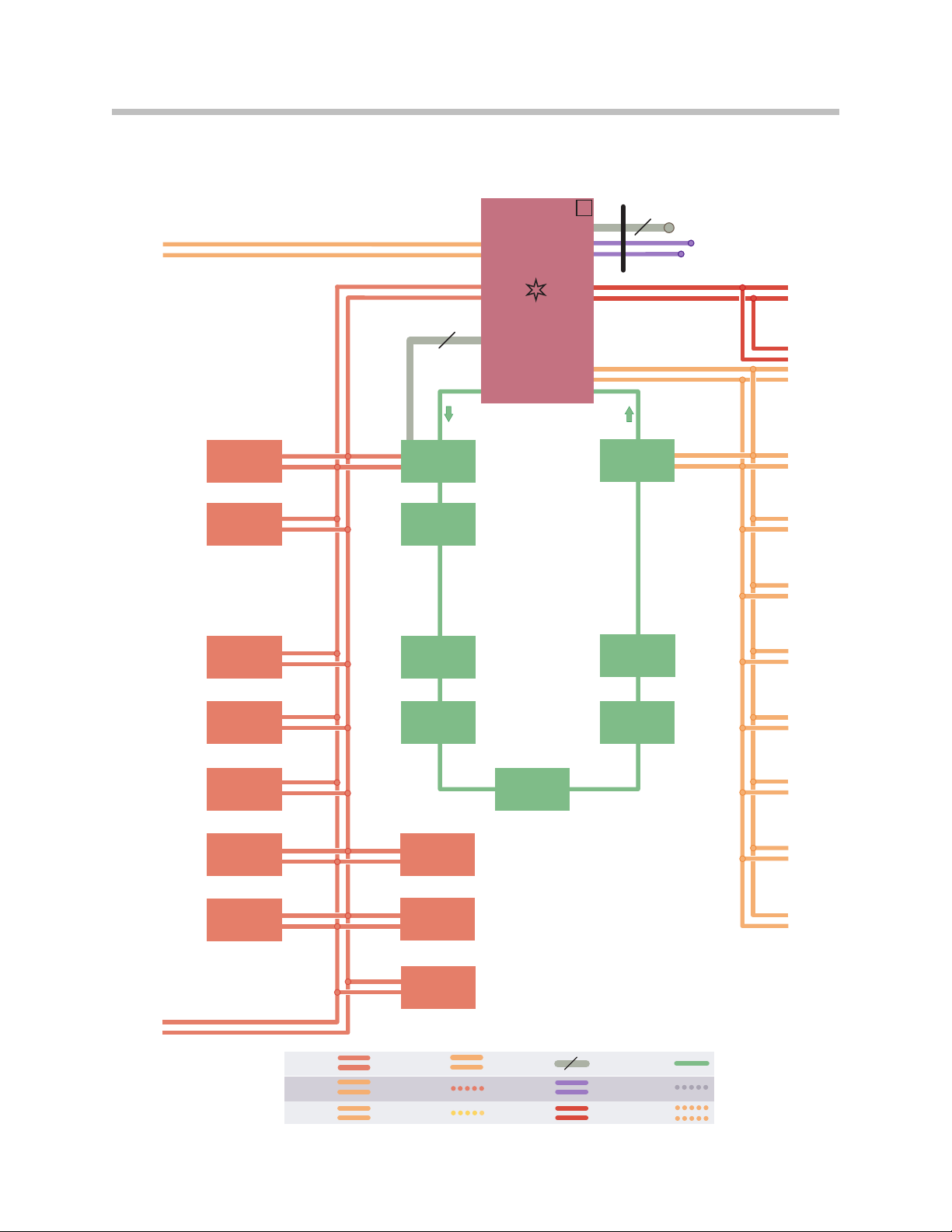
LVDS echnology .......................................55
8-wireLVDS................................................55
2-wireLVDS................................................55
ElectrostaticDischarge(ESD) ...................................56
Working on Electronic Components . . . . . . . . . . . . . . . . . . . . . . . . . . .57
CICComponents ..........................................58
Optical Drive (CD/DVD Player) . . . . . . . . . . . . . . . . . . . . . . . . . . . . .59
HardDiskDrive ..........................................60
FixedComponents ............................................61
Fan........................................................62
GPSReceiverModule .......................................63
YawRateSensor............................................64
GatewayProcessor..........................................64
Analog unerModules ......................................65
FMandAMStationList ..................................65
IBOCSystem/HDRadio .....................................66
CIC Application Board with Processors . . . . . . . . . . . . . . . . . . . . . . . .68
PowerBoard ...............................................68
AmplifiersandSpeakers .......................................69
HiFiSpeakerSystem ........................................71
HiFiAmplifier ...............................................72
op-HiFiSpeakerSystem....................................73
op-HiFiAmplifier ..........................................74
AntennaSystemOverview .....................................77
Antenna Diversity Module with Amplifier . . . . . . . . . . . . . . . . . . . . . . .79
FMAntennaDiversity .......................................80
Selection of the individual antennas (diversity function) . . . . . . .81
Selection of the various reception modes of the
antennadiversitymodule .................................81
AMDiversity ..............................................82
Remote Control Services (FBD) . . . . . . . . . . . . . . . . . . . . . . . . . . . . .82
FMRejectorCircuit .........................................82
HBLFilter .................................................83
AMRestrictor .............................................84
RoofAntenna...............................................85
SDARSSatellite uner .........................................86
ExternalAudioSources ........................................90
DVDChanger ..............................................90
USB/AudioInterface ........................................93
iPod®Connection .......................................95
“USB/audio interface” Components . . . . . . . . . . . . . . . . . . . . . . .96
USBHub ..................................................98
Subject Page

AudioJack ................................................99
SmartphoneIntegration .......................................100
Audio Data Control Line . . . . . . . . . . . . . . . . . . . . . . . . . . . . . . . . . . .102
ServiceInformation .........................................103
Unlocking the Service Menu Option . . . . . . . . . . . . . . . . . . . . . . . . . . . .103
Navigation ................................................104
Telephone and BMW Service . . . . . . . . . . . . . . . . . . . . . . . . . . . . . . .105
TV .......................................................106
Gracenote®...............................................107
ResettingtheCIC ............................................108
Programming ................................................108
Subject Page

Audio Systems
Model: F01/F02
Production: From Start of Production
After completion of this module you will be able to:
• Describe the Audio System on the 01/ 02
• Identify the components of the Audio System on the 01/ 02
• Describe the CIC system and its relation to the Audio System of the 01/ 02
• Identify the components of the CIC system
4
01 Audio Systems

History
With the launch of the E65, an optical bus (MOST) was used for the first time in a series
production vehicle for the purpose of transmitting digitized audio signals.
With the introduction of the E93 in 2007 a USB interface for external audio devices was
offered for the first time in BMW vehicles. The media can be accessed from the iDrive
and the audio data played through the vehicle speakers.
New Features
The CIC system is a further development of the previous CCC system. The CIC head
unit was installed for the first time on the BMW 1 Series and 3 Series in 2008.
The New BMW 7 Series, the 01/ 02 is equipped with an enhanced version of the
CIC system.
By storing data on a 80 GB hard disk, the new head unit provides many new functions
and options.
In the audio systems, this development is reflected by the new music collection function.
Music files can be converted (ripped) or copied for the music collection onto the hard
disk.
Storing the music on the CIC-dedicated hard disk allows fast access to these music
files at all times.
A selection of up to 3700 music files (12 GB) is possible.
A USB interface is provided in the glove compartment for import/export purposes
(data copy or data backup).
The digital radio systems IBOC tuner/decoder is now integrated in the CIC.
A common station list together with the analog systems provides added convenience.
An improved antenna system makes reception of the radio stations even more stable
and less prone to interference. An additional interference suppression filter enhances the
reception over long distances, particularly in the AM range.
A modified base plate makes it possible to connect to and play back music tracks stored
in the mobile phone with the Smartphone Integration option (6N ). This option is
currently available only with the iPhone®.
Music tracks stored in the mobile phone can now be easily accessed. Simple menu
navigation and playback of these music tracks can now be controlled via the iDrive.
Introduction
5
01 Audio Systems

General Information
The system overview of the 01/ 02 audio system begins with a general bus overview.
It shows the interconnection of all IKT components in the bus system network.
A block diagram of the Car Information Computer is also provided.
Particular reference is made to the individual levels within the CIC head unit:
• User interface
• Application software
• Hardware components
Detailed information can be found in the following pages on the individual
circuit diagrams:
• CIC Head unit circuit diagram
• Hi i speaker system circuit diagram
• TOP-Hi i speaker system circuit diagram
• Antenna system circuit diagram
• USB/audio interface circuit diagram
• Smartphone Integration circuit diagram
• DVD changer circuit diagram
Note: The Top HiFi System refers to the Premium-HiFi System.
System Overview
6
01 Audio Systems

F01/F02 Audio/Bus System Overview
MOST
Ethernet
PT-CAN
PT-CAN2
K-CAN
FlexRay Local-CAN
D-CAN
K-Bus
(protokoll) BSD
LIN-Bus
5
K-CAN2
5
PT-CAN
K-CAN
K-CAN2
5
IHKA
FKA
HUD
CID
FD FD2
TRSVC HiFi
VSW
CON
ULF-SBX
High
SDARS
TCU
TOP HiFi
DVD
CIC
KOMBI
ZGM
S
OBD
RSE Mid
7
01 Audio Systems

ey to abbreviations - bus overview
Index Explanation
CAS Car Access System
CIC Car Information Computer
CID Central information display
CON Controller
DVD DVD changer
FD Rear-seat display
FD2 Rear seat area display 2
HiFi Hi i amplifier
HKA Automatic A/C, rear seat compartment
HUD Head-Up Display
IHKA Automatic climate control
KOMBI Instrument cluster
OBD Diagnosis socket
RSE Rear Seat Entertainment
SDARS Satellite tuner
CU Telematics control unit
OP HIFI Top-Hi i system
SBX High UL Interface box “High” (Bluetooth telephone,
voice input and USB audio interface)
VSW Video switch
ZGM Central gateway module
Index Explanation
D-CAN Diagnosis CAN
K-CAN Body CAN
K-CAN 2 ast body CAN
MOS Media Orientated System Transport
P -CAN Powertrain CAN
P -CAN 2 Powertrain CAN 2
8
01 Audio Systems

Block Diagram of Head Unit CIC
Ind x Explanation Ind x Explanation
1Central Information Display (CID) 4Application software
2Car Information Computer 5Hardware and interfaces
3User interface application
9
01 Audio Systems

CIC Head Unit Circuit Diagram
10
01 Audio Systems

Index Explanation Index Explanation
1Central gateway module 12 Antenna amplifier with diversity
2Diagnosis interface 13 Rear power distribution box
3Dynamic stability control 14 SDARS satellite radio tuner
4Central information display 15 Steering column switch cluster
5Junction box electronics module with
power distribution box 16 Instrument cluster
6Car Information Computer LVDS Low voltage differential signalling
7USB port in glove compartment MOS Media Orientated System Transport
8Automatic climate control USB Universal serial bus
9AUX-In connection in center console (jack plug) FlexRay lexRay bus system
10 Controller K-CAN Body CAN
11 Roof antenna
11
01 Audio Systems

-CAN signals at the CIC control unit, that are not defined in the system circuit diagram:
In/Out Signal Source/sink Function
In Speed signal Wheel speed sensor > DSC
> ICM > ZGM > Speed-dependent volume control
In Terminal status CAS > ZGM > Terminal control
In Timer bus signal Instrument cluster > ZGM > Transfer of ambient conditions
In Control CON > ZGM > User interface control
In Kl. 58g Light switch > RM > ZGM Button lighting/instrument lighting
Out Rad_on signal > ZGM > Hi i amplifier Rad_on signal for Hi i amplifier
12
01 Audio Systems

MOST signals at the CIC control unit, that are not defined in the system circuit diagram:
In/Out Signal Source/sink Function
In Decoded audio signals DVD changer > Speed-dependent volume control
In Information DVD changer > Metadata (ID3 tags)
In Date, time, language Instrument cluster > ZGM > Transfer of ambient conditions
In Kl. 58g Light switch > RM > ZGM > Button lighting/instrument lighting
In Data, audio signal ULB-SBX > Data, audio signal, USB interface,
Center console
In Data, audio signal ULB-SBX > Data, audio signal, mobile phone
in snap-in adapter
Out Rad_on signal > Top-Hi i amplifier Rad_on activation signal for Top-
Hi i amplifier
Out Audio signals >Top-Hi i
Audio signals (subsequently con-
verted in Top-Hi i amplifier and
output to individual speakers)
13
01 Audio Systems

HiFi Speaker System Circuit Diagram
14
01 Audio Systems

Index Explanation Index Explanation
1Central gateway module 10 Rear power distribution box
2Mid-range speaker, front center 11 Hi i amplifier
3Tweeter, front center 12 Tweeter, rear window shelf, left
4Car Information Computer 13 Mid-range speaker, rear window shelf, left
5Tweeter, front right door 14 Woofer, under left front seat
6Mid-range speaker, front right door 15 Mid-range speaker, front left door
7Woofer, under right front seat 16 Tweeter, front left door
8Mid-range speaker, rear window shelf, right K-CAN Body CAN
9Tweeter, rear window shelf, right
15
01 Audio Systems

TOP-HiFi Speaker System Circuit Diagram
16
01 Audio Systems

Index Explanation Index Explanation
1Car Information Computer 12 Axial-flow fan, TOP-Hi i amplifier
2Tweeter, front center 13 Top-Hi i amplifier
3Mid-range speaker, front center 14 Mid-range speaker, rear window shelf, left
4Tweeter, front right door 15 Tweeter, rear window shelf, left
5Mid-range speaker, front right door 16 Tweeter, rear left door
6Woofer, under right front seat 17 Mid-range speaker, rear left door
7Mid-range speaker, rear right door 18 Woofer, under left front seat
8Tweeter, rear right door 19 Mid-range speaker, front left door
9Tweeter, rear window shelf, right 20 Tweeter, front left door
10 Mid-range speaker, rear window shelf, right MOS Media Orientated System Transport
11 Rear power distribution box
17
01 Audio Systems

Antenna System Circuit Diagram
18
01 Audio Systems

Index Explanation Index Explanation
1Central gateway module 13 Rejector circuit, rear window defogger_1
2ootwell module 14 Rear window with individual M/ AM antenna
3Car Access System 15 Rejector circuit, rear window defogger_2
4Automatic climate control 16 Rear power distribution box
5Car Information Computer 17 Rejector circuit, rear window
defogger for AM range
6Junction box electronics 18 Emergency call antenna (backup)
7Base plate of universal charging
and hands-free (Not for US) 19 Telematics control unit
8Bluetooth antenna 20 SDARS satellite tuner
9Roof antenna K-CAN Body CAN
10 Interference suppressor filter, rear brake light K-CAN 2 ast body CAN
11 Rear brake light LIN Local Interconnect Network
12 Antenna diversity
19
01 Audio Systems

USB/audio Interface Option Circuit Diagram
20
01 Audio Systems
This manual suits for next models
1
Table of contents
Other BMW Car Receiver manuals

BMW
BMW Z4 User manual

BMW
BMW Traffic Pro User manual

BMW
BMW E60 MY2007 User manual

BMW
BMW Radio and Information Systems User manual

BMW
BMW Business CD Car Radio User manual

BMW
BMW Intravee II User manual

BMW
BMW Business CD Car Radio User manual

BMW
BMW iDrive 6.0 User manual

BMW
BMW Bavaria C business RDS User manual

BMW
BMW Professional CD Radio User manual