Cc
Clarion
.
CATS
(Computer
Anti-Theft
.
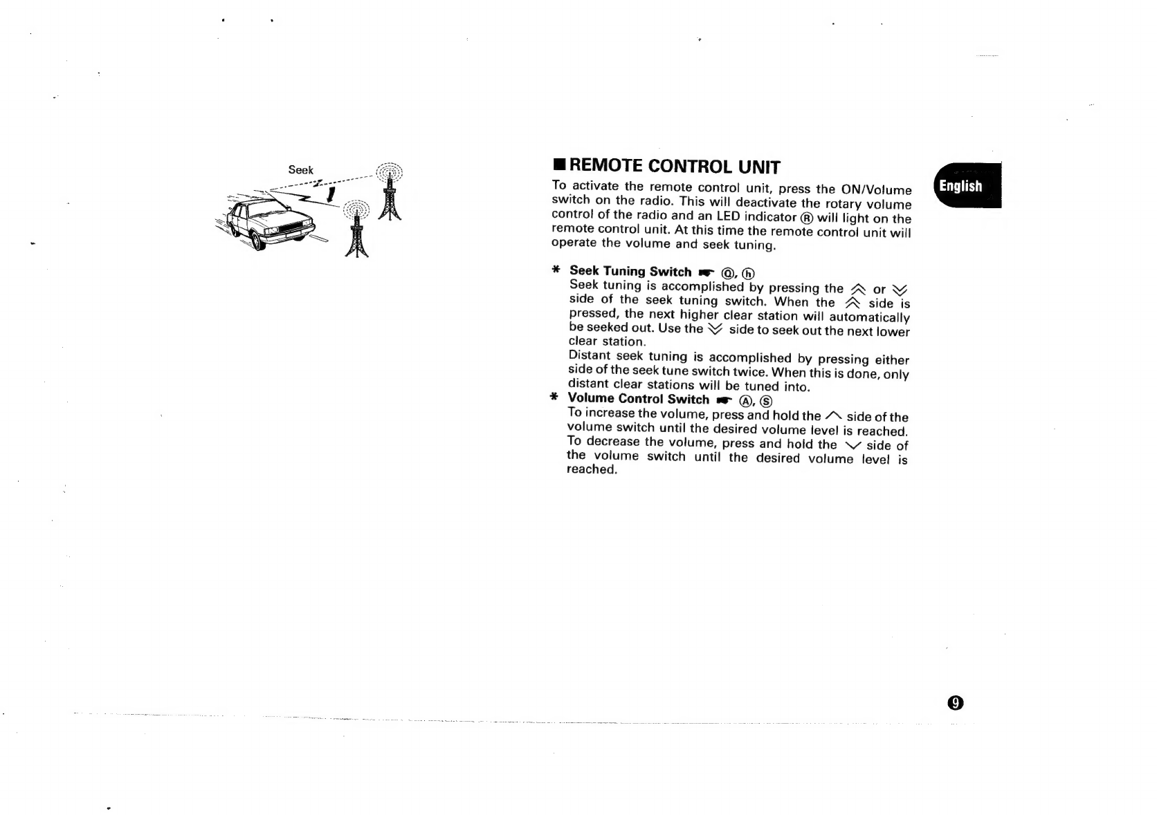
OPERATION
...............0000..
PU-9203A
Owner’s
guide
Manuel
de
lutilisateur
Bedienungsanleitung
FM-MPX/MW/LW
RADIO
CASSETTE
COMBINATION
WITH
REMOTE
CONTROL
UNIT
2aF
COMBINAISON
RADIO-CASSETTE
FM-MPX/PO/
GO
AVEC
UNITE
DE
TELECOMMANDE
UKW-MPX/MW/LW
RADIO-CASSETTEN-
KOMBINATION
MIT
FERNBEDIENUNG
System)
............
WO
nema
nec
encetenceneasees
‘a
CATS
{Systeme
anti-vol
commandé
par
ordinateur)
...........
3
«
FONCTION
............
eee
.
CATS
(Computer-Diebstahiverhiitungssystem)
........
.«
BEDIENUNG
.............0000...
.
VORSICHTSMASSREGELN
.
ANSCHLUSSE
..................
.
CATS
(Sistema
antifurto
computerizzato)
...........
.»
FUNZIONAMENTO
............
1.
CATS
(Computergestuurd
anti-diefstal
systeem)
....
@
2.
BEDIENING
...0........0.cccccccceccseeseecenseenees
®
cmp}
VOORZORGSMAATREGELEN
...................
®
4.
KABELAANSLUITING
........0.0:.:ccccccceceees
@
1.
CATS
(Sistema
computerizado
antirrobo)
..........
®@
2.
OPERACION
.0.......ccccccccscccccccseveveceecees
®@
3.
PRECAUCIONES
.................cccccceceeeeeersenes
®
4.
CONEXIONES
.........0c:cccccccccssseseeeeeereeees
@
1.
CATS
(Computer
Anti-Theft
System)
.........
56)
2.
HANDHAVANDE
..........00..cccccceceeeeeeeeeees
@
3.
FORSIKTIGHETSATGARDER
.....................
®
4.
ANSLUTNINGAR
............0...c.ccecccceescseeeees
@
®
DIE
DEUTSCHE
BUNDESPOST
INFORMIERT
...........
@
5.
SPECIFICATIONS/SPECIFICATIONS/TECHNISCHE
DATEN
.........
@
6.
INSTALLATION/INSTALLATION/EINBAU
...............
@
2.
OPERATION
(Front
View)/FONCTION
(Vue
de
Face)/
BEDIENUNG
(Ubersicht)
....................ccccccccsecencseeeees
@
7.
FEATURES/CARACTERISTIQUES/AUSSTATTUNGSMERKMALE
.............
@.