BMW E46 User manual

Initial Print Date:10/30/00 Revision Date:12/05/00
Subject Page
E46 IHKA. . . . . . . . . . . . . . . . . . . . . . . . . . . . . . . . . . . . . . . . . . . . . . . . 4
Control Panel. . . . . . . . . . . . . . . . . . . . . . . . . . . . . . . . . . . . . . . . . . . 4
Fresh Air Micro Filter. . . . . . . . . . . . . . . . . . . . . . . . . . . . . . . . . . . . . . 5
Te perature Regulation - Heating. . . . . . . . . . . . . . . . . . . . . . . . . . . . 6
Te perature Regulation - Cooling. . . . . . . . . . . . . . . . . . . . . . . . . . . . 7
Co pressor Control. . . . . . . . . . . . . . . . . . . . . . . . . . . . . . . . . . . . . . 8
Stepper Motor M-Bus Control. . . . . . . . . . . . . . . . . . . . . . . . . . . . . . .9
Convertible Rear Window Defroster. . . . . . . . . . . . . . . . . . . . . . . . . . 10
IHKA Personalization. . . . . . . . . . . . . . . . . . . . . . . . . . . . . . . . . . . . .12
Syste Operation. . . . . . . . . . . . . . . . . . . . . . . . . . . . . . . . . . . . . . .13
Diagnosis and Troubleshooting. . . . . . . . . . . . . . . . . . . . . . . . . . . . . 13
E46 IHKA I.P.O. . . . . . . . . . . . . . . . . . . . . . . . . . . . . . . . . . . . . . . . . 14
Solar Sensor. . . . . . . . . . . . . . . . . . . . . . . . . . . . . . . . . . . . . . . . . . . . 15
Purpose of the Syste .. . . . . . . . . . . . . . . . . . . . . . . . . . . . . . . . . . .16
Solar Radiation. . . . . . . . . . . . . . . . . . . . . . . . . . . . . . . . . . . . . . 17
Solar Sensor. . . . . . . . . . . . . . . . . . . . . . . . . . . . . . . . . . . . . . . . 17
Co ponents. . . . . . . . . . . . . . . . . . . . . . . . . . . . . . . . . . . . . . . . . . 18
Syste Operation. . . . . . . . . . . . . . . . . . . . . . . . . . . . . . . . . . . . . . .20
Table of Contents
E46 CLIMATE CONTROL

Subject Page
Control Curves
Blower Intervention. . . . . . . . . . . . . . . . . . . . . . . . . . . . . . . . . . . 21
Te perature Intervention. . . . . . . . . . . . . . . . . . . . . . . . . . . . . . . 22
Ventilation Intervention. . . . . . . . . . . . . . . . . . . . . . . . . . . . . . . . . 23
Diagnosis. . . . . . . . . . . . . . . . . . . . . . . . . . . . . . . . . . . . . . . . . . . . . 24
Workshop Hints. . . . . . . . . . . . . . . . . . . . . . . . . . . . . . . . . . . . . . . . 25
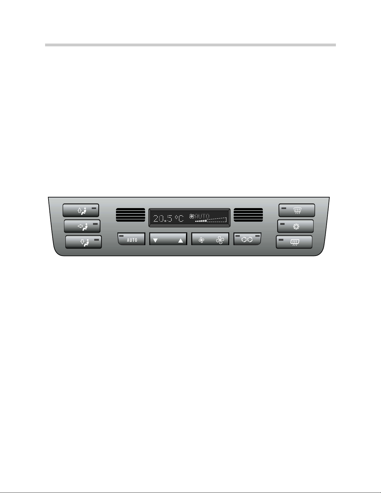
E46 IHKR. . . . . . . . . . . . . . . . . . . . . . . . . . . . . . . . . . . . . . . . . . . . . . . 26
Purpose of the Syste . . . . . . . . . . . . . . . . . . . . . . . . . . . . . . . . . . . 27
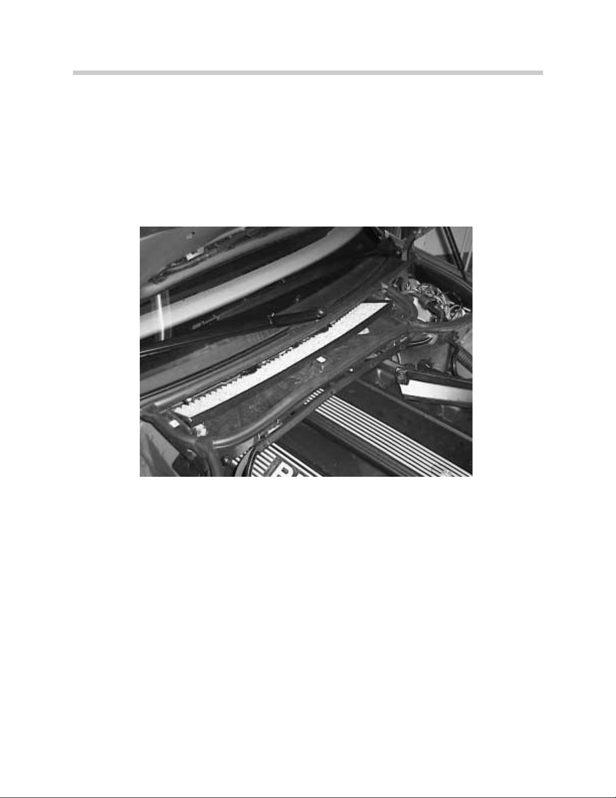
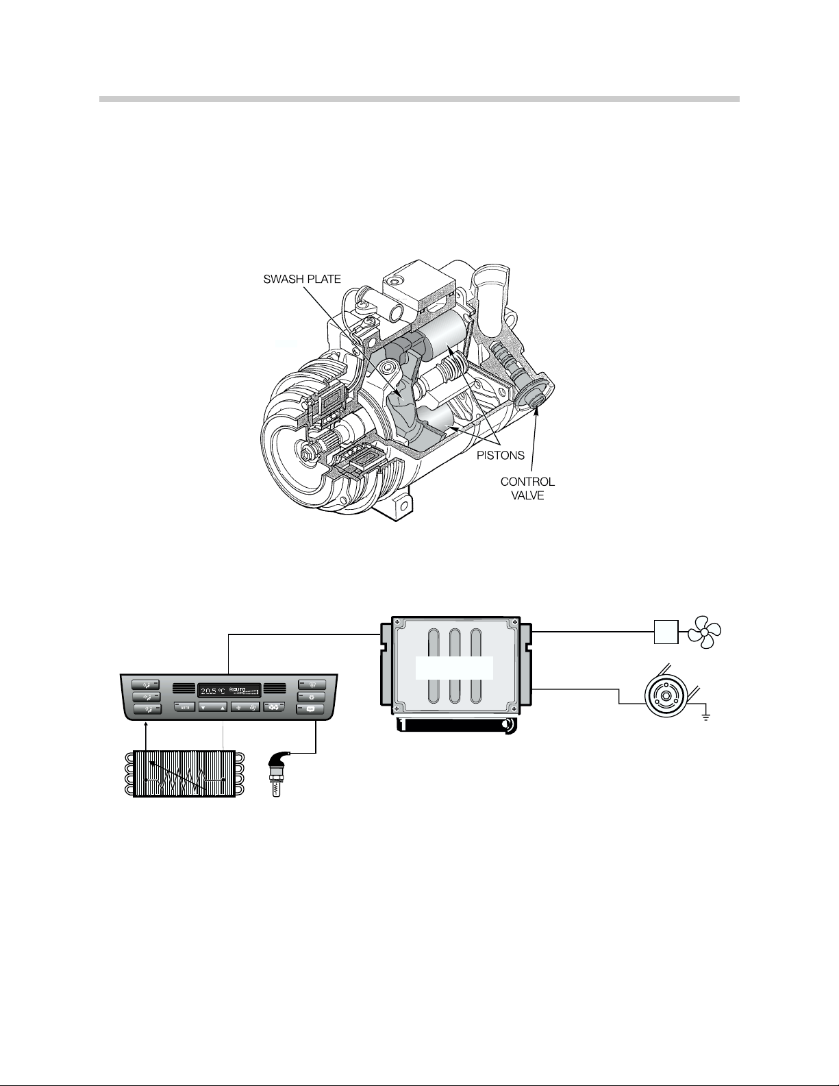
Syste Co ponents. . . . . . . . . . . . . . . . . . . . . . . . . . . . . . . . . . . . .28
IHKR I.P.O. . . . . . . . . . . . . . . . . . . . . . . . . . . . . . . . . . . . . . . . . . 29
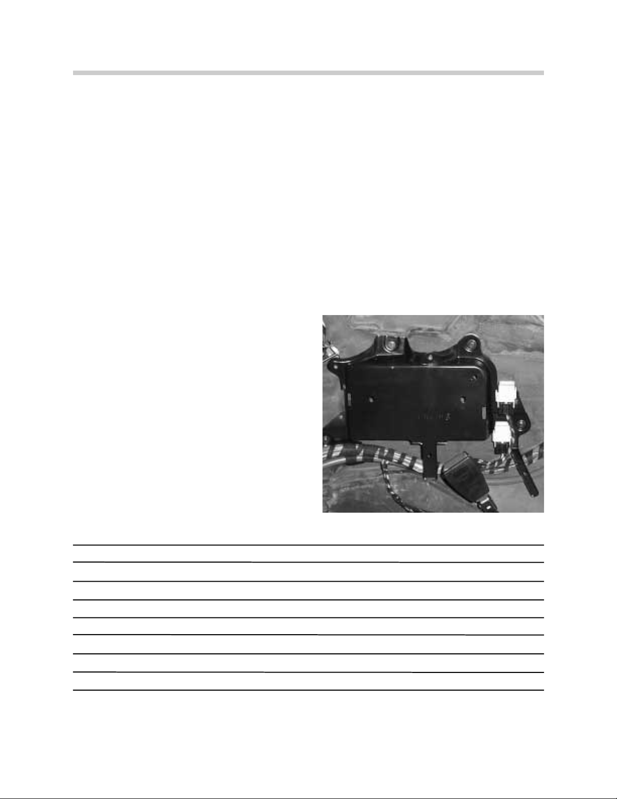
IHKR Control Unit. . . . . . . . . . . . . . . . . . . . . . . . . . . . . . . . . . . . 30
IHKR Housing. . . . . . . . . . . . . . . . . . . . . . . . . . . . . . . . . . . . . . . 30
Principle of operation. . . . . . . . . . . . . . . . . . . . . . . . . . . . . . . . . . . . .31
Blower adjust ent. . . . . . . . . . . . . . . . . . . . . . . . . . . . . . . . . . . .31
Air Distribution. . . . . . . . . . . . . . . . . . . . . . . . . . . . . . . . . . . . . . .31
Te perature Control. . . . . . . . . . . . . . . . . . . . . . . . . . . . . . . . . . 32
Engine Map Cooling. . . . . . . . . . . . . . . . . . . . . . . . . . . . . . . . . . .33
Service Station Feature. . . . . . . . . . . . . . . . . . . . . . . . . . . . . . . . 33
Air Conditioning Control. . . . . . . . . . . . . . . . . . . . . . . . . . . . . . . . 34
Air Intake. . . . . . . . . . . . . . . . . . . . . . . . . . . . . . . . . . . . . . . . . . .35
Ra Effect Air Co pensation. . . . . . . . . . . . . . . . . . . . . . . . . . . .35
Rear Window Defroster. . . . . . . . . . . . . . . . . . . . . . . . . . . . . . . . 36
Workshop Hints. . . . . . . . . . . . . . . . . . . . . . . . . . . . . . . . . . . . . . . . 37
Re iew Questions. . . . . . . . . . . . . . . . . . . . . . . . . . . . . . . . . . . . . . . . 39

3
E46 Cli ate Control
E46 IHKA
Model: E46
Production Date: From 6/98
Objecti es
After co pleting this odule you should be able to:
• Know how to replace the Fresh Air Micro Filter.
• Describe the cli ate control functions perfor ed by the IHKA control unit.
• Explain the co pressor activation circuit.
• Recognize Car and Key Me ory progra ing possibilities.

E46 IHKA Climate Control
The IHKA heater/air conditioner in the E46 is si ilar to the syste previously installed in the
E36. Design and co ponent changes were ade to i prove the overall perfor ance and
operation of the syste . This odule will deal with the changes and highlights of the E46
IHKA syste . Features of the IHKA syste include:
• Control Panel/Module
• Single heater core for te perature regulation
• M-Bus Control of all stepper otors
• Fresh air icro filter
• Regulated A/C co pressor
• Regulated auxiliary fan operation
• Heater Control Personalization
CONTROL PANEL
All heating and air conditioning functions are carried out at the control panel. The panel is
constructed as follows:
• The three anual air distribution buttons are located on the left side of the panel for
upface vent and footwell distribution.
• The auto atic air distribution button is located on the botto of the panel along with
the te perature control - blower speed control and recirculation control buttons.
• The defrost, air conditions request and rear window defogger buttons are located on
the right side of the panel.
• The LCD atrix displays the requested te perature setting and blower speeds as on
the previous syste . There is now only one setting for te perature control.
• The interior te perature sensor and blower fan are located on the left side of the LCD
atrix.
4
E46 Cli ate Control
A

FRESH AIR MICRO FILTER
The fresh air icro filter is installed in the fresh air inlet of the engine co part ent. The fil-
ter can be serviced quickly by re oving the plastic cover and re oving the filter.
5
E46 Cli ate Control

TEMPERATURE REGULATION-HEATING
The E46 uses one water valve/heater core as part of interior te perature regulation. The
water valve is pulsed to control the flow of coolant through the heater core as on other sys-
te s.
Te perature regulation is based on the inputs fro :
• Te perature control switch
• Interior te perature sensor
• A bient te perature signal
• Heater core sensor
• Evaporator te perature signal
• "Y" factor
The rocker switch is used to select the desired cabin te perature which is displayed in the
atrix of the control panel. The range for te perature display is fro 60 to 90 ° F.
SERVICE STATION FEATURE - The "Service Station" feature introduced with the E38 IHKA
is integrated into the E46 IHKA. This prevents the heater core fro being flooded with hot
coolant when refueling the vehicle.
6
E46 Cli ate Control

TEMPERATURE REGULATION - COOLING
Air conditioning control on the E46 is si ilar to the E39 IHKA syste . The syste uses the
variable displace ent co pressor. The swash plate of the co pressor is hinged so that is
can vary the piston travel based on the output require ents of the syste .
A
MS42.0
MS42.0
AUX. FANAUX. FAN
COMPRESSOR
PRESSURE
SENSOR
EVAPORATOR
7
E46 Cli ate Control

COMPRESSOR CONTROL
Control of the A/C co pressor is a function of the Engine Control Module as in the E36.
However, the control has changed to include the regulated auxiliary fan operation.
Pressing the snowflake button is a request for A/C activation. As long as the evaporator
te perature is Above 36° F, the IHKA will signal the DME control odule to activate the
co pressor.
The IHKA control odule sends the following signals to the DME over the K-Bus and CAN
Bus via the instru ent cluster:
• Request for A/C activation (signal KO)
• Load torque for switching the co pressor on
• Requested auxiliary fan speed
The IHKA deter ines the load torque for co pressor activation and required auxiliary fan
speed fro the pressure sensor ounted on the receiver/dryer.
The pressure sensor provides a linear voltage input signal (0 - 5 volts) to the IHKA control
odule. The IHKA processes this signal and deter ines the load torque of the syste (0
to 30 N with a variable displace ent co pressor). The higher the pressure in the syste ,
the higher the voltage input signal to the IHKA.
The output signal to the DME will enable the engine control odule to odify the idle
speed, ti ing and fuel injection a ount based on the load that will be i posed when the
co pressor is activated.
The auxiliary fan is now a variable speed fan (15 stages) based on the syste load. The
DME will activate the fan through a pulse odulated final stage control.
8
E46 Cli ate Control

STEPPER MOTOR M-BUS CONTROL
The E46 uses the M-Bus for stepper otor control. All five stepper otors of the IHKA
are bus controlled including:
• Two fresh air/recirc-air flap otors
• Face vent flap otor
• Footwell flap otor
• Defrost flap otor
Due to the require ent for a fast acting otor for the fresh/recirc flaps, two different step-
per otors (slow/fast) are used in the syste .
9
E46 Cli ate Control

10
E46 Cli ate Control
CONVERTIBLE REAR WINDOW DEFROSTER
Purpose of the System:
A two relay syste was designed for the E46iC that supplies power to either rear window
defogger grid. The two relay syste will also co unicates with the audio syste a plifi-
er to change the dyna ics of the sound for either top up/hard top installed or top down
driving
Components of the System:
Two relays, located on the right side rear quarter panel behind the interior tri cover, are
used for rear defroster operation.
• Relay K-13 receives KL 30 and the activa
tion signal fro the IHKA control odule.
The output fro the relay will switch the
rear defroster ON if the hard top is installed.
• Relay K-99 receives KL 30 fro relay K-13
and it supplies the rear defogger grid in the
soft top glass window when the top is
raised.

11
E46 Cli ate Control
System Operation
The rear defroster operation is a function of the IHKA syste , with the control odule
responsible for switching the syste ON/OFF. Two rear defrosted grids are used, one
installed in the soft top rear glass and the other in the optional hard top rear glass.
When the button is pressed on the IHKA control panel, Relay K-13 is energized. If the hard
top is installed, power is supplied to the grid through the connector strip on the hard top
lock.
Relay K-13 also supplies KL 30 to relay K-99 when the button is pressed on the IHKA con-
trol panel. Relay K-99 is energized when KL R is switched ON and the soft top is closed
and locked to the windshield fra e. This allows the grid in the soft top window to be heat-
ed. When the soft top is lowered, KL R to relay K-99 is interrupted by the CVM to prevent
the grid fro heating when the top is lowered into the storage co part ent.
30
30 15
31
61E46DEFROSTER0200
KL 31
CVM
Top Closed and
locked to fra e.
12V
Open and
unlocked.
0V K-13
Rear window
defogger relay
(for hard top).
Audio
Amp.
IHKA
Control Unit
Rear window
defroster grid
To hard top rear
window contact.
K-99
Rear window
defogger relay.

IHKA PERSONALIZATION
The features of Car/Key Me ory allow various functions/features of the IHKA control to be
tailored to the individual owner's/driver's wishes.
The functions of the IHKA that can be progra ed to the owner's/driver's wishes include:
• Auto atic activation of recirc when the vehicle is started
• Adjust ent (raising/lowering) of the blower speed
• Auto atic opening of the ventilation flaps with war coolant
• Auto atic closing of the footwell flap with A/C activation
• Auto atic closing of the defroster flaps with A/C activation
• Correction of the set te perature (raise/lower)
• Auto atic activation of the co pressor control when the ignition is switched on
• Auto progra for the blower control when the ignition is switched on
These features are progra ed using the coding/progra ing function of the DIS/MoDiC.
• Recirc
Air Memory
UNLEADED GASOLINE ONLY
0
12
20
km/h
MPH
1/min
x1000
40
6080 100 120 140 160
180
200
220
240
1
0
2345
6
7
50 30 20 15 12
20
40
60 80 100
120
140
11
MoDiC
20 PIN
DIAGNOSTIC
CONNECTION
MoDiC
D-BUS
DIS
A
IHKA
Units Display Change
12
E46 Cli ate Control

SYSTEM OPERATION
The balance of the E46 IHKA syste 's features and operation carry over fro the E36
including:
• Maxi u defrost operation
• Rear window defogger operation
• Final stage blower control
• Road speed dependent fresh air flap operation
• Air distribution control
• Stepper otor calibration run
• Cold start interlock
DIAGNOSIS AND TROUBLESHOOTING
The "self diagnostics" of the IHKA control odule onitors the status of inputs and outputs
of the syste . If a fault is detected, it is initially entered in RAM and than in the EEPROM
when the ignition is switched off. If available, a replace ent value will be activated when
various sensor faults are detected as with previous syste s. A axi u of six faults can
be stored in the EEPROM when the ignition is switched off.
The E46 IHKA is connected to the diagnostic link via the K -Bus/instru ent cluster. The
syste uses the E46 "Fault Sy pto Troubleshooting " procedures for troubleshooting
proble s and faults with the syste .
When troubleshooting proble s with the E46 IHKA, it is i portant to note that because the
Car/Key Me ory feature can change the functionality of the syste , a review of the set-
ting should be perfor ed prior to conde ning a co ponent as faulty.
13
E46 Cli ate Control

14
E46 Cli ate Control
E46 IHKA I.P.O
As introduced.

15
E46 Cli ate Control
SOLAR SENSOR
Model: E38, E39, E46
Production Date: E38 3/99, E46 9/99, E39 9/00
Objecti es
After co pleting this odule you should be able to:
• Describe the operation of the solar sensor as it applies to the IHKA syste s.
• List the output functions effected by the solar sensor input.
• Describe how the solar sensor affects the various output functions.

16
E46 Cli ate Control
Purpose of the System:
The purpose of the solar sensor is to co pensate the cli ate control syste ’s output for
the radiant heating effect of the sun. This will aid the IHKA in aintaining a constant co -
fort level, in the vehicle’s interior, during all driving conditions.
The function of heating and air conditioning syste s in BMW vehicles is to provide the dri-
ver and passengers a co fortable at osphere regardless of conditions outside of the vehi-
cle. Based on the te perature signal inputs, blower setting, flaps portioning, progra set-
tings in the control odule and influencing variables, the IHKA control odule is able to
process these inputs to achieve the desired co fort level.
The following input variables are
processed by the IHKA odule:
• Interior te perature
• Heat exchanger te perature
• Ventilation te perature (E38)
• Evaporator te perature
• Air volu e setting
• Engine te perature and RPM
• Exterior te perature
The processed variable “Y-factor” is deter ined by using the above inputs. The Y-factor
then represents how uch adjust ent is necessary by the IHKA odule to achieve the set
te perature.

17
E46 Cli ate Control
Solar Radiation
Solar radiation, fro the sun, passes through the earths at osphere in the for of light
(both visible and non-visible) and heat (sunshine). To date, the influence of solar radiation
on the cli ate control syste in the vehicle has only been co pensated for by an average
value stored in the control odule and based on control settings and outside te perature
values.
Solar Sensor
The solar sensor can detect the a ount of solar radiation that is influencing the te pera-
ture and cli ate in the vehicles interior. The IHKA control odule onitors the input fro
the solar sensor and adds the value to its processing factors. The settings of the cli ate
control syste are changed to co pensate for this additional influence.
The settings of the following IHKA co ponents are adjusted to co pensate for changes
in solar radiation:
• Blower - The blower curve is changed
• Stratification ( ixing flaps) - The stratification outlet air te perature is changed (not E46)
• Ventilation - The opening angles of the ventilation flaps are changed.

18
E46 Cli ate Control
Components:
In the E38, The solar sensor is integrated in the housing of the anti-theft warning syste
LED. The warning indicator LED is installed on the outlet grille in the top center of the
instru ent panel where solar radiation can directly reach the solar sensor.
The DWA LED with solar sensor is an additional wiring harness with a 4-pin plug connec-
tor.
DWA LED with integrated solar sensor
_____________________________________________________________________________
_____________________________________________________________________________
_____________________________________________________________________________
_____________________________________________________________________________
_____________________________________________________________________________
_____________________________________________________________________________
_____________________________________________________________________________
_____________________________________________________________________________
_____________________________________________________________________________
_____________________________________________________________________________
_____________________________________________________________________________
_____________________________________________________________________________
_____________________________________________________________________________
_____________________________________________________________________________
_____________________________________________________________________________
_____________________________________________________________________________
_____________________________________________________________________________
1
23
DWA LED plug connector
4-pin solar sensor plug connector
DWA LED/SOLAR SENSOR MODULE

19
E46 Cli ate Control
The solar sensor consists of two photoresistors, which are integrated on the left and right
sides of the DWA housing next to the DWA LED. The photoresistors sense the different
intensity levels of the solar radiation.
DWA LED dismantled; housing and pc-board with LED and solar sensor housing
1The photoresistor on the right is fitted under
the plastic cover
2The photoresistor on the left is fitted under the
plastic cover
3PC-board, DWA LED and solar sensor
4DWA LED housing
The E46 solar sensor is located in the right
defroster outlet at the base of the windshield.
The E46 sensor contains one photoresistor for
sensing solar radiation.
1
2
3
4
SOLAR SENSOR

System Operation
The solar sensor receives power (5 volts) and ground fro the IHKA control odule. The
odule then reads the voltage drop across the photoresistor and deter ines the degree of
solar heating based on the change in voltage. The voltage drop across the photoresistor
increases as solar radiation increases. The IHKA control odule onitoring voltage will
decrease indicating an increase in solar heating. The odule processes the input every 10
seconds and checks it for plausibility based on a li it value onitoring function.
Values outside the li it indicate a alfunction and the signal fro the sensor is ignored by
the odule.
As solar radiation levels increase, the control curves, stored in the IHKA odule, for the
blower fan, ixing flaps and ventilation (face vent) flaps are shifted to co pensate for the
additional heat.
The solar sensor inputs to the IHKA control odule can influence the settings on the rele-
vant side (driver/front passenger) on the E38 and E39. No separate regulation is possible
on the E46.
When driving at night, during cloudy periods or through tunnels, the control aps are shift-
ed back to their base settings.
20
E46 Cli ate Control
Other manuals for E46
2
Table of contents