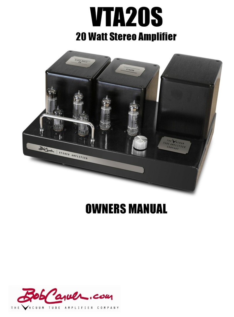
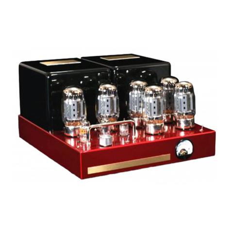
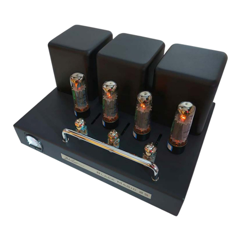
Bob Carver 350 Watt Vacuum Tube Amplifier User manual

350 Watt Vacuum Tube
Amplifier
Owner’s Manual

1
CIRCUIT DESCRIPTION
The$input$stage$consists$of$a$12AX7$current$sourced$long-tailed$balanced$pair,$which$is$direct$
coupled$to$a$second$long-tailed$balanced$pair$comprised$of$a$12AT7.$$The$12AT7$drives$the$grids$of$
the$KT150/KT120$output$tubes$through$a$pair$of$coupling$capacitors$that$provide$low$frequency$
loop-gain$stability.$A$6AL5$DC$restorer$ensures$that$the$bias$voltage$remains$correct$over$the$
entire$audio$signal$cycle.$
The$output$tubes$are$arranged$in$push-pull$parallel,$three$up,$three$down$for$a$total$of$six$in$all.$$
The$screen$grids$are$operated$at$approximately$360$volts$provided$by$a$separate$power$supply$
formed$by$one-half$of$a$voltage$doubler$supplying$the$plates$with$720$volts.$
The$power$supply$consists$of$a$large$power$transformer,$with$energy$storage$that$is$far$greater$
than$necessary.$AC$filament$voltage$is$biased$to$approximately$60$volts.$Multiple$decoupling$filter$
sections$are$used$with$load$regulation$obtained$through$constant$current$loading.$
Turn-on$in-rush$current$limiting$is$provided$by$a$thermistor,$bias$voltage$adjustment$by$a$bias$
control,$feedback$gain$by$a$top-mounted$front$panel$switch,$volume$by$a$volume$control,$and$bias$
voltage$is$measured$across$a$one$ohm$sense$resistor$that$senses$current$for$all$six$output$tubes$
simultaneously.$$A$tube$fuse$is$mounted$on$the$rear$apron$and$provides$protection$for$the$output$
section$in$the$event$of$a$catastrophic$vacuum$tube$failure.$$Additionally,$a$rear$mounted$power$
line$fuse$provides$overall$protection$for$the$amplifier.$
VACUUM TUBES
The$output$tubes$do$not$need$to$be$matched,$as$the$sound$of$the$amp$does$not$at$all$depend$on$
matched$output$tubes.$That's$because$the$DC$restorer$circuit$eliminates$the$need$to$match$tubes.$
The$only$caveat$here$is$that$the$output$tubes$should$all$be$the$same$type$and$vintage.$
Looking$at$the$amplifier$from$the$front,$from$left$to$right:$the$first$tube$is$a$12AX7,$then$a$12AT7,$
and$finally$the$6AL5.$The$output$tubes$are$KT120's.$$Any$of$the$popular$derivatives$such$as$'88,$'90,$
or$'100$may$also$be$installed.$The$mighty$6550$may$be$used$as$well,$even$the$ubiquitous$EL34.$
However,$performance$will$suffer$a$bit$with$the$EL34$because$the$design$has$been$optimized$for$
the$KT88$/$KT120$/$6550.$
FEEDBACK SWITCH
The$small$switch$mounted$on$the$top$front$of$the$chassis$controls$the$amount$of$negative$
feedback$used.$$When$the$toggle$handle$is$pushed$LEFT$(classic),$the$feedback$is$approximately$20$
dB,$a$value$used$by$almost$all$vintage$amplifier$designers$and$is$my$personal$preference.$When$
toggled$RIGHT$(contemporary),$feedback$is$limited$to$about$11$dB.$$This$represents$the$practice$of$
many$modern$day$designers.$$Please$try$it$both$ways$and$make$your$own$determination$based$on$
your$listening$experience$and$your$speakers.$
VOLUME CONTROL
Under$normal$circumstances,$this$control$should$remain$in$the$maximum$(fully$clockwise)$
position.$If$you$have$a$noisy$preamp,$turning$it$halfway$down$and$centering$it$at$the$12:00$o'clock$
position$will$reduce$the$preamp$noise$by$half,$or$6$dB.$It$should$always$be$turned$all$the$way$down$
(fully$counterclockwise)$when$connecting$or$disconnecting$any$input$or$output$in$your$system.$

2
Either$the$XLR$(balanced)$or$RCA$(single-ended)$audio$input$jacks$are$used$to$feed$the$signal$into$
the$amplifier$from$your$signal$source.$
FUSES
The$rear$panel$line$fuse$is$a$6$ampere$(3$ampere$for$240$volt$operation),$fast$blow$type,$and$
should$be$replaced$with$the$same$type$and$rating$if$it$ever$needs$replacing.$Do$not,$under&any&
circumstances,$use$a$"slow-blow"$fuse$here.$The$(rear$panel)$vacuum$tube$cathode$fuse$is$a$1.0$
ampere$and$should$be$replaced$with$the$same$type$and$rating.$$If$the$fuse$blows$during$bench$
testing,$it$may$be$temporarily$replaced$with$a$1.25$or$1.5$ampere$fuse.$Normally,$a$1.0$ampere$
fuse$will$be$perfect$for$music$because$the$peak-to-average$power$ratio$of$speech$and$music$is$
about$10:1.$If$you$find$that$the$1.0$amp$fuse$blows$with$music,$you$may$replace$it$with$a$1.25$
ampere$fuse,$or$even$a$1.5$ampere$unit.$$
ADJUSTING THE OUTPUT TUBE BIAS
The$front$panel$incorporates$a$bias$meter.$Turn$the$volume$control$all$the$way$down$while$
performing$bias$adjustments.$Use$a$small$screwdriver$and$adjust$the$bias$control$(located$on$the$
rear$of$the$amplifier)$for$80$mA$after$the$unit$has$warmed$up$for$about$20$minutes.$The$normal$
range$to$use$is$from$60$mA$to$150$mA,$and$changes$here$will$vary$the$damping$factor$of$the$
amplifier$slightly.$More$current$increases$the$damping$factor,$whereas$less$current$provides$a$
softer$more$tube-like$sound.$The$design$center$is$80$mA,$and$that$should$be$your$starting$point$if$
you$want$to$experiment.$Personally,$I$found$that$I$loved$the$sound$best$on$my$speakers$when$I$
had$it$set$for$their$design$center$of$80$mA.$It$will$vary$from$speaker$to$speaker,$and$most$
importantly$with$your$taste.$
The$meter$reads$the$combined$current$for$all$six$output$tubes,$and$it$is$normal$for$this$current$to$
vary$slightly$with$changes$in$power$line$voltage.$
SPEAKER CONNECTIONS
From$the$rear$view:$the$black$binding$post$is$common,$and$(moving$to$the$right)$the$next$red$post$
is$two$ohms,$then$four$ohms,$and$the$far$right$post$is$for$eight$ohms.$The$power$curve$is$quite$flat,$
hence$the$two$ohm$tap$may$be$used$for$one$ohm$speakers,$and$the$eight$ohm$tap$may$be$used$
for$sixteen$ohm$speakers.$
POWER SWITCH
Up$is$on,$down$is$off.$$There$is$no$power-on$indicator$except$for$the$glow$of$the$tubes,$so$you$will$
have$to$remember$whether$you$turned$it$on$for$about$10$seconds$until$you$can$see$the$tubes$
glow.$$It$is$safe$to$switch$the$amplifier$on$and$off$at$will.$
LINE VOLTAGE
This$amplifier$may$be$configured$for$operation$with$120$volts$or$240$volts,$50$/$60$Hz.$The$
changeover$must$be$performed$by$qualified$personnel.$It$is$a$standard$under$the$chassis$wiring$
configuration.$See$the$circuit$diagram$for$details.$$$$When$used$with$240$volts,$the$AC$line$fuse$
must$be$replaced$with$a$3$ampere$unit.$

3
COOLING
Convection$cooling.$Cool$air$is$drawn$from$under$the$chassis$by$the$heat$from$the$tubes$acting$as$
an$air$pump,$and$exhausting$the$warm$air$out$the$chassis$through$the$top$vents.$Do$not$place$the$
amplifier$on$a$carpet$without$something$hard$to$sit$on$like$a$piece$of$nice$glass$cut$to$the$same$
size$as$the$unit.$This$will$allow$the$feet$to$do$their$job$by$keeping$the$bottom$raised,$allowing$
unimpeded$airflow.$$A$glass$shop$can$make$such$a$base$plate$and$in$colors$if$you$wish.$A$nice$
translucent$brown,$burgundy$or$smoke$looks$beautiful.$It$should$be$at$least$a$quarter$of$an$inch$
thick.$12$1/4”$X$14$1/2”.$
MONITORING
Once$the$idling$current$has$been$set,$it$will$normally$not$need$to$be$adjusted$for$several$years$
unless$you$want$to$experiment$for$different$sound.$$Or$if$you$install$different$output$tubes,$or$the$
amplifier$suddenly$starts$to$sound$funny.$If$you$hear$a$POP$and$see$a$flash,$yet$the$amp$continues$
to$play,$you$should$first$check$the$current$and$then$the$output$tube$fuse.$$If$the$fuses$blow,$the$
output$current$will$drop$to$zero.$If$the$tube$fuse$blows,$replace$it$WITHOUT$replacing$any$tubes.$
Turn$the$amp$on$and$monitor$the$current.$If$it$climbs$to$within$the$range$you$had$set,$and$if$the$
amp$sounds$good,$all$is$well.$
Often,$an$output$tube$has$a$speck$of$dust-like$impurity,$which$comes$into$contact$with$an$internal$
element,$shorting$the$element,$and$is$vaporized$into$gaseous$oblivion.$The$getter,$the$mirror-like$
shiny$plating$on$the$inside$of$the$tube$does$its$job,$absorbs$the$vaporized$material$and$the$tube$is$
like$new$again.$All$it$takes$is$a$new$fuse.$
If$you$install$a$new$fuse$and$it$blows$again,$you$will$need$to$determine$which$tube$is$the$culprit.$
Proceed$as$follows:$remove$all$output$tubes$and$turn$the$volume$control$all$the$way$down.$Turn$
the$amp$on$and$leave$it$on.$While$monitoring$the$current,$put$a$pair$of$tubes$into$sockets$number$
five$and$number$six.$Allow$one$minute$on$the$clock$for$the$two$tubes$to$warm$up.$If$the$current$
comes$up$to$about$one$third$the$normal$amount,$both$those$tubes$are$good.$Remove$those$tubes$
and$install$another$pair,$also$in$sockets$five$and$six.$Continue$on$until$a$fuse$blows,$or$the$tubes$
won't$bias$up.$
Then$borrow$a$known$good$tube$from$the$other$amplifier,$and$using$it$as$a$mate,$place$it$
temporarily$in$socket$number$five,$use$the$process$of$elimination$to$figure$out$which$of$the$last$
two$tubes$is$bad.$At$this$point,$if$you$get$lucky,$only$one$trial$will$be$needed.$If$you$are$not$lucky,$
then$it$will$take$two$trials.$Now$you$can$turn$the$amp$off.$$
You$will$be$able$to$install$and$remove$the$tubes$with$your$bare$fingers$if$you$do$it$within$about$a$
minute$or$so$of$installing$each$fresh$set.$That's$because$it$takes$substantially$longer$than$a$minute$
for$the$tubes$to$get$too$hot$to$hold.$

4
TUBE TESTER
The$front$panel$meter$may$be$used$to$test$the$tubes.$Remove$all$the$power$output$tubes;$plug$the$
amp$into$the$AC$wall$socket$with$the$main$rear$panel$power$switch$OFF.$
Insert$the$tube$you$wish$to$test$into$socket$#6$(the$far$right$front$socket).$Turn$the$bias$control$
such$that$the$slot$is$at$12:00$o’clock$(straight$up$and$down)$and$turn$the$main$power$switch$ON.$
With$a$watch,$time$the$warm-up$period$for$exactly$one$and$a$half$minutes$and$note$the$current$
reading.$Turn$the$amplifier$OFF,$$
Remove$the$tube$and$insert$the$next$one.$You$can$hold$the$tube$with$your$bare$fingers$-$it$will$not$
be$too$hot$after$only$a$minute$and$a$half,$provided$it$was$cool$to$start$with.$Keep$track$of$each$
reading,$and$repeat$until$all$tubes$have$been$checked.$If$any$single$tube$does$not$bias$up$or$“runs$
away”$with$its$current$climbing$substantially$higher,$≈200%$than$the$others,$then$it$must$be$
replaced.$$It$is$okay$to$turn$the$amp$on$and$off$at$will.$$Return$the$bias$control$to$its$original$
position$and$put$all$the$tubes$back$into$their$sockets.$This$completes$the$tube$testing$operation.$
MATCHING OUTPUT TUBES
Matching$output$tubes$is$not$necessary,$thanks$to$the$DC$restorer.$But$it’s$fun$to$do$anyway.$As$
noted$above,$as$you$wrote$down$each$bias$current,$you$will$end$up$with$six$numbers.$The$goal$is$
to$select$two$groups$of$three$whose$sum$(from$any$three$tubes)$is$as$close$as$you$can$get$to$the$
other$group$of$three$tubes.$Install$the$first$group$in$sockets$#1,$#3,$and$#5,$the$odd$sockets.$$Then$
install$the$other$group$into$sockets$#2,$#4,$and$#6,$the$even$sockets.$The$socket$positions$on$the$
amp,$from$left$to$right,$looking$from$the$front$are:$#1,$#2,$#3,$and$#4.$$The$last$two$positions,$#5$
and$#6,$are$the$front$tubes$on$the$right.$
The$new$KT120’s$are$quite$variable,$and$I$recommend$that$when$using$the$KT120$tube,$one$should$
go$through$the$exercise$of$matching$them$as$outlined$above.$
SMALL TOGGLE SWITCH
There$is$a$small$toggle$switch$on$the$top$front,$and$it$controls$the$feedback$as$mentioned$earlier.$
Thrown$left$=$classical,$right$=$contemporary.$$$
NEW AMPLIFIER SMELL
Like$a$brand$new$car,$this$amplifier$possesses$a$"new$amplifier$smell,"$even$though$it$has$been$
built$from$both$new$and$vintage$parts.$When$powered$up$for$the$first$time,$the$fresh$paint$and$
recent$skin$oils$on$the$tubes$will$create$a$new,$hot$amp$smell.$I$find$it$sort$of$pleasant,$but$you$
may$not.$It$will$dissipate$with$use,$usually$requiring$about$four$weeks$of$normal$operation.$

5
SPECIFICATIONS
Gain$$$30$dB$
Power$$$More$than$350$Watts$
Noise$$$Better$than$100$dB$A-weighted,$referred$to$200$watts$
Frequency$response$2$Hz$to$85$kHz,$without$filters$
Distortion$ $ Less$than$0.5%$
Vacuum$tubes$ $ KT150$/$KT120$/$KT88$/$6550,$12AX7,$12AT7,$6AL5$
Speaker$outputs$One$ohm,$two$ohms,$four,$eight$and$sixteen$ohms$
Input$impedance$100$kohms$
Weight$$$84$pounds$for$a$stereo$pair,$42$pounds$each$$$$$
Color$Champagne$gold,$Bright$chrome,$Natural$aluminum$and$Strawberry$
metallic$Red$and$Gloss$black.$$$$$$$$$$$$$$$$$$$$$$$$$$$$$$$$$$$$$$$$$$$$$$$$$$$$$$$$$$$$$$$
Table of contents
Other Bob Carver Amplifier manuals
Popular Amplifier manuals by other brands
Genz Benz
Genz Benz GBE 750 Technical manual

Radial Engineering
Radial Engineering CHAINDRIVE 500 Series user guide

Sony
Sony TA-AV411 owner's manual

AMX
AMX DAS-TAMP4-SIG installation guide

Broadcastvision Entertainment
Broadcastvision Entertainment AudioFetch Express user manual
LY International Electronics
LY International Electronics PB9811P owner's manual

