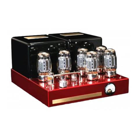
Bob Carver Crimson 275 Stereo User manual

Operating Manual
c02-15-19

The lightning ash with arrowhead, within
an equilateral triangle, is intended to alert
the user to the presence of uninsulated
“dangerous voltage” within the product’s
enclosure that may be of sucient magni-
tude to constitute a risk of electric shock
to persons.
The exclamation point within an
equilateral triangle is intended to
alert the user to the presence of
important operating and maintenance
(servicing) instructions in the literature
accompanying the appliance.
WARNING - TO REDUCE RISK
OF FIRE OR ELECTRICAL
SHOCK, DO NOT EXPOSE
THIS EQUIPMENT TO RAIN OR
MOISTURE.
NO USER-SERVICEABLE
PARTS INSIDE.
REFER SERVICING TO
QUALIFIED PERSONNEL
ONLY.
CAUTION: To reduce the risk of
electric shock, do not expose
this appliance to rain and
moisture. Do not expose this
device to dripping or splashing liquids
and no object lled with liquids, such as
vases, should be placed on the device.
IMPORTANT SAFETY INSTRUCTIONS!
PLEASE READ THEM BEFORE OPERATING
THIS EQUIPMENT.
1. Read these instructions.
2. Keep these instructions
3. Heed all warnings
4. Follow all instructions.
5. Do not use this apparatus near water.
6. Clean only with a dry cloth.
7. Install in accordance with the Bob Carver Company instructions.
8. Do not install in close proximity to heat sources such as radiators,
heat registers, stoves, replaces, or other apparatus (including
other ampliers) that produce heat.
9. Do not defeat the safety purpose of the polarized or grounding-
type plug. A polarized plug has two blades with one wider than the
other. A grounding type plug has two blades and a third grounding
prong. The wide blade or the third prong are provided for your
safety. If the provided plug does not t into your outlet, consult an
electrician for replacement of the obsolete outlet.
10. Protect the power cord from being walked on or pinched
particularly at plugs, convenience receptacles, and the point where
they exit from the power amplier.
11. Only use attachments/accessories specied by Bob Carver
Company.
12. Use only with the cart, stand, tripod, bracket, or table
recommended by Bob Carver Company. When a cart
is used, use caution when moving the cart/apparatus
combination to avoid injury from tip-over.
13. Unplug this apparatus during lightning storms or when
unused for long periods of time.
14. Refer all servicing to qualied service personnel. Servicing is
required when the apparatus has been damaged in any way, such
as power-supply cord or plug is damaged, liquid has been spilled
or objects have fallen into the apparatus, the apparatus has been
exposed to rain or moisture, does not operate normally, or has
been dropped.
15. Do not expose this equipment to dripping or splashing liquids, and
ensure that no objects lled with liquids, such as vases, are placed
on the equipment.
16. To completely disconnect this equipment from the AC mains,
disconnect the power supply cord plug from the AC receptacle.
17. The mains plug of the power supply cord shall remain readily
operable.
18. Connect mains power supply cord only to a mains socket outlet
with a protective grounding connection.
19. If possible, save the shipping carton that contained your Crimson
275, as well as the individual tube boxes.

3
Quick Start Guide
1. Locate the seven vacuum tube boxes, four large and
three small.
2. Place the Crimson 275 according to the ventilation
suggestions on page 6 of this manual.
3. Carefully insert the tubes into their sockets following
the diagram at right and the further details on page 00
of this manual.
4. Connect the outputs of your preamplier/DAC to the
RCA inputs of the Crimson 275. Make sure that the
gain/volume control on your preamplier/DAC is
turned down. See page 8 for more hook-up instruc-
tions.
5. Connect the output terminals of the Crimson 275 to
your loudspeakers. See page 8 for more details.
6. Connect the IEC power cable between the Crimson 275
power socket and the wall receptacle.
7. Power up your preamplier/DAC.
8. Flip the Crimson 275 rear panel POWER switch to
ON.
9. Wait two minutes for the tubes to warm up.
10. Activate your music source and slowly advance
the volume control on your preamplier/DAC.
11. Enjoy! If you don’t hear any sound, turn off your
preamp/DAC and Crimson 275, and re-check your
connections, or see the Troubleshooting Section
on page 00.
12AT7
KT120 KT120 KT120 KT120
12AT712AX7
L
R
R L
OUTPUT OUTPUT
R INPUT L –RIGHT + – LEFT + AC INPUT
+
–
+
–

4
“I personally wish to thank you for choosing my
Crimson 275 amplier. It has truly been a labor of
love, incorporating many of the sonic improvements
I developed for the Silver Seven 900 and Crimson/
Raven 350, as well as those from previous designs.
Along with the help of my wonderful staff, we be-
lieve that we have created both a sonic masterpiece
and an excellent value.
“It’s time to start enjoying years of musical enjoy-
ment! But rst, please take the time to read through
this brief manual to get the most from
your Crimson 275.”
Thank
you!
enlarged bitmap (JPG)
• Ample power for speaker loads from 2 ohms to
16 ohms, the musicality of premium vacuum
tubes, and the accuracy and pristine specica-
tions that come from Bob’s 50+years of design
expertise.
• Bob’s “listen to the room” innovation. Facilitated
by a special current feedback loop, it allows the
amplier to ‘hear’ the room’s reverb, along with
its unique sonic signature. Each room plays its
own tune, and this amp uses the speaker as a
microphone by using the speaker in reverse to
listen to the room,thereby allowing a portion of
the room acoustic to be expressed through the
main speakers.
The room becomes an integral part of
the music in a way no other amplier allows.
Sound is more majestic, more realistic, and the
soundstage is larger and more compelling.
This phenomenon is impossible to achieve with
normal solid-state amplier designs, whose low
source (output) impedance effectively shorts
out the speaker’s ability to accomplish this feat.
• DC Restorer circuit, an exclusive to Bob Carv-
er designs, keeps the output tubes running
cool, prolonging their life to beyond 50 years!
Other amplier tubes operate at a very high
idle power to keep distortion low, frequency
response extended, and for other technical
reasons. The downside is that tube life is dras-
tically shortened, about three to six years at
the most. Worse yet, tube performance begins
to deteriorate as soon as the amp is turned on.
In addition to extended tube life, Bob Carver
Company’s DC Restorer eliminates the need
to purchase expensive matched tubes for the
Crimson 275.
• Unique transformer design delivers enormous
power through an increased turns ratio, with
two extra interleaved windings, each bilar
wound on a core of adamantine steel with a
pure nickel center section. The secondary’s are
wound with oxygen-free copper wire and 98%
pure silver wire for the critical internal inter-
connections.
• Hand-rubbed
piano-style
nish.
Why we
are so
proud
of the
Crimson
275

5
Record This Important Information
For possible insurance claims or factory repair,
please record the serial number, purchase date
and Bob Carver Company Dealer name in the
spaces provided.
Serial Number:_________________________________
Purchase Date: _________________________________
Dealer Name: __________________________________
________________________________________________
Technical Assistance
Your Bob Carver Dealer welcomes questions
about your Crimson 275 and any other brands
that may be part of your system. If you or your
Dealer wish additional help concerning a sus-
pected problem, we’re here in rainy Snohomish,
Washington to help you.
Bob Carver Company
1429 Avenue D #396
Snohomish, WA 98290
Phone:
847.668.4519 or 360.348.5848
Email:
Frank.Malitz@BobCarverCorp.com or
Jordon.Gerber@BobCarverCorp.com
Customer Service
We are proud of the fact that we support our
ampliers far longer than any of our competitors.
Your new Crimson 275 comes with a FIVE YEAR
tube and service warranty!
If it is determined that your amp needs repair,
you should rst contact your Bob Carver Company
dealer. If you cannot located the dealer, contact
us and we will provide you with a Return Aut-
noization. For assistance, contact us at the phone
and email addresses above.
Our Limited Warranty is on page 14 of this
Manual.

6
Placement and Cooling
Cool air is drawn from under the chassis by the
heat from the tubes acting as an air pump, and
exhausting the warm air out the chassis through
the vents.
Place the amp on a hard surface. Do not place
the amplier on a carpet without something hard
for it to sit on like a piece of nice glass cut to the
same size as the unit. This will allow the feet to do
their job by keeping the bottom raised, allowing
unimpeded airow.
A glass shop can make such a base plate and
in colors if you wish. A nice translucent brown,
burgundy or smoke looks beautiful. It should be at
least a quarter of an inch thick.
We also don’t recommend placing the Crimson
275 in a tightly-enclosed cabinet without suf-
cient ventilation. Allow at least 18 inches of free
space above the amplier.
12AT7
KT120 KT120 KT120 KT120
12AT712AX7
Inserting the Vacuum Tubes.
The Crimson 275 comes with three small and
four large vacuum tubes: Two 12AT7’s, one 12AX7,
and four KT120 output tubes.
IMPORTANT: Instead of 12AT7 tubes, you
may have received tubes marked ECC81.
ECC81’s are identical to 12AT7’s.
Instead of a 12AX7, you may be received an
ECC83. ECC83 tubes are identical to 12AX7’s.
Press the tubes into the bases (sockets) gently
so that you don’t bend the pins.
The bases for all three small tubes are identi-
cal, so take care to make sure that the 12AX7 is in
the middle socket.
Tung-Sol in their innite wisdom has cong-
ured the KT120’s black, central base hole to be

7
slightly different than our conven-
tional tube bases. Look carefully so
that you line up the raised portion of
the KT120’s central base with the “key
way” on the tube base.
More About the Tubes.
The output tubes do not need to be matched,
as the sound of the amp does not at all depend on
matched output tubes. That’s because the DC re-
storer circuit eliminates the need to match tubes.
The only caveat here is that the output tubes
should all be the same type and vintage.
Looking at the amplier from the front, left
to right: the rst tube is a 12AT7, then a 12AX7,
and nally a second 12AT7. The output tubes are
KT120’s.
Any of the popular derivatives such as KT88,
KT90, or KT100 may also be installed. The mighty
6550 may be used as well — even the ubiquitous
EL34. However, performance will suffer a bit with
the EL34 because the design has been optimized
for the KT88 / KT120 / 6550. See page 10 for more
information on tube alternatives.
Why we can offer a 5-year warranty
on Crimson 275 tubes.
There is a meter on the front of the amplier
which can indicate the health of the tubes — get a
bad reading, get free tubes!
As with our more expensive ampliers, Bob
employs his unique twist on a DC restorer circuit
which has two main benets —lower distortion
without dissonant side effects and extended tube
and amplier life. Our ampliers simply do not
run hot. Like their more expensive siblings, they
are the coolest running tube type ampliers ever,
allowing you to actually touch the tops of the
mighty KT120s and never be burned! The internal
temperature of our ampliers is a bit warmer than
the inside of your mouth resulting in an indeter-
minate lifespan.
Due to the unique design, all the components
in the amplier undergo much less stress than in
conventional designs. Due to the efciency of the
concept, our transformers can be lighter and de-
spite Bob Carver specifying esoteric steel for their
cores, it helps us sell a $4000+ amplier for un-
der $3000. As with his legendary Sunre tracking
power supplies, the bottom line is that you may
expect our ampliers to outlive any other brand,
and our extended warranties underscore that fact.
We warrant the Crimson 275 for a full ve
years; that’s the amplier and the tubes! We love
the fact that our nest competitors warrant their
tubes for three months. It’s all about economics.
If your tubes tend to fail, limit the warranty. A
manufacturer has no option; they must. Since
our tubes last for years, it costs us nothing to be
heroic.
Perhaps even more importantly, not only do the
tubes no longer fail every two or three years, they
do not degrade sonically as all tubes must when
boiling away in every one of our competitors am-
pliers — a truly remarkable accomplishment and
typical for Bob Carver, Absolute Sound Magazine
Hall of Fame designer.
key way

8
General Operation.
Bob has intentionally made the Crimson 275
extremely simple to operate. Volume (gain) is
determined by your preamplier or DAC.
Tube biasing, using the rear panel control, is
optional and will be covered on page 10 of this
manual.
That’s all there is…except for connecting your
sound source, loudspeakers and line cord.
Speaker Connections.
It is very important to use speaker cables of the
correct diameter in order to reduce power loss. It
is not within the scope of this manual to discuss
various esoteric speaker cable options.
The Crimson 275 speaker terminals will accept
spade lugs, banana plugs or bare wire.
If using bare wire, remove half an inch of insu-
lation and tightly twist the wire strands together.
They may also be “tinned” with solder before
insertion into the center hole in the speaker ter-
minal.
From the rear view: the black binding post is
common, and the red post is two or four or eight
ohms. The power curve is quite at, hence the
taps may be used for one or two ohm speakers, or
for sixteen ohm speakers.
L R
R L
OUTPUT
OUTPUT
Preamplier / DAC

9
Input Connections.
The red RCA-type input is for the right chan-
nel; black is for the left channel. As with speaker
cables, you have many esoteric options as well
as “conventional” connection cables. At the very
least, use high quality RCA cables with gold plat-
ing and durable cable-to-plug connections. Cheap
cables can fail and lead to frustrating trouble-
shooting — who would ever suspect their connec-
tion cables?
Double-check that “left goes to left”, “right goes
to right”, “plus (red) goes to plus (red)”, and “minus
(black) goes to minus (black)”.
Line Voltage
This amplier may be congured for operation
with 120 volts or 240 volts, 50 / 60 Hz.The change-
over must be performed by qualied personnel. It
is a standard under-the-chassis wiring congura-
tion. See the circuit diagram on page 12 for details.
When used with 240 volts, the AC line fuse must be
replaced with a 1.5 Ampere unit.
Fuses
The rear panel line fuse is a 3 Ampere (1.5 Am-
pere for 240 volt operation), fast-blow type, and
should be replaced with
the same type and rating
if it ever needs replacing.
Do not, under any cir-
cumstances, use a “slow-
blow” fuse here.
The (rear panel) vac-
uum tube cathode fuse
(B+) is a 1.0 ampere and should be replaced with
the same type and rating. If the fuse blows during
bench testing, it may be temporarily replaced with
a 1.25 or 1.5 ampere fuse. Do not, under any cir-
cumstances, use a “slow-blow” fuse here!
Normally, a 1.0 ampere fuse will be perfect for
music because the peak-to-average power ratio
of speech and music is about 10:1. If you nd
that the 1.0 amp fuse blows with music, you may
replace it with a 1.25 ampere fuse, or even a 1.5
ampere unit.
Power Switch
Up is ON, down is OFF. There is no power-on
indicator except for the glow of the tubes, so you
will have to remember whether you turned it on
for about 10 seconds until you can see the tubes
glow. It is safe to switch the amplier on and off
at will.
Adjusting the Output Tube Bias.
The front panel incorporates a multi-purpose
meter, one of the purposes of which is as a Tube
Bias Meter.
IMPORTANT: Turn your preamp volume control all
the way down while performing bias adjustments.
Use a small screwdriver and adjust the BIAS
control (located on the rear of the amplier) for
100 mA, after the unit has warmed up for about
20 minutes. The normal range to use is from 60 mA
to 120 mA, and changes here will vary the damp-
ing factor of the amplier slightly. More current
increases the damping factor, whereas less cur-
rent provides a softer more tube-like sound. The
design center is 100 mA, and that should be

10
your starting point if you want
to experiment. It will vary from
speaker to speaker, and most
importantly with your
taste.
The meter reads
the combined current for all four output
tubes, and it is normal for this current to
vary slightly with changes in power line
voltage.
Tube Substitution
KT120s are not your only output tube option,
if you’re interesting in changing the sound of the
Crimson 275. You can substitute 6L6, 6550, KT88, or
KT120’s. But of course, all four output tubes must
be the same designation — no mixing allowed!
Monitoring and Tube Troubleshooting.
Once the idling current has been set, it will
normally not need to be adjusted for several years
unless you want to )a experiment for different
sound; b) if you install different output tubes, or
c) the amplier suddenly starts to sound funny.
If you hear a POP and see a ash, yet the amp con-
tinues to play, you should rst check the current
and then the output tube fuse.
If the fuse blows, the output current will drop
to zero. If the tube fuse blows, replace it WITHOUT
replacing any tubes.
Turn the amp on and monitor the current. If it
climbs to within the range you had set, and if the
amp sounds good, all is well.
Often, an output tube has a speck of dust-
like impurity, which comes into contact with an
internal element, shorting the element, and is
vaporized into gaseous oblivion. The getter, the
mirror-like shiny plating on the inside of the tube
does its job, absorbs the vaporized material and
the tube is new again. All it takes is a new fuse.
If you install a new fuse and it blows again, you
will need to determine which tube is the culprit.
Proceed as follows:
• Remove all output tubes and turn the preamp
volume control all the way down.
• Turn the amp on and leave it on.
• While monitoring the current, put a pair of
tubes into sockets Number One and Number
Two. Allow one minute on the clock for the two
tubes to warm up.
• If the current comes up to about half the nor-
mal amount, both those tubes are good.
• Remove those tubes and install another pair,
also in sockets Three and Four. Continue on
until a fuse blows, or the tubes won’t bias up.
• Then buy or borrow a known good tube (re-
member, if it is actually bad, we’ll pay for the
replacement), and using it as a mate, use the
process of elimination to gure out which of
the tubes is bad by substituting the good tube.
At this point, if you get lucky, only one trial will
be needed. If you are not lucky, then it will take
two trials.
• Now you can turn the amp off.
You will be able to install and remove the tubes
with your bare ngers if you do it within about a
minute or so of installing each fresh set. That’s be-
cause it takes substantially longer than a minute
for the tubes to get too hot to hold.

11
Tube Tester
The front panel meter may be used to test the
tubes.
• Remove all the power output tubes
• Plug the amp into the AC wall socket with the
main rear panel power switch OFF.
• Insert the tube you wish to test into socket four
(the far-right large tube socket).
• Turn the bias control fully clockwise, then turn
the main power switch ON. With a watch, time
the warm-up period for exactly one and a half
minutes and note the current reading. Turn the
amplier OFF,
• Remove the tube and insert the next one.You
can hold the tube with your bare ngers — it
will not be too hot after only a minute and a
half, provided it was cool to start with.
• Keep track of each reading, and repeat until
all tubes have been checked. If any single tube
does not bias up or “runs away” with its cur-
rent climbing substantially higher, ≈200% than
the others, then it must be replaced.
• It is okay to turn the amp on and off at will.
• Return the BIAS CONTROL to its original
position and put all the tubes back into their
sockets.
This completes the tube testing operation.
Matching Output Tubes
Matching output tubes is not necessary, thanks
to the DC restorer. But it’s fun to do anyway. As
noted above, as you wrote down each bias current,
you will end up with four numbers. The goal is to
select two groups of two whose sum (from any
two tubes) is as close as you can get to the other
group of two tubes.
• Install the rst group in sockets One and Two.
• Then install the other group into sockets two
and four. The socket positions on the amp,
from left to right, looking from the front are: #1,
#2, #3, and #4.
The new KT120’s are quite variable, and I rec-
ommend that when using the KT120 tube, one
should go through the exercise of matching them
as outlined above.
New Amplier Smell
Like a brand new car, this amplier possesses
a “new amplier smell,” even though it has been
built from both new and vintage parts. When
powered up for the rst time, the fresh paint and
recent skin oils on the tubes will create a new, hot
amp smell. Bob nds it sort of pleasant, but you
may not. It will dissipate with use, usually requir-
ing about four weeks of normal operation.
Circuit Description
The input stage consists of a 12AX7 current
sourced long-tailed class A amplier, which is
direct coupled to a long-tailed balanced pair com-
prised of a 12AT7. The 12AT7 drives the grids of
the KT120 output tubes through a pair of coupling
capacitors that provide low frequency loop-gain
stability. A dual-diode DC restorer ensures that
the bias voltage remains correct over the entire
audio signal cycle.

12
Crimson 275 Power Supply
The output tubes are arranged
in push-pull parallel, four in all.
The screen grids are operated at
approximately 340 Volts provid-
ed by a separate power supply
formed by one-half of a voltage
doubler supplying the plates with
685 Volts.
The power supply consists of
a large power transformer, with
energy storage that is far great-
er than necessary. AC lament
voltage is biased to approximately
60 volts. Multiple decoupling lter
sections are used with load regu-
lation obtained through constant
current loading.
Turn-on in-rush current lim-
iting is provided by a thermistor,
bias voltage adjustment by a bias
control, and bias current is mea-
sured by a meter that simultaneously
senses current for all four output tubes.
A tube fuse is mounted on the rear apron
and provides protection for the output sec-
tion in the event of a catastrophic vacuum
tube failure. Additionally, a rear mounted
power line fuse provides overall protection
for the amplier.

13
Crimson 275 Amplier Schematic

14
SPECIFICATIONS
Gain 29 dB
Power
More than 75 Watts Per
Channel, both channels
driven at eight ohms,
from 20Hz to 20kHz with
no more than 1% total
harmonic distortion.
Distortion decreases at
lower levels.
4Ω Power 75 Watts Per Channel
8Ω Power 75 Watts Per Channel
16Ω Power 60 Watts Per Channel
Noise Better than 100 dB below
75 Watts, A-weighted.
Frequency response
+0, -3dB from 16Hz to
35kHz. Flat 20Hz – 20kHz
±0.25dB
Distortion Less than 1.0%
Source Impedance 1.7 ohms
Input Impedance 100 kΩ
Vacuum tubes KT120 x 4, KT88 (optional)
/ 6550 (optional), 12AX7 x
2, 12AT7
AC Power 120 Volts, 60Hz (US)
240 Volts, 50Hz (EU)
Weight 19 lbs
Country of Origin USA
BOB CARVER COMPANY LIMITED WARRANTY
Bob Carver Company’s Crimson 275 is covered by a ve
(5)-Year Limited Warranty on parts and vacuum tubes.
This Limited Warranty initiates from the date of purchase,
and is limited to the original purchaser, or in the case of
demonstration equipment, limited to the balance of war-
ranty remaining after original shipment to the retailer.
CONDITIONS
This Warranty is subject to the following conditions
and limitations. Only new products purchased through
an authorized Bob Carver Company retailer are eligible for
warranty coverage. The Warranty is void and inapplicable
if the product has been used or handled other than in
accordance with the instructions in the owner’s manual,
abused, or misused, damaged by accident or neglect or in
being transported, or the defect is due to the product being
repaired or tampered with by anyone other than Bob Carv-
er Company or an authorized Bob Carver Company repair
center. In the event that the owner’s Bob Carver Company
dealer cannot effect repairs, the product must be packed
and returned to Bob Carver Company by the customer at
his or her sole expense — only after obtaining a Return Au-
thorization approval. Bob Carver Company will pay return
freight of its choice.
A RETURNED PRODUCT MUST BE ACCOMPANIED BY A
WRITTEN DESCRIPTION OF THE DEFECT AND A PHOTO-
COPY OF THE ORIGINAL PURCHASE RECEIPT.
This receipt must clearly list model and serial num-
ber, the date of purchase, the name and address of the
purchaser and authorized dealer and the price paid by
the purchaser. Bob Carver Company reserves the right to
modify the design of any product without obligation to
purchasers of previously manufactured products and to
change the prices or specications of any product without
notice or obligation to any person.
REMEDY
In the event the above product fails to meet the above
Warranty and the above conditions have been met, the
purchaser’s primary remedy under this Limited Warranty
shall be to return the product to their Bob Carver Compa-
ny dealer. IF they cannot contact or reach their dealer, the
owner should directly contract Bob Carver Company and
obtain a Return Authorization approval. Then the defect
will be rectied without charge for parts or labor, including
vacuum tubes during the 5-year Warranty period.

15
TRANSFER OF WARRANTY
This Warranty is transferrable from the original pur-
chaser of the covered product.
IMPORTANT: The new owner must receive a copy of the
original purchase receipt from the original owner in order to
continue warranty coverage.
DURATION OF WARRANTY
This Warranty expires on the fth anniversary of the
date of purchase or fth anniversary of the date of ship-
ment to the authorized Bob Carver Company.
VACUUM TUBES
Vacuum tubes are warranted for ve years or the fth
anniversary of the date of shipment to the authorized Bob
Carver Company..
DEMONSTRATION EQUIPMENT
Equipment used by an authorized dealer for demon-
stration purposes is also warranted to be free of manufac-
turing defects in materials and workmanship for a period
of ve (5) years from the date of shipment to the dealer.
After the rst year, demo equipment needing warranty
service must be packed and returned to Bob Carver Com-
pany by the dealer at his sole expense. Bob Carver Compa-
ny will pay return freight of its choice. A returned product
must be accompanied by a written description of the
defect on an BOB CARVER Company RETURNED GOODS
AUTHORIZATION form.
Dealer-owned demonstration equipment sold at retail
within ve (5) years of date of shipment to the dealer is
warranted to the rst retail customer to be free of manu-
facturing defects in materials and workmanship for the
duration of the 5-Year Limited Warranty remaining (as
measured from the date of shipment of the equipment to
the dealer). In the event warranty service is needed under
these conditions, the owner of the equipment must pro-
vide a copy of his purchase receipt, fullling the require-
ments described under “Conditions” above. The product
must be packed and returned to Bob Carver Company by
the customer at his or her sole expense. Bob Carver Com-
pany will pay return freight of its choice.
MISCELLANEOUS
ANY IMPLIED WARRANTIES RELATING TO THE ABOVE
PRODUCT SHALL BE LIMITED TO THE DURATION OF THIS
WARRANTY. THE WARRANTY DOES NOT EXTEND TO ANY
INCIDENTAL OR CONSEQUENTIAL COSTS OR DAMAGES
TO THE PURCHASER.
Some states do not allow limitations on how long an
implied warranty lasts or an exclusion or limitation of
incidental or consequential damages, so the above limita-
tions or exclusions may not apply to you. This Warranty
gives you specic legal rights, and you may also have other
rights which vary from state to state.
This warranty does not cover claims for damage due to
abuse, neglect, alteration, or attempted repair by unautho-
rized personnel and is limited to failures arising during
normal use that are due to defects in material or work-
manship in the product. Any implied warranties, including
implied warranties of merchantability and tness for a
particular purpose, are limited in duration to the length
of this limited warranty. Bob Carver Company does not
warrant compatibility of its products with future operating
systems and / or hardware of other manufacturers.
WARRANTOR
Inquiries regarding the above Limited Warranty may be
sent to the following address:
Bob Carver Company
1429 Avenue D #396
Snohomish, WA 98290 USA
ATTN: Customer Service
©2018-2019 Bob Carver Company, all rights reserved.
Bob Carver is a trademark of Bob Carver Company. All other
trademarks are property of their respective holders. c02-15-19
This manual suits for next models
1
Table of contents
Other Bob Carver Amplifier manuals
