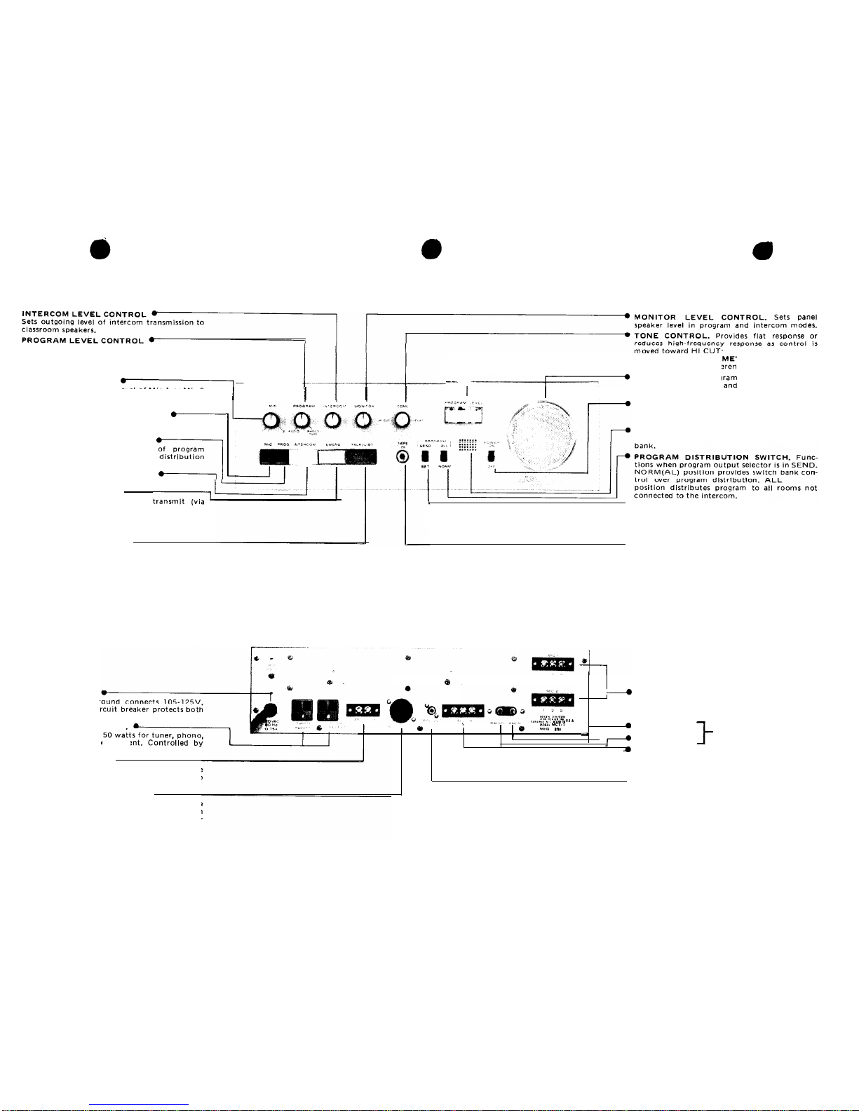
2. Program. Fader control sets level of radio or
phono/
tape program as indicated on output meter. May be
used with Microphone level control for program
mixing.
3. Intercom. Sets outgoing level of intercom transmis-
sion to room speakers.
4. Monitor. Sets panel speaker level in program and
intercom modes.
5. Tone. Provides flat response or reduces high-fre-
quency response as control is moved toward HI CUT.
PROGRAM OUTPUT METER. Color-coded to clearly
display 25 V reference level.
PROGRAM SWITCHES
1.
Program Distribution. Functions when program
output selector is in SEND.
NORM(a1)
position pro-
vides switchbank control over program distribution.
ALL position distributes program to all rooms not con-
nected to the intercom.
2. Program Output. SEND position enables program
distribution switch. SET position disconnects program
output from load for monitoring or presetting prior to
distribution. Does not offset intercom functions. The
program output switch should not be left in the SET
position. Once adjustment is made, switch should be
returned to SEND position.
SWITCH BANKS
MODEL SBS SWITCHBANK. Standard consolettes
are equipped with one or two Model SBS Switchbanks.
Each switchbank has 25 three-position lever switches
for connecting individual rooms to the system. Each
switch functions as follows:
A
-
(Up position)
-
Connects classroom speaker to
program channel for distribution of microphone, radio,
or phono program.
0
-
(Center position)
-
Disconnects classroom speaker
from system, except when consolette is operating in
Emergency mode.
C
-
(Down position)
-
Connects classroom speaker to
intercom channel.
MODEL SBL SWITCHBANKS (OPTIONAL). If
the system is equipped with an optional light-annunci-
ator call system, the consolette switchbanks will have
four-position lever switches. These switches operate
exactly as those in the Model SBS Switchbank, except
that there is a “B” (top) position of the switches which
is not used. If a switch is placed in the “B” position, it
functions exactly the same as in the “A” position.
OPERATION
NOTE
Before attempting to operate for the first
time after installation, check all input and
output connections and make certain the
consolette is connected to a power outlet.
TO TURN
CONSOLETTE-ON
Set POWER ON-OFF switch to ON position.
TO DISTRIBUTE MICROPHONE
PROGRAM
Move program output switch to SET position. De-
press MIC function switch. Select microphone level with
MIC fader control knob according to
contro1
panel
speaker volume and/or reading on PROGRAM LEVEL
output meter. When appropriate level is reached, dis-
tribute program by moving program output switch to
SEND position. Select either NORM for Switchbank
control over distribution or ALL for distribution to all
stations not connected to the intercom. (May be used in
conjunction with PROGRAM level control for program
mixing).
TO DISTRIBUTE RADIO/PHONO-TAPE
PROGRAM
Move program output switch to SET position. De-
press PROG function switch. Select level of radio/
phono/tape
program with PROGRAM fader control
knob according to control panel speaker volume and/or
output meter reading. Distribute program by switching
program output to SEND position.
To distribute output from a tape recorder, connect
the 2-conductor phone plug from the tape recorder to
TAPE IN jack on the control panel and follow pro-
cedure outlined above. Phonograph input will be auto-
matically disconnected.
TO OPERATE ALL-CALL FUNCTION
Move program output switch to SEND position.
Move program distribution switch to ALL position.
Program is transmitted to all stations regardless of posi-
tion of station selector switches. (Note: Disconnect in-
tercom function; stations connected to the intercom will
not be affected).
TO COMMUNICATE WITH SELECTED
STATIONS
TO SEND. Depress INTERCOM function switch.
Select station to be contacted on switchbank panel.
Depress TALK/LIST switch to send; release switch to
monitor. Intercom level control should always be left at
the setting for normal transmission to room speakers.
(Note: does not affect program distribution to other
stations).
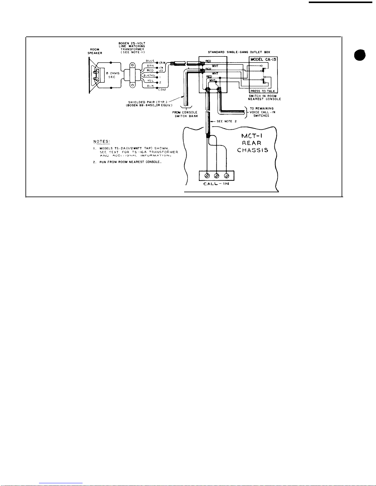
TO RECEIVE. If a voice call-in system is installed,
the station operator makes contact over the intercom
channel via the station speaker and CA-13 call switch,
and identifies his or her station. To respond to call,
select station on switchbank and depress TALK/LIST
-6-