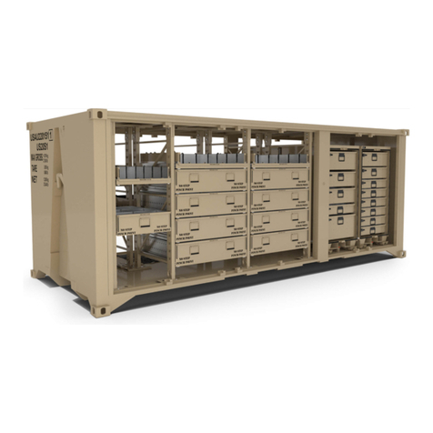
BOH Enviromental FPU-8-2 User manual

BOH-PM-13-2 © 2016 BOH Environmental LLC
Chapter 2 Rev. 0.01
FPU®SYSTEMS OPERATION MANUAL
BOH OFFICE MODULE
(INCLUDING REPAIR PARTS & SPECIAL TOOL LIST)
BOH FPU Field Pack-up Units
CHAPTER 2
OPERATOR INSTRUCTIONS

BOH-PM-13-2
Chapter 2 Rev. 0.01
This page was intentionally left blank

0007 00
BOH-PM-13-2
Chapter 2 Rev. 0.01 0007 00-1
OPERATOR INSTRUCTIONS
FPU®SYSTEMS OPERATION MANUAL
BOH OFFICE MODULE
(INCLUDING REPAIR PARTS & SPECIAL TOOL LIST)
BOH FPU Field Pack-up Units
PREPARATION FOR MOVEMENT AND TRANSPORT
Prior to moving the office module either by forklift or within a container, all internal and external
components must be properly secured. These tasks include, but are not limited to, the following:
•Lowering the roof height as necessary to fit in transport vehicle
•Securing office equipment utilizing ratchet straps provided on upper shelf
•Securing jack assembly components
•Retracting HVAC unit
•Securing both desk chairs to desk utilizing restraint straps provided
Fork Pockets
The Office Module is provided with fork pockets in the rear and both sides of the container to facilitate
lifting, positioning and loading of the module on FPU containers, transport vehicles and site locations. The
office module must be loaded into the FPU container using the rear fork pockets (1) with the door facing
out the side of the container. The side fork pockets (2) are typically used for positioning of the office
module once outside the container even though the rear fork pockets could be used for this purpose as
well.
CAUTION
The office module must be loaded into the FPU-8 or 8-foot section of the FPU-20 container using the rear
fork pockets which will orient the office module with the door facing out the side of the container. The
office module feet are designed to fit in some, but not all, of the available foot pads set in the container
floor cradle. Failure to load the office module in this orientation may result in damage to the container
and/or office module. This configuration also allows access into the office module when loaded inside the
container.
Module Rear
2
2
Module Front (Left)
Module Front (Right)
1
Office Module tare weight 3,500 lb.

0007 00
BOH-PM-13-2
Chapter 2 Rev. 0.01 0007 00-2
Positioning Office Module from the transport to the site
WARNING
Ground guides and the HME operators must maintain direct line of sight and
insure that personnel are clear of the office module during this operation.
Overhead power lines and obstructions can cause serious injury or damage to property.
Forklift operators, truck drivers and ground guides should always clear overhead when
loading, unloading the BOH Office Module.
CAUTION
The Office Module should only be lifted by the fork pockets provided on the left side, right side or rear, never from the
front.
DIRECT LINE OF SIGHT
GROUND GUIDE
GROUND GUIDE
DIRECT LINE OF SIGHT
Office Module

0007 00
BOH-PM-13-2
Chapter 2 Rev. 0.01 0007 00-3
Office modules may be secured within the FPU-8-2 and FPU-20-1 and 20-2 by means of the fixed floor
cradles and module locking arms (2). They may also be secured within the FPU-8-4 and FPU-20-3 by first
inserting removable cradles to the floor of the containers in order to provide the foot pads (1) and locking
arms (2).
CAUTION
Verify that the office module is properly seated and the red handle on the module-locking arm (2) is
pushed completely to its closed and locked position.
8-4 / 12-3
8-2 / 12-1
FPU 20-3
FPU 20-1 & 2
2
1

0007 00
BOH-PM-13-2
Chapter 2 Rev. 0.01 0007 00-4
Setup and Preparation
When used outside an FPU container, the Office Module must be placed on a level site to stabilize the
module and permit a level working environment.
1. Inspect the site and remove rocks roots and debris that would prevent the module
from being placed on a firm level site.
2. Locate the Office Module within proximity of electrical and communications service
connections at the rear of the container.
END OF WORK PACKAGE

0008 00
BOH-PM-13-2
Chapter 2 Rev. 0.01 0008 00-1
OPERATOR INSTRUCTIONS
FPU®SYSTEMS OPERATION MANUAL
BOH OFFICE MODULE
(INCLUDING REPAIR PARTS & SPECIAL TOOL LIST)
BOH FPU Field Pack-up Units
OPERATION OF OFFICE MODULE
ENTRANCE DOOR OPERATION
The office module entrance door consists of an upper and lower door section which swing and lock
independent of each other to allow for the raising and lowering of the roof section.
Upper Door
The upper door is hinged to the roof section and overlaps the front of the lower door, which is hinged to
the lower main body of the office module. The upper door is lockable with a separate set of keys (1) as
the lower door section. The upper door handle is oriented horizontally along the top of the door with a
release button catch (2) located on both sides of the door. The door locks from the inside by twisting a
thumb lever (3) clockwise.
A spring-loaded chain assembly (4) prevents the upper door from swinging freely open. Since the upper
door overlaps the lower door, the upper door then prevents the lower door from also swinging freely open.
2
1
3

0008 00
BOH-PM-13-2
Chapter 2 Rev. 0.01 0008 00-2
Lower Door
The lower door is the larger door of the two and includes a two-point lock system and separate set of
keys (1). The top lock can be unlocked from the inside simply be pulling the handle. The bottom lock acts
as a deadbolt lock (2) and can be locked from the inside by twisting the red thumb lever clockwise.
END OF WORK PACKAGE
1
2

0009 00
BOH-PM-13-2
Chapter 2 Rev. 0.01 0009 00-1
OPERATOR INSTRUCTIONS
FPU®SYSTEMS OPERATION MANUAL
BOH OFFICE MODULE
(INCLUDING REPAIR PARTS & SPECIAL TOOL LIST)
BOH FPU Field Pack-up Units
OFFICE MODULE ROOF
HEIGHT CONFIGURATIONS
The BOH Office Module provides the unique capability of raising and lowering the roof of the module to
various heights depending on whether the module is to be housed inside an FPU container, stand-alone
outside the container or per the preference of the user.
There are 4 height positions available, as evidenced by the different hole adjustments available on the
roof elevating lock assembly (5):
1. The 1st and shortest position (1) is the most compact option and requires the least amount of
volume within a container. This position does not allow for the HVAC system to be extended into
its usable position since the module roof overlaps the back of the HVAC unit. This position is not
recommended for use as a full-time office facility and should only be used for transit purposes.
*Internal Ceiling Height = 64”
CAUTION
The HVAC system shall not be operated in the retracted position as this will cause overheating and
damage to the HVAC system.
1
2
3
4
Roof Elevating
Lock Assemblies
(3 total)
Front Wall
Rear Wall

0009 00
BOH-PM-13-2
Chapter 2 Rev. 0.01 0009 00-2
2. The 2nd position (2) can be used within an FPU-8 or FPU-20 series container should the customer
desire this height.
*Internal Ceiling Height = 70”
3. The 3rd position (3) can be used within an FPU-20 series container should the customer desire
this height.
*Internal Ceiling Height = 74”
WARNING
Should the customer use the office module unit within an FPU container, both sides of the container shall
remain open and free of obstructions at all times. Failure to do so will damage the HVAC equipment and
may result in injury or death.
4. The top position (4) shown provides the tallest configuration but is only for use outside an FPU
container.
*Internal Ceiling Height = 84”

0009 00
BOH-PM-13-2
Chapter 2 Rev. 0.01 0009 00-3
ROOF HEIGHT ADJUSTMENT
The BOH Office Module provides a jack assembly and roof elevating lock assemblies to safely and
properly lift the module roof to the desired height once the module has been transported to its deployed
location.
Jack Assembly Storage
The office module provides designated storage locations for the jack assembly within the module. The
jack base assembly (1) is stored along with the hat (top) assembly (2) in the metal sleeve (3) adjoining
the storage cabinet (4). The hat assembly center post rests within the notch cut out in the sleeve. The
base assembly then rests directly behind and on top of the hat assembly as shown below.
3
2
1
4

0009 00
BOH-PM-13-2
Chapter 2 Rev. 0.01 0009 00-4
The jack device and main subassembly (1) is secured within the office module against the wall opposite
the desk by two wall brackets (2). These brackets include a spring-loaded knob (3) that secure to the
main subassembly by locking into two designated holes (4) in the side of the subassembly. The
subassembly can be removed from these brackets by a simple pull and twist of the knobs until they lock
in the out position (5).
Once the main jack subassembly, base assembly and hat assembly have been removed from their
storage locations, the complete jack assembly can be connected.
Pull, then twist
to lock out

0009 00
BOH-PM-13-2
Chapter 2 Rev. 0.01 0009 00-5
Procedure for Raising the Roof
WARNING
The Pop-up roof component of the office module is held in place and positioned by the 3 roof elevating
lock assemblies found inside the container. While it is possible for the roof to be separated from the main
bottom component of the office module, it is not recommended this be performed by anyone other than
the manufacturer.
1. First, remove the chairs from the office module and any other equipment which may interfere with
the jack operation.
2. Position the jack base on the floor directly beneath the yellow and black sticker on the ceiling
which reads “PLACE JACK HERE.”
3. Insert the hat assembly on the end of the main subassembly opposite the white end. For proper
orientation, position the hat assembly on the subassembly so the two horizontal posts on the hat
assembly are perpendicular to the direction of the jack crank handle.
4. With the base assembly pins removed, insert the main subassembly on the jack base. For proper
orientation of the completed assembly, position the main subassembly in the base where the jack
crank handle is pointing toward the wall opposite the desk.

0009 00
BOH-PM-13-2
Chapter 2 Rev. 0.01 0009 00-6
5. Insert the base assembly pins and lock.
6. Once all jack assembly components are secured, begin operation of the jack. To properly operate
the jack, first move the bottom lever (1) to the up position. Then begin cranking the jack handle
(2) in a downward motion. This will enable the jack carriage to climb up the toothed jack bar thus
extending the height of the jack assembly.
7. Once the jack assembly hat reaches near the ceiling and prior to making contact, ensure the hat
assembly is centered on the ceiling sticker with the two hat posts oriented perpendicular to the
black stripe on the sticker and parallel to the adjacent light fixture.
8. Continue jacking until solid contact is made between the hat assembly and the ceiling.
WARNING
Ensure the completed jack assembly is centered on the sticker and is in a straight vertical position.
Failure to comply could result in damage to equipment, injury or death.
9. Pull the lanyard pins from the side of the roof elevating lock assemblies.
10. Pull and twist the spring-loaded knobs from the front of the roof elevating lock assemblies until
the knobs are locked in the out position. The internal post and external casing of the lock
assemblies should each have holes in alignment.
WARNING
Ensure the pins have been removed and knob is disengaged and locked in the out position before
jacking. Failure to comply may cause the roof connecting bracket and lock assembly post to separate,
which may cause damage to equipment and make the roof unstable.
11. Continue jacking until the internal post of the lock assemblies have moved up and the hole is no
longer visible.
12. Twist the knobs on the lock assemblies to unlock which will allow the knob to press against the
internal post and act as a failsafe.
13. Proceed with jacking until the knobs engage the next hole position.
14. Repeat steps 10 through 13 until the desired roof height is reached. Then continue to step 15.
1
2

0009 00
BOH-PM-13-2
Chapter 2 Rev. 0.01 0009 00-7
CAUTION
Under no circumstances shall the roof be extended past the 4th hole position. Failure to comply may
cause damage to the roof elevating lock assembly and may make the roof and jack unstable. Any
maintenance requiring the removal of the roof shall be coordinated directly with the manufacturer.
15. Lock the lanyard pins in the designated holes in the side of the lock assembly casing.
16. Once all 3 elevating lock assemblies have been secured at the desired height, the operation to
lower the jack can commence. To properly retract the jack assembly, first move the bottom lever
(1) to the down position. Then begin cranking the jack handle (2) until the hat assembly is no
longer secured against the ceiling. The jack assembly can then be fully retracted by either
cranking all the way down or by pulling the quick release lever (3) located just below the jack
handle.
WARNING
Before pulling the quick release lever (3), always crank down the ceiling first to disengage the hat
assembly from the ceiling and ensure the ceiling is secured by the elevating lock assemblies. Failure to
comply could result in serious injury or even death.
17. Disassemble the jack assembly components and reposition them back in their designated storage
locations.
3
1
2

0009 00
BOH-PM-13-2
Chapter 2 Rev. 0.01 0009 00-8
Procedure for Lowering the Roof
1. Repeat steps 1 through 8 from the Raising procedure to secure the completed jack assembly
against the office module ceiling.
2. Pull and twist the spring-loaded knobs from the front of the roof elevating lock assemblies until
the knobs are locked in the out position. The internal post and external casing of the lock
assemblies should each have holes in alignment.
3. Begin cranking the jack down until the internal post of the lock assemblies have moved down and
the hole is no longer visible. See Raising procedure for crank operation.
4. Twist the knobs on the lock assemblies to unlock which will allow the knob to press against the
internal post and act as a failsafe.
5. Proceed cranking the jack down until the knobs engage the next hole position.
6. Repeat steps 2 through 5 from this section until the desired roof height is reached. Then continue
to step 7.
7. Lock the lanyard pins in the designated holes in the side of the lock assembly casing.
8. Once all 3 elevating lock assemblies have been secured at the desired height, the jack assembly
can be fully retracted. See Raising procedure for crank operation.
9. Disassemble the jack assembly components and reposition back in their designated storage
locations.
END OF WORK PACKAGE

0010 00
BOH-PM-13-2
Chapter 2 Rev. 0.01 0010 00-1
4
1
3
2
5
OPERATOR INSTRUCTIONS
FPU®SYSTEMS OPERATION MANUAL
BOH OFFICE MODULE
(INCLUDING REPAIR PARTS & SPECIAL TOOL LIST)
BOH FPU Field Pack-up Units
ELECTRICAL SYSTEM
Electrical and Communications Connections
The Office Module is provided with a communication connection box (1), a 120V outlet (2) with protective
weather cover and connection cable (3), cable pass-through (4) and external ground lug (5).

0010 00
BOH-PM-13-2
Chapter 2 Rev. 0.01 0010 00-2
Establishing Power Supply
The Office Module supplies an electric adapter cord and 30A 120V outlet to connect to electrical supply
source.
1. Before any electrical connections are made, enter the Office Module and ensure the main
circuit breaker and all the circuit breakers are turned off. Also ensure the main power source
has been turned off.
2. Establish a grounded connection at the electrical supply source.
3. Insert angle plug cord (yellow end) into office module.
4. Connect the white end of the cord to the power source (extension cord likely required).
5. Turn on the main power source. Then turn on all office module circuit breakers.
WARNING
Ensure all circuit breakers and the main power source is switched off before making electrical
connections. Ensure the proper cable connectors are installed by a certified electrician Army
MOS 21R and match the power source. An electrical ground must be established first to prevent
electrical shock to personnel. Consult ARMY TM 5-811-3 Chapter 2 and MIL-HDBK-633A.
Turn off all breakers
before connecting
power source

0010 00
BOH-PM-13-2
Chapter 2 Rev. 0.01 0010 00-3
Electrical Wiring Diagram

0010 00
BOH-PM-13-2
Chapter 2 Rev. 0.01 0010 00-4
3
2
4
7
5
1
6
Establishing Communication Lines
The Office Module supplies 4 sources of communication lines: dual Cat-3 (telephone) (1), Cat-5 (internet)
(2), coaxial cable (3) and dual WF-16 field cable (4). The internal connection side of the communication
box is pre-run for Cat-3 and Cat-5 through raceways (5) to designated user connection plugs. Dual Cat-5
plugs (6) are located above the upper shelf, and dual Cat-3 plugs are located below the desk adjacent to
a dual electric outlet. A Netgear Ethernet switch (7) is provided to supply the dual Cat-5 connection. The
Ethernet switch has a designated electrical outlet (labeled) below the breaker box.
.
External Side
Internal Side
This manual suits for next models
4
Table of contents
Other BOH Enviromental Storage manuals
Popular Storage manuals by other brands

Nexsan
Nexsan BEAST BT60 Removal and Replacement Guide
Supero
Supero AOC-CTG-i2S user guide
Simplay3
Simplay3 Easel 21707 quick start guide
Arrow Storage Products
Arrow Storage Products LWEG86AN Owner's manual & assembly guide
SNOWJOE
SNOWJOE AUTOJOE ATJ-CTSO-BLK manual

Seagate
Seagate Momentus 5400.1 Cruise ST93012A-AM product manual

HP
HP 11180A Operating and service manual

Hitachi
Hitachi Freedom Storage Lightning 9900 V series Configuration guide
Qualstar
Qualstar XLS Series Technical & service manual
Oracle
Oracle storagetek sl150 Library Guide

Qsan
Qsan XCubeSAN XS5216D Quick installation guide
Iomega
Iomega eGo 33832 quick start guide
