WiebeTech LLC
R T 5 F u l l U s e r ’ s M a n u a l - 4 -
write data on several drives. Up to five disk drives can be connected to each RAID controller. It
supports the ATA/133 standard, which is backward compatible with earlier ATA standards.
1.2 RAID subsystem Controller Board
The controller has an IDE controller which supports an ATA/133 host interface section, and a
drive interface to five Ultra ATA/133 hard drives. The IDE controller supports a XOR engine
parity generator/checker, one RS-232 interface for system management (Remote Control and
Local Monitor), and an interface to a display/operation panel. Within the array, the controller
acts as a bridge between host IDE channels and drive IDE channels via Ultra ATA/133 bus, and
implements the RAID function.
1.2.1 Cache Memory Subsystem
The RAID subsystem new high-performance architecture comes from its low power 64-bit RISC
processor, a 66MHz/32-bit PCI, and 64-bit memory architecture. The data flow at 66MHz/32-bit
PCI bus and 64-bit ECC SDRAM makes its high data throughput more than sufficient for an
entry-level or high-end PC. Data can be transferred between the controller and the drives
through a high-speed 66MHz/32-bit path at a burst rate up to 266MB/sec. The system's overall
performance can support up to 133MB/second per ATA drive channel. The RAID subsystem is
configured with 64 Megabytes of SDRAM cache on the controller board. The system supports
Write-Through and Write-Back cache. In Write-Through Cache, the controller sends a data
transfer completion signal to the host operating system when the data is written to the ATA
Drive. This caching method is considered more secure, but a Write-Through cache has a lower
performance than Write-Back cache. In Write-Back Cache, the controller sends a data transfer
completion signal to the host operating system when the controller cache has received all the
data in a transaction. If a power failure occurs before the data is written to the disk drives, data
in the cache memory will be lost. Therefore, it is recommended that a backup power source (for
example, UPS) be used when enabling the write-back caching mode option.
1.2.2 User Interface
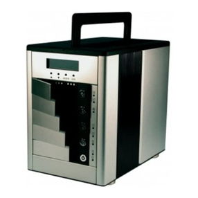
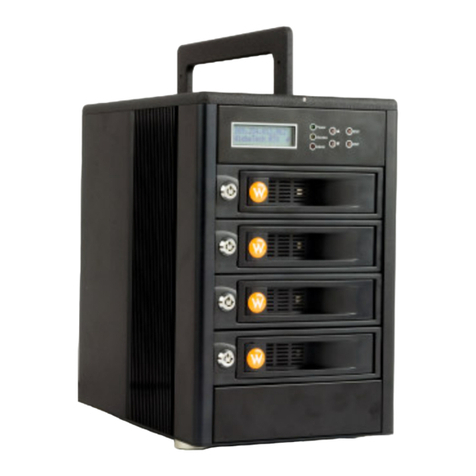
Manual configuration and monitoring can be done through the LCD front control panel. The
firmware also contains an embedded management program that can support the RS-232C
(Serial Console) port out-of-band management. The controller can use any of the interfaces to
simplify the setup and management of their associated disk drives. This out-of-band method is
a convenient platform-independent management utility. You can use this port to implement
Bootable CD VT-100, VT-100 Terminal and HTTP Proxy browser-based management utility.
1.2.3 Controller Firmware
The system provides RAID levels 0, 1 (0+1), 3, and 5 RAID configurations. It can be managed
either through the LCD control panel or by the system-embedded configuration utilities. Its high
data availability and protection derives from the following capabilities: Online Capacity
Expansion, Online RAID Level Migration, Logical Drive Capacity Extension, Array Roaming,
Global Online Spare, Automatic Drive Failure Detection, Automatic Failed Drive Rebuilding,
Disk Hot Spare, and Instant Availability/Background Initialization. The RAID subsystem firmware
is stored on the controller flash ROM and is executed by the RISC CPU. The firmware can also
be updated through the RS-232 port without the need to replace any hardware chips. During the
controller ROM flash process, it is possible for a problem to occur resulting in corruption of the
controller firmware. A corrupted firmware in the controller firmware would make the controller
inoperable and bring the system down. The Redundant Flash provides a unique redundancy
feature that helps ensure against controller availability. This reduces the risk of system failure
due to firmware crash. In addition to the stored programs in ROM, the NVRAM stores data on
