Bollhoff 4080 Tool User manual
4080 Tool
Visa, Mastercard, Discover & AMEX Accepted .Fax: 262.252.5033
CALL TODAY
800.236.3200
ISO CERTIFIED
info@cardinalcomponents.com

1
ENGLISH
TABLE OF CONTENTS
1.PNOITPIRCSEDLOOTI
3.PSEIROSSECCAII
3.PNOITAREPOLOOTIII
5.PECNANETNIAMVI
8.PSNOITULOSDNAGNITOOHSELBUORTV
I - TOOL DESCRIPTION
Tool function
The 4080 tool is intended to crimp RIVKLE®blind rivet nuts into previously drilled supports
or punched holes in the parent material.
Stroke installation
This tool allows crimping RIVKLE®items according to the stroke installation method
Features
- Installation capacity: RIVKLE®M3 to M12, steel (max. load: 21 kN at 6 bar)
mm7:ekorts.xaM-
- Operating pressure 5.5 bar min. to 7 bar max.
- Weight, equipped as M6: 2.6 kg
- Air consumption: 8 L
)A(Bd07<:levelesioN-
Dimensions
M3 M4 M5 M6 M8 M10 M12
Standard A 68 68 68 68 68 68 68
rod L 32 31 41 42 42 52 56
Commercial A 59 59 59 59 59
screw L 33 34 40 42 47
SAFETY: BEFORE ANY INTERVENTION ON THE 4068 TOOL, DISCONNECT THE COMPRESSED
AIR FITTING
Visa, Mastercard, Discover & AMEX Accepted .Fax: 262.252.5033
CALL TODAY
800.236.3200
ISO CERTIFIED
info@cardinalcomponents.com
N°1 N°2 N°1 N°2
M3 236 113 03 020 236 113 03 030376 113 03 020 376 113 03 030
M4 236 113 04 020 236 113 04 030376 113 04 020 376 113 04 030
M5 236 113 05 020 236 113 05 030376 113 05 020 376 113 05 030
M6 236 113 06 020 236 113 06 030376 113 06 020 376 113 06 030
M8 236 113 08 020 236 113 08 030376 113 08 020 376 113 08 030
M10 236 113 10 020 236 113 10 030376 113 10 020 376 113 10 030
M12 236 153 10 020 236 113 12 030
2
1+2+3+4 1* 2 3 4
M3 236 803 03 000CHC ISO4762236 113 03 030 236 803 03 040 236 803 03 010
DIN912 : M3 x 60
M4 236 803 04 000CHC ISO4762236 113 04 030 236 803 04 040 236 803 04 010
DIN912 : M4 x 60
M5 236 803 05 000CHC ISO4762236 113 05 030 236 803 05 040 236 803 05 010
DIN912 : M5 x 70
M6 236 803 06 000CHC ISO4762236 113 06 030 236 803 06 040 236 803 06 010
DIN912 : M6 x70
M8 236 803 08 000CHC ISO4762236 113 08 030236 803 08 010
DIN912 : M8 x70
ENGLISH
T)swercs01(020X0308632:* ab. 1
34000351632=5.oN61200308632=6+831+541.oN
Visa, Mastercard, Discover & AMEX Accepted .Fax: 262.252.5033
CALL TODAY
800.236.3200
ISO CERTIFIED
info@cardinalcomponents.com

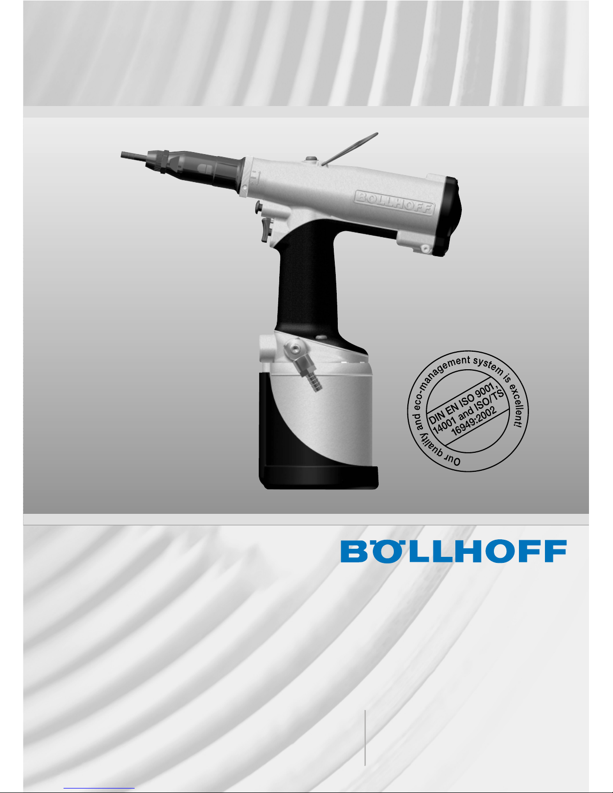
II - ACCESSORIES
Tooling for RIVKLE ®item installation with socket head cap screw mandrel (p. 12)
SOCKET HEAD CAP SCREW CHC DIN912
Screw replacement
- Loosen anvil locknut and unscrew anvil (2)
- Unscrew nose-piece (5)
- Fit screw (1) through washer (3), suitable for the required diameter (no washer for M8)
- Fit drive end piece (4) into screw (1) recess
- Slide the assembly into pull-out bush (7)
- Re-install nose-piece (5)
- Re-install anvil and locknut (2)
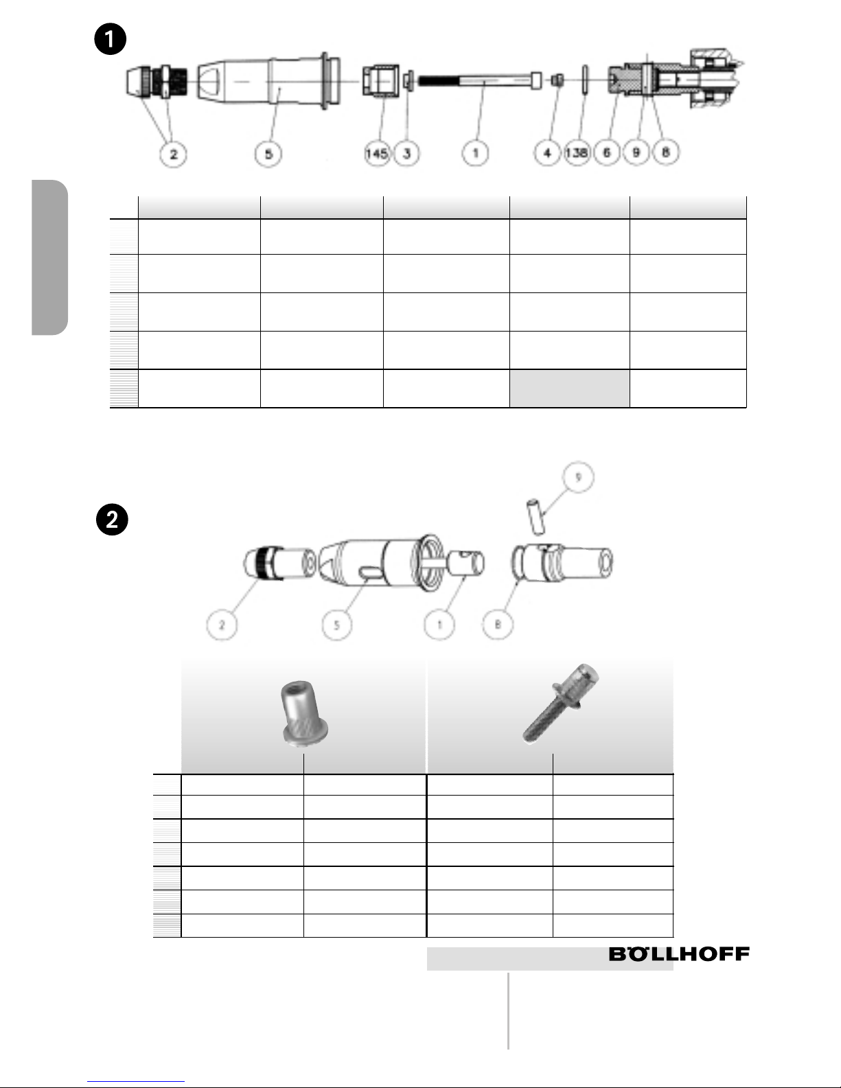
STANDARDS TOOLS
Setting tooling for RIVKLE ®or RIVKLE®stud (with special female mandrel) (p. 12)
If you already use an OPEN tool, the existing female mandrel can be re-used.
Tooling replacement (with special female mandrel)
- Keep nose-piece (5) in place; loosen anvil locknut, then remove anvil (2) and locknut.
- Drive out pin (9) by means of a drift without damaging retaining ring (8)
and release mandrel entirely (1).
- Re-install new mandrel (1) and t pin (9) again, ensuring that it is retained by retaining ring (8).
- Screw in nose-piece (5) again and torque to 15 Nm.
- Screw in new anvil (2) again inside nose piece and lock by means of locknut.
III - TOOL OPERATION
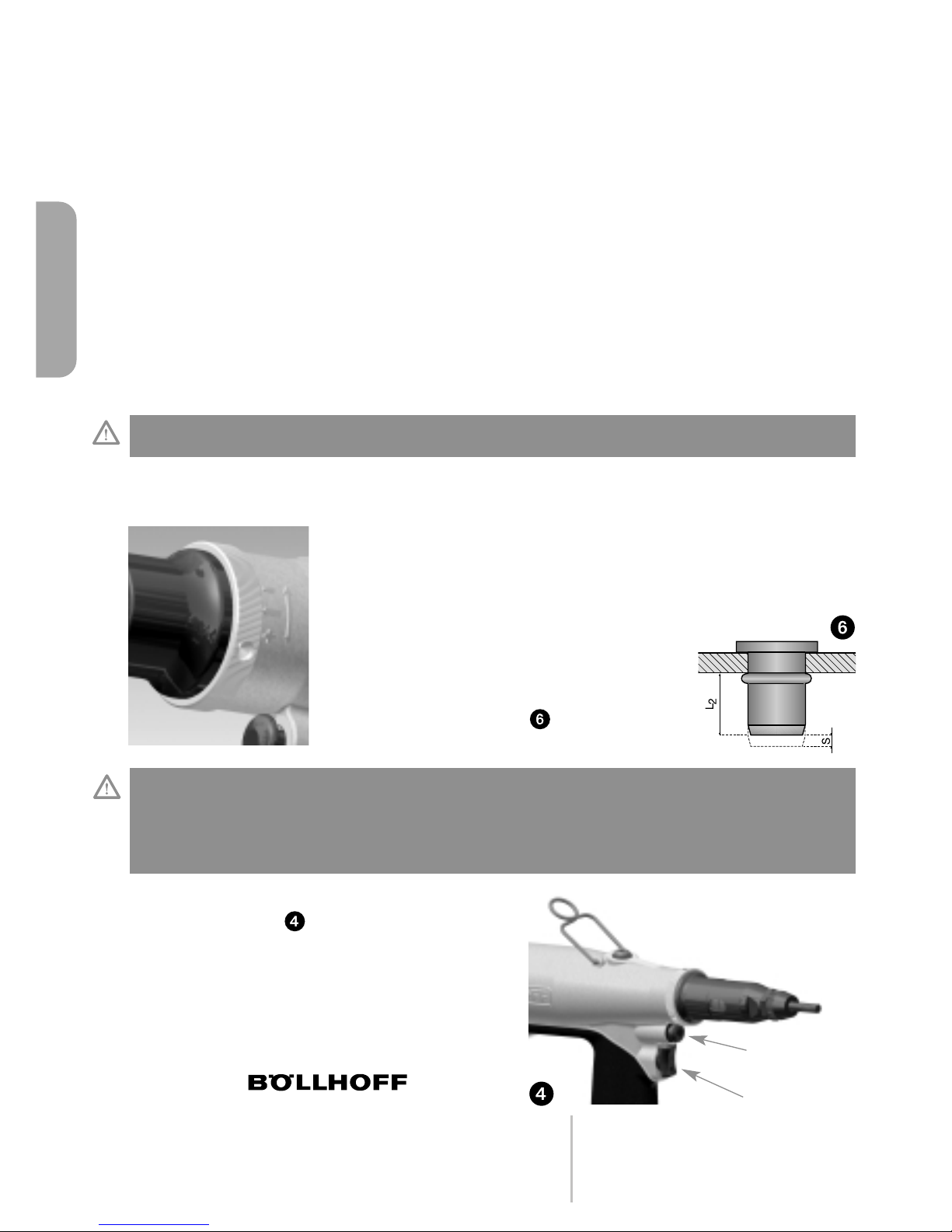
Anvil position adjustment versus mandrel
- Anvil position depends on RIVKLE®length before crimping.
- Adjust anvil position as indicated in gure 3.
- After adjustment, lock anvil locknut (2) to 10 Nm torque..
OPEN RIVKLE ®BLIND RIVKLE®
Flush-mounted mandrel at RIVKLE®end Mandrel at 1 turn from thread bottom
3
ENGLISH
Visa, Mastercard, Discover & AMEX Accepted .Fax: 262.252.5033
CALL TODAY
800.236.3200
ISO CERTIFIED
info@cardinalcomponents.com
4
Connection to compressed air system
All tools are air-driven, at an optimum pressure of 6 bar. We recommend the use of air treatment
units including lubrication, ltering and pressure control on the compressed air supply system.
These devices must be installed at maximum 3 metres from the tool in order to ensure optimum
tool service life and minimum maintenance.
All air hoses MUST MANDATORILY FEATURE AN INNER DIAMETER OF AT LEAST 6.4 mm
Operating method
The tool can be operated in all positions, either carried in hand or suspended.
Operating procedure
- Connect the air supply to the tool.
- Oer up the RIVKLE®onto the mandrel. A slight pressure will start the motor
and automatically initiate RIVKLE®screwing in onto the nose-piece, then motor shutdown
(Push-Pull system).
- Introduce the RIVKLE®into the hole in intended application.
- Press the trigger and keep depressed until the device is fully released.
This action both crimps the RIVKLE®into the intended application
and releases it from the mandrel (by unscrewing).
- Check that air system pressure is set between 5,5 and 7 bar.
- Before crimping, adjust stroke to 0 by turning the adjustment ring
to minimum position in (-) direction.
- Gradually increase crimping stroke by turning the adjustment ring
towards (+). This adjustment ring features
3 index marks. 1/3 turn corresponds to 0.5 mm
(1 complete turn = 1.5 mm).
- At each step, test RIVKLE®crimping quality,
until obtaining optimum crimping.
- Optimum crimping (dimension s) is indicated
in your RIVKLE®catalogue
Crimping pressure adjustment
Unscrewing button
In case of unscrewing problem, the 4080 tool is
equipped with an unscrewing control button on
top of the crimping trigger. To start unscrewing,
press unscrewing button (1), then press crimping
trigger 2 at the same time.
CAUTION: THE TRIGGER MUST BE KEPT DEPRESSED FOR THE ENTIRE CYCLE. RELEASING THE
TRIGGER WOULD RESULT IN FAULTY CRIMPING.
CAUTION: WHEN DELIVERED, THE TOOL IS DELIBERATELY SET TO 0 MM STROKE. THEREFORE, IT
IS MANDATORY TO ADJUST THE DEVICE WHEN PUTTING INTO SERVICE.
EXCESSIVE STROKE CAN DAMAGE RIVKLE ®TAPPED THREADS, AS WELL AS THE MANDREL, OR
PREVENT MANDREL UNSCREWING.
WHEN CORRECT CRIMPING IS OBTAINED, RECORD THE POSITION OF THE INDEX MARK ON THE
ADJUSTMENT RING, FOR REFERENCE.
ENGLISH
2
1
Visa, Mastercard, Discover & AMEX Accepted .Fax: 262.252.5033
CALL TODAY
800.236.3200
ISO CERTIFIED
info@cardinalcomponents.com
5
IV - MAINTENANCE
General maintenance
YCNEUQERFNOITAREPO
Check that the installed tool corresponds to your RIVKLE ®At each adjustment
Check that tool crimping stroke is suitable for the selected RIVKLE®
yliadecnO.)tnemtsujdaerusserpees(
yliadecnO.deriuqersaecalper;noitidnoclerdnamkcehC
Check that “screwing - crimping - unscrewing ” operations are
controlled by pressure exercised on the mandrel and the trigger, Once daily
without RIVKLE ®loaded.
Check that rst RIVKLE®is screwed in down to the anvil.
Always keep mandrel perpendicular to parent material. /
Lightly oil mandrel. Every 50 RIVKLE®crimped
After use, protect mandrel with a RIVKLE ®/
Occasionnal maintenance
The compressed air supply must be disconnected before any maintenance or removal operation.
Every 500,000 cycles, the tool must be entirely dismantled and all worn or damaged items
replaced.
It is also recommended to replace all items contained in the repair kits.
Any removal operation should be performed in good cleanliness conditions.
Maintenance kit
In order to facilitate maintenance, we recommend the use of special maintenance tools in order not
to damage your tool.
IMPORTANT NOTE: TOOL MAINTENANCE MUST BE ENSURED BY COMPETENT TECHNICIANS. THE
OPERATOR MUST NOT CARRY OUT TOOL MAINTENANCE OR REPAIR, UNLESS SUITABLY TRAINED
FOR THIS PURPOSE.
Oil level lling
- Disconnect compressed air supply.
- Remove upper oil lling threaded plug, It. 9, and screw It. 54.
- Using a mandrel, push back pneumatic piston It. 37
down to tank bottom, It. 36.
- Check oil level through port (It. 9), and ll as required,
to reach the lower section of the tapped port.
- Re-install threaded plug It. 9 with seal It. 10 & screw It. 54.
- Reconnect the compressed air supply and check the crimping
pressure after several cycles of the trigger.
- In case of insucient stroke, repeat the operations.
EXCLUSIVELY USE HYDROLUB H68 CONDAT OIL OR SIMILAR.
Repair kit N ° 236 155 00 220
Special maintenance tools Upon request
It. 9
It. 54
ENGLISH
/
5
Visa, Mastercard, Discover & AMEX Accepted .Fax: 262.252.5033
CALL TODAY
800.236.3200
ISO CERTIFIED
info@cardinalcomponents.com

6
Visa, Mastercard, Discover & AMEX Accepted .Fax: 262.252.5033
CALL TODAY
800.236.3200
ISO CERTIFIED
info@cardinalcomponents.com
ENGLISH

DESCRIPTION P/N
030563516321*gnirpS2
3 Receiver piston 1 236 153 65 002
4 Guide bush * 1 236 153 00 390
410003086321gniR5
6 Anti-extrusion ring * 1 236 153 65 112
701563516321*laeS7
611563516321wercs6M9
10 BS ring, 8 DIA. * 1 236 153 65 113
11 Thrust washer 1 236 153 65 104
430563516321*laeS21
13 Anti-extrusion ring * 1 236 153 65 111
14 Stroke stop 1 236 155 00 014
15 Pin, Ø 5100055163214
610005516321gniR61
210563516321evirD71
18 M10 screw 1 C95 101 51 010
19 Pull-out pin 1 C25 110 10 100
20 Retaining ring 1 C25 110 10 410
21 Pull-out bush 1 236 155 00 021
22 Nose-piece 1 236 155 00 022
23 Rear cover seal 1 236 155 00 023
24 Circlips ring, 44 mm DIA. 1 236 153 65 101
27 Spring washer 1 236 153 65 026
820005516322esoH82
920005516322wercs4M92
030005516322gulP03
501563516322*laeS13
301563516321*laeS23
33 Anti-extrusion ring * 1 236 153 65 110
34 Transmitter piston bearing 1 236 153 65 021
630005516321knaT63
801563516321*laeS83
901563516321*laeS93
40 Tank protection 1 236 803 00 064
220563516321gulpknaT14
911563516321retliF35
511563516321wercs8M36
73 Push-pull rod * 1 236 153 65 011
74 Plastic grip 1 236 155 00 074
570005516321*laeS57
670005516321*laeS67
770005516321*laeS77
78 Indexing bush 1 236 155 00 078
102005516321ydoB1E
E2 Cycle start trigger 1 236 155 00 202
E3 Unscrewing button 1 236 155 00 203
402005516321noinuriA4E
E5 Distributor valve 1 236 153 65 806
E6 Push-pull * 1 236 153 65 807
008563516321rotoM8E
E9 Cycle distributor valve 1 236 155 00 209
012005516321notsipriA01E
E11 Stroke adjustment ring 1 236 155 00 211
E12 Rear cover 1 236 155 00 212
022005516321tikriapeR02E
7
* items included
in repair kit
23615500220
ENGLISH
Qt.
Visa, Mastercard, Discover & AMEX Accepted .Fax: 262.252.5033
CALL TODAY
800.236.3200
ISO CERTIFIED
info@cardinalcomponents.com

PROBLEM
Damaged mandrel threads.
Dicult screwing/unscrewing
actions.
RIVKLE®threads
defective after installation.
RIVKLE®turns in the hole.
Device does not unscrew
at end of crimping stroke.
Screwing function inoperative.
No crimping stroke.
Tool mandrel spins continuously.
Unscrewing function inoperative
(device blocked on the part).
Tool stuck in the RIVKLE ®.
PROBABLE CAUSE
1 - Thickness to be crimped
incompatible with RIVKLE ®.
2 - Excessive crimping stroke.
3 - Device positioning incorrect
during crimping.
4 - Damaged pull-out rod threads.
1 - Damaged mandrel threads.
2 - RIVKLE®incompletely screwed
on mandrel.
3 - Excessive crimping stroke.
4 - Thickness to be crimped
incompatible with RIVKLE ®.
1 - Thickness to be crimped
incompatible with RIVKLE ®.
2 - RIVKLE®head not bearing
on anvil at the time of crimping.
3 - Insucient crimping stroke.
1 - Low compressed air pressure.
2 - Low oil level.
3 - Motor problem.
1 - No air supply to device.
2 - Push-Pull valve out of adjustment.
1 - Adjustment ring at minimum
position.
2 - Low oil level in tool.
1 - Push-Pull valve out of adjustment.
1 - RIVKLE®tapped threads
or mandrel threads damaged.
2 - Low oil level.
3 - Insucient air pressure.
SOLUTION
1 - Check crimping stroke range
in RIVKLE®catalogue.
2 - Repeat crimping test according
to instructions.
3 - Keep mandrel/tool perpendicular
to parent material.
4 - Replace mandrel as per instructions.
1 - Replace mandrel as per instructions.
2 - Adjust anvil position as per
instructions.
3 - Repeat crimping tests as per
instructions.
4 - Check crimping stroke according
to RIVKLE®catalogue.
1 - Check crimping stroke according
to RIVKLE®catalogue.
2 - Ensure that head is correctly
bearing, when screwing.
3 - Repeat crimping test as per
instructions.
1 - Check air supply pressure.
2-Fill oil level as per instructions
in § 5.
3 - Check motor rotation at no load.
1 - Check that compressed air
supply to device is ensured.
2 - Adjust Push-Pull valve per
instruction item.
1 - Adjust crimping stroke.
2 - Fill oil level.
1 - Adjust Push-Pull valve per
instruction item.
1 - To release the tool:
- position pin (9) to match an
aperture in nose-piece (5) and
drive pin out,
- unscrew anvil (2),
- release the tool.
2 - Fill oil level as per instructions
in § 5.
3 - Check air pressure.
V - TROUBLESHOOTING AND SOLUTIONS
Before any intervention, check oil level and air supply pressure (between 5.5 and 7 bar)
ENGLISH
8
Visa, Mastercard, Discover & AMEX Accepted .Fax: 262.252.5033
CALL TODAY
800.236.3200
ISO CERTIFIED
info@cardinalcomponents.com
Table of contents


