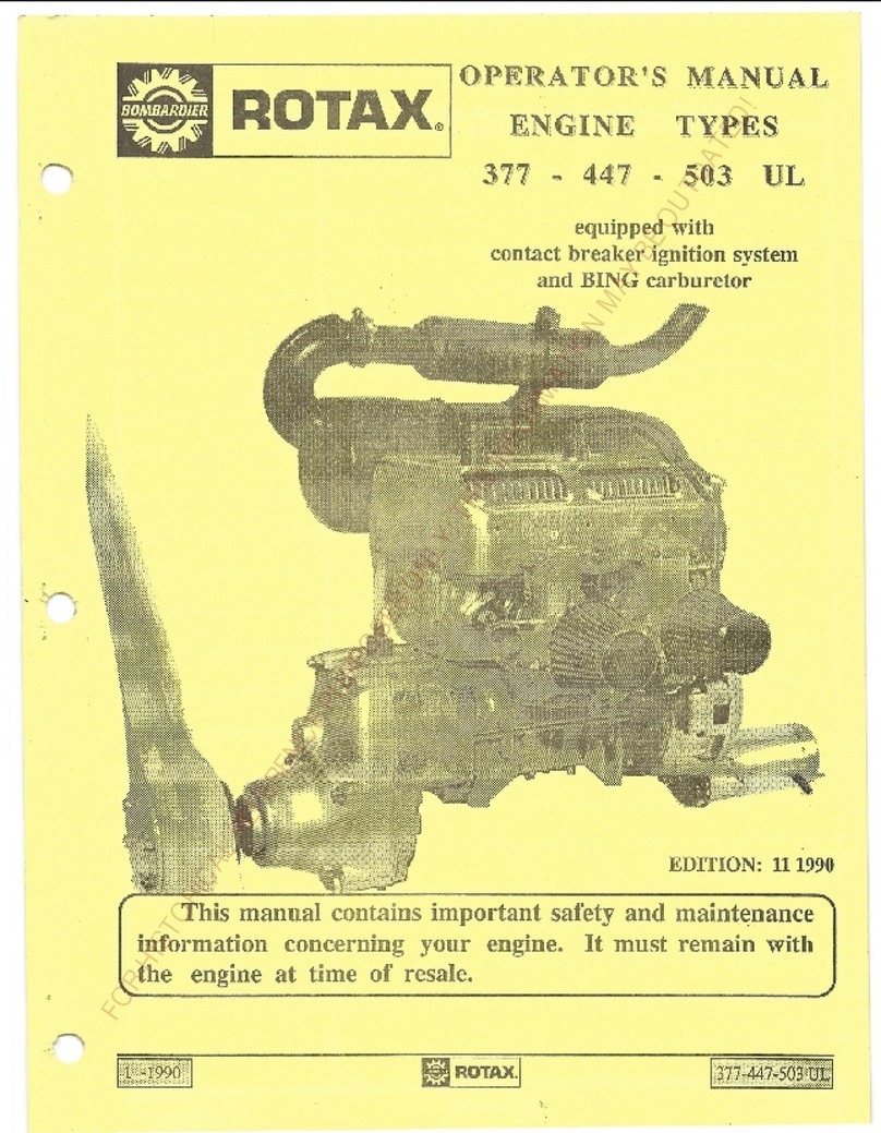
Bombardier-Rotax 462 User manual

·
.
OPERATOR
'
S
MANUAL
TYPE 462 ENGINES
EQU
I
PPED
WI
T
H
BOSCH CONTACT BREAKER
IGNITION SYSTEM AND
BING
CARBU
R
ErOR
Edition
0
4
BOMB
A
R
DIER-ROTAX
G
M
BH
MOTORENFABR
IK
A-4623
Gunsk
i
rchen
-
Au
s
tr
ia
Telefon
:
(07246)
27
1-
0
·
,
Tele
x:
255
46
brg
k a
Telegrammadresse:
Bom
b
rotax
G
un
skirc
h
en
1
988
FORHISTORICALREFERENCEPURPOSESONLY:THISINFORMATIONMAYBEOUTDATED!

,
'.
,"
~,
.1
'Q
'"..
'"
..
I
r
..
t,
'I
.-
•
•.
~
l'
:.
.
.( ,\,
,,.
.
'.
'I i
I
1
.I
.
.
-
.~
',
..
'"
'"
..
•
•
"
f,
,
.
,;
~
..
.
.
,
""
.,
"
•
.I.,
t'
r
-,
.
'I
...
•
•
,
.
~
"
;
I
"
•
.•
.-
•..
,
"
A.
•
r
.
'
.
"
I
..,
(
.
:.
~
"
·4
'':
••
'
..
'I
i
:r
J.
t
"
..
,..
.
..
.
.
.
'i
•
f
t'
"':
~.
•
"
"',.-.
"
..
,
..
.
.
"
f
!'~
~
.
""
.
,
,_:-
.•
r
..
,\.,
".
;
.
''',
: ,
I
rt
I
.
(
J
.
"
h
"
.'
,.
.;
..-
,
r
'
-
.•.
.-
c
"
FORHISTORICALREFERENCEPURPOSESONLY:THISINFORMATIONMAYBEOUTDATED!

-
1
-
Table
of
Contents
Page
2
3
4
6
7
8
9
10
11
.
.
12
13
14
16
18
20
21
22
Fuel/Fuel Oil
Mixture
Break-in
Procedure
Rotary
Valve
Adjustment
/
Carburetor
Starting
the
engine
/
Spark
Plug
Ingition
Unit
Adjustment
of
I
gnition
Timing
/
Pole Shoe
Gap
Wiring
Diagram
Ignition
Damping
Box
/
Wiring
Diagram
for
mounting
ignition
damping
box 866 572
Lighting
Circuit
Wiring
Diagrams
for
rectifier-regulator
866 080
Wiring Diagrams
for
rectifier
-
regulator
264
870
Rewind
Starter
/
Changing
the
starter
rope
Decarbonizing
/
Main
Torquing
Specifications
Fault-Tracing
-
Schedule
Liquid
-
Cooling System
Gear for
rotary
valve
and
liquid-cooling
pum
p
Mounting-,
Maintenance-
and
Safety
Instructi
on
s
for
UL
-
prop
gear
on
ROTAX
engine
types
377
-
447
-
503
-
462
-
532
24
Service Information
type
462
UL
-
Rotary
Val
v
e
Adjustment
25
Technical
Data
FORHISTORICALREFERENCEPURPOSESONLY:THISINFORMATIONMAYBEOUTDATED!

-
2
-
GENERAL
The
ROTAX engine
is
a
liquid-cooled
2-stro~~
engine.
Careful
and
extensively
tested~design and rugged
construction
as
well
as
.
the
use
of
.
high quality
parts
warrant
maximum reliability
and
durability. With proper maintenance and
care
and
with
the
use
of
suitable
fuel
and oil
the
engine
wilL
give
you
trouble-free
service for
many
years.
'_
,
The
ROTAX
design
~ncorporates
the
latest
technical
develop-
ments.
In
order
to
take advantage of
future
developm.ents
we
reserve
the
right
to
make modificat~ons
in
the
ROTAX
design
.without
notice.
FUEL
As
fuel
for
engine
type
462
UL
regular
gasoline, leaded
or
unleaded,
octane
number
not
below
RON
90
(or
MON
83)
is
prescribed.
Premium
gasoline
can
be
used,
too.
If
possible,
leaded
fuel
should
be used.
When
using
unleaded
fuel.
only
use
fuels
'
o~
recognized
brands.
When
lead
in
fuel
is
omitted,
alcohol (methanoL ethanoL isobutanol
etc
.
)
is
added
to
avoid
knocking. Due
to
the
water
absorption
of
the
highly
hygros~.o.pical
alcohols. the fuel
quality
cannot
be
maintained
over
a
long
period.
Further
the
alcohol
additive
causes
leaner
fu
~
air
mixture
(because
of
oxygene
in
alcohol)
resulting
in
general
i
)r
/
higher
engine temperatures.
A
higher
percentage
of
alcohol increases the
risk
of
vapour
lock due
to
higher
vapour
pressure
of
alcohol.
The
alcohol
percentage
must
not
exceed
10
%.
FUEL
-
OIL
-
MIXTURE
The
.
ROTAX
engine
is
operated
by
a
mixture of standard
grade
gasoline
and
-
Super
2-stroke
oil
the oil
lubricating
the
moving
engine
parts.
'
Mixing ratio
fuel
be
respected. oil
is 50
:
1;
this
mixing ratio
has
to
Too
much
oil
will
cause
carbon
deposits
on
the
spark
plug,
on
the
piston,
in
the
cylinder
ports
and in
the muffler
and
will
cause
problems.
In
addition,
the
piston ringsmay
stick.
I
f
too
little
oil
is
used_ lubrication
will
be
insufficien
t
,
the
pistons
will seize
and
the
bearings will
be
damaged.
FORHISTORICALREFERENCEPURPOSESONLY:THISINFORMATIONMAYBEOUTDATED!

-
3
_
-
BREAK-IN
PROCEDURE
The
break-in
has
to
be
perfor~ed with
the
engine
in
the
nir-
frame,
loaded
with
the
propeller. Tishten
the
plane
t
.
o
the
gr-ound
and run the
engine
ac
cording
to the follmdng graph:
Engine
rop
.m·l
.:x
1000
Full
10 15
sec sec
20 30
sec
sec
j
2
min
min
2
min
1
-
-
----- ---
-
_-
--- ---- r--
-
-
-
.--
;
-
1
,-
1
5
5
5
5
5
5
5
5
5
-
_
_
_.
i..
1
1
1
1
.,
1
1
1
2
·1
...
tl
I
I
•
,
-'
I I
-
I
•
1
T I
.
5,5
5
4,,5
4
3,,5
3
'r
2
"
o
10
20
30
40
50
60
Time
(min)
After
this
procedure
the
idle
has to
be
adjusted.
Then
sh
o
rt
take-offs
can be
conducted
.
.
FORHISTORICALREFERENCEPURPOSESONLY:THISINFORMATIONMAYBEOUTDATED!

Rotary
Valve Adjustment
Installation:
To
correctly install
the
rotary valve disc proceed
as
follows:
-
Turning
crankshaft counter-clockwise
(drive
pulley
side),
bring
.
magneto
side
piston
to
Top
Dead Center using
a
T.D.C
o
gauge.
-
.
-
Position
the
rotary valve disc on
gear
to
have edges
as
close
as
possible
to
the
marks.
NOTE:
The
rotary valve disc
is
asymmetrical, therefore,
at
assembly
try
positioning each
side of
disc on gear
to
de:termine
best
installation position.
See
also page
no.
24
CARBURETOR
The
BING
carburetor
is
a
piston
type
carburetor with
float
chamber
.
The
carburetor
can
be
adjusted
by
jets
and
adjusting
screws.
Changing of jets should
only
be
done
by
a
specialist
or
after consulting
the
engine manufacturer.
The air
-
fuel
mixture
at
idle
speed
is
adjusted
by
the
air
adjusting
screw
(see
ill. no.
28).
The
idle
r.p.m.
is
adjusted
by
the
carburetor piston adjust-
ment
screw
(ill.
no.
30).
Note:
The
carburetor
must
be
in
an
exact right
angle
position
i
n
relation
to
the
crankshaft
in
both views
from
top
and
from
the
intake
side
to
ensure
an
equal
mixture
distri-
bution
to
both
cylinders.
Take
care that
end
of
both
ventilation
tubes
(ill. no.
31)
are
protected
from
FORHISTORICALREFERENCEPURPOSESONLY:THISINFORMATIONMAYBEOUTDATED!

·
.
I
,
.
,
.
.
BING-Carburetor
40~
T
~
41
42
43
-
5
-
-
44
~---29
~30
21
24
25
5
0-
4
9-
FORHISTORICALREFERENCEPURPOSESONLY:THISINFORMATIONMAYBEOUTDATED!

6
-
STARTING
THE ENGINE
On
cold
engine
use
choke.
Don't
set
throttle
.
Start
the
engine.
After
the
first
ignitions
open
throttle
and shortly
after
close
choke
.
Attention:
Throttle
opening
reduces
the
effect
of
,the
choke.
If
the
engine
is
started
too
long
with
the
'
choke,
,
the
engine
gets
flooded with
fuel.
If
this
.
nappens ;
the
_
_
apar-k
v
p.Lug
s
have
to
be
unscrewed,
cleaned,
dried
and
the
engine has
to
be
started
(cranked
through)
several
times.
If
the engine still
does not
start,
see
chapter
"Fault
Tracing
Schedule".
SPARK
PLUG
If
the
engine
fails
to
start
or
operates
only on
one
cylinder,
_
it
should be
checked whether
the
ignition wiring
is
disconnected
from the
spark plug protectors
or
from
the
spark
plugs.
Then
the
condition
of
the
spark
plugs has
to be checked (bridged
between
the
electrodes,
oily,
sooty
etc.).
If
the
spark
plug
heat
range
and the
carburetor calibration
are
correct,
the spark
plugs look brownish.
'
With
too
high heat
range
(cold
plug)
and
too
rich carburetor
<
,
calibration they look
black
and
sooty.
With
too
low
heat range
(hot
plug)
or
too
lean
,
carburetor
calibration the spark
plugs
are
burnt white
and
the
electrodes
are
covered
with melt
drops.
ATTENTION:'
Heavy
oil
deposits
on the
electrodes
and
insulator
cause
engine
troubles and
have
to
be
removed
regularly
(every
10
hours).
FORHISTORICALREFERENCEPURPOSESONLY:THISINFORMATIONMAYBEOUTDATED!

,
,
'
-
-
7
-
If
even
after
cleaninc
or
chaneing
the
spark
p~ug
there
is
no
spark, the
spark
plug protector
and
the
ignition
cables
and
finally the
ignition
unit
should
be
checked.
IGNITION
UNIT
,The
ROTAX
engine
is
equipped
with
a
BOSCH
magneto generator
12V
l~OW
producing
the
current
necessary
for the
spark.
The
ignition
unit
has
been
set
most
carefully
and
precisely
by
the
factory.
Make
no
changes
unless
absolutely
nec
es
sary
,'
In
case of
troubles
observe
the
following:
If
the
ignition
fails
intermittently
or
if
there
are
other
troubles
that
are
due
to
neither
spark
plug
nor
jets
nor
carburetor~
the
contact
breakers may
be the cause.
Contacts
must
be
clean
and
must
not
be burnt.
With
new
engines
the
cam-follower
of the
contact
breaker
must still adjust
it-
self
.
Re-setting
of
contacts
may therefore
be
necessary
'
after
some
time.
The
breaker contacts
are
accessible
after
remo~al
of
the
rewind
starter and
the
starting
pulley. The
magneto
housing
need
not
be
removed.
To
check
whether
the
ignition
timing
is
correct
there
is
an
arrow
on
the
crank~ase.
Further
there
is
a
mark
on
'
the
magneto
housing.
At
the
moment
of
ignition
(i.e.
~hen
br
e
aker
contacts
open~
check
with
test
lamp~
buzzer
etc.~
cori
~e
c
t
ed
to
'
shorting
cable
of
the
respective cylinder
and
to
mass),the
mark
on
the
magneto housing must correspond with
the
arrow
on
the
crankcase.
FORHISTORICALREFERENCEPURPOSESONLY:THISINFORMATIONMAYBEOUTDATED!

-'8
-
ADJUSTMENT
OF
IGNITION
TIMING
The
igriition
timing
is
~djusted after loosening
the
fixing
screw
G
next
to
the
adjusting groove
H
(see
wiring
diagram),
.
so
that
the
contact breaker
starts
opening when
the
piston
is
{
~'
.
.
-
"~'
(1
0)
-
-
'
.
.
_
.
.
:
;
"
:
·
-:
,
:
-~~
~
·:
r
:
~
:
·'-
-
-
-
-
-"
~
-
~
~(
.
;
{
,
i~
~
t:iS
~
n
·
.
,
,
1
.
,86
.
mm
;
8
_
_
.
be
.
.:t.:
.
o:;I;'J;L
_
'l'
•
.
D.
_
O
.
•
.-
,
,
--
-,
_
-
..
_
..
.
.
_
_
i
.
:
'
"
1
1
Che
.
ck
with
test lamp or
'
buzzer
as
described
before.
When
cranking
the
engine,
the
breaker contacts
must
open
0,30
~
0,40
mm
(0,012
7
0,015
in).
If
this
is
not the case,
turn
the
stator
plate
and repeat
the
above procedure.
POLE
SHOE
GAP
When
correct
timing
is
achieved, check pole
shoe
break-away
gap.
The gap
must
be
within
13
to
17
mm
or
0,51
to
0.
9
7
in.
(see
illustration)
when
the
mark
on
flywheel corresponds
w~th
mark
on fan
housing.
If
the
~reak-away
gap
is
out
of
tolerance,
the
flywheel
may
have
turned
on the crankshaft.
Remove
flywheel
and inspect
taper
and
key.
Repair
if
necessary.
pole
Q)
.
,
,
cardboard
strip
magnet
FORHISTORICALREFERENCEPURPOSESONLY:THISINFORMATIONMAYBEOUTDATED!

-
9
-
"
Timing
adjustment
and
repair
of
ignition
units
should
best
be
left
to
a
skilled
mechanic.
Improper handling
can easily
cause
more
troubles
with
such
delicate
parts.
WIRING
DIAGRAf1
Particular
care
has
to
be
taken
that
the
ignition
generator
'
cables
(J)
and
the
mass
cables
(M)
be
correctly connected
to
the
ignition
coils
(A),
see
illustration.
(Power
Take
Off)
N
damping
<
box
o
N
PTO
.
/
MAG
A
ignition
coils
H
adjusting
groove
B
generator
coil
(bottom)
J
generator
cables
lighting
coil
30W
(top)
K
shorting
cables
'
C
lighting
coil
110\-1
.
L
lighting
cables
D
condenser
M
,
mass cables
E
contact
breaker
lever
N
ignition
cables
F
breaker
contacts
0
spark plug
protectors
G
fixing screw
To
cut
off
the
ignition,
the
2
shorting
cables
K
have
to
be
'
connected
together
and/or
to
ground.
FORHISTORICALREFERENCEPURPOSESONLY:THISINFORMATIONMAYBEOUTDATED!

IGNITION
DAMPING
BOX
.
- 10 -
To
prevent
piston
failures
caused
by
glowinG
of
deposits
on
spark
plugs
(due
to
certain
fuel additives)
it
is
necessary
.
:
a)
to
clean
the spark
plugs
every
approx.
10
hours of
opera-
tion
or
to
replace
them,
b)
An
ignition damping
box,
part
no.
866
572, i
'
a
mounted
on
the
engine
to
reduce
the
spark
energy
and
the
glowing
of
the
spark plug
deposits.
WIRING
DIAGRAM
FOR
MOUNTING
IGNITION
DAMPING BOX
866
572
-
red cable
to
magneto
side
ignition
~oil,
connection
1
-
black
cable
to
p.t.o.
side ignition
coil,
connection
15
I
p.t.o
•
.
side
ignition
coil
damping
box
866
.572
I
red
black
mag.
side
ignition
coil
Damping box
check
a)
precaution
check:
Connect
damping box
with
reversed
polarity.
There must
be
£2
spark
on
both plugs
when
cranking
the
engine.
If
there
is
still
a
spark,
the
damping
~ox
is
defective.
b)
in
case
of
ignition
troubles
(no
spark):
Disconnect
damping
'
box,
if
there
is"
:
now
a
spark.
!h~_£Q11Q~!ug_~rrQr:§Q~££~§_§r~_2Q§§!Q1~l
1)
Damping
box
defect
or
reverse
connected
(see
a)
~)
Pole-ring
break-away
gap
out
of
tolerance
(defective
Woodruff-key
or
w~ong
armature
plate adjustment
'
>
(see
page
8)
FORHISTORICALREFERENCEPURPOSESONLY:THISINFORMATIONMAYBEOUTDATED!

-
11
-
LIGHTING
CIRCUIT
The
BOSCH magneto
generator
produces,
apart
from
the
'
electric
current
required
for
the
~gnition, 12V
l~OW
alternating
current
which
can
be
directly
used
for feeding lights
and/or
other
users
that
can
be
operated
with alternating
current.
To
avoid
the
voltage
to
rise
above
permissible
levels,
either
users
amounting
to
1QO
watts
have to
be
connected, or
a
vol-
tage
regulator
has
to be used.
To
operate
u,sers
requiring
direct
current
(e.g.
battery),
a
rectifier-regulator
is
required.
A
rectifier-regulator,
part
no.
866
080,
is available.
For
feeding
lights
only,
this
rectifier-regulator
can
also
be
used
without
battery.
In
this
case the
regulated
RMS
voltage
will
be
between
11
and
12
Volts
as
long
as
a
minimum
load
of
1
amp
is
provided.
In case
of
a
battery
it
has
to be
capable
to
absorb
approx.
1
amp.
minimum
continuous
charging
load,
even
with
full
battery
(suggested
min.
battery
capacity:
9
amp.h).
Regulated
voltage
is
13.5
to
lQ.5
volts.
FORHISTORICALREFERENCEPURPOSESONLY:THISINFORMATIONMAYBEOUTDATED!

.
.
'
-
12
-
in
a
circuit
without battery
WIRING-DIAGRAM
FOR
RECTIFIER-REGULATOR
866
080
red
yel
black
866 080
yel
green/black consumer
min.
1A
·
in
conjunction
~
a
battery
WIRING
DIAGRAM
FOR
RECTIFIER-REGULATOR
866 080
green
fuse
16A
yel red
1
866
I
;
-
080
-
yel
con-
green/black
12
V
sumer
-
_J_
-
WIRING
DIAGRAM FOR ELECTRIC
STARTER
green
yel
red
fuse
16A
08d
I
black
yel
green/black
>'0
Cd
--+--,,>,..r-,'a:
88
~
~
QI
.
.,
88a
~
.
....
III
85
86
"
starter
button~
1.
0----"
FORHISTORICALREFERENCEPURPOSESONLY:THISINFORMATIONMAYBEOUTDATED!

13
-
WIRING DIAGRAM
FOR
RECTIFIER-REGULATOR
264
870,
(not
limited
to
minimum
of
1
Ampere
consumption)
WIRING DIAGRAM
FOR
RECTIFIER-regulator_264
870
in
a
circuit
without battery
not
connected
0:0:
WO
•....•
1-
u..~
•...
.
•
_J
1-::>
U (!)
I
ww
'=t.
black
typical
use:
lights
or
other
resistiv
consumers
(only)
12V
WIRING
DIAGRAM
FOR
RECTIFIER-regulator
264
870
(in
conjunction
with
a
condensor
2000
~F)
.
..
not
connected
condensor_
2000
lJF
-!-
typical
use:
instruments,
lights
or
any
other consumers
CD
12V
WIRING
DIAGRAM
FOR RECTIFIER-REGULATOR
2
64 8
70
in
conjunction
with
a
battery
not
connected
typical
use:
electric
starter
or
any
other
consumers
.
.
~
.
>-:;;:
;
'" \0 '
41'"
:
•..
.
•.
•
>
:
]~
1.
.
starter
-J:..
I
swi
tch
..::c..~
1.
n
FORHISTORICALREFERENCEPURPOSESONLY:THISINFORMATIONMAYBEOUTDATED!

14
-
.
.
'
REWIND
STARTER
Pull
starter
grip
out
slowly
until resistance
is
felt,
then
pullout
vigorously
but
not
fully
up
to the
end.
As
far
as
possible
pull
in
the
direction
the
rope
comes
out
of
the
sheave.
By
a
rewind
spring
the
starter
grip
returns
to
its
original position. Don't
let
the
starter
grip
fly
.
b~ck.
Do
not
operate
the
engine
if
the
rewind
starter
is
defective.
r~~@~~.,
9
7 5
;;
8
6
3
CHANGING
THE
STARTER
ROPE
(The
numbers
stated
in
brackets
refer
to
the
illustration)
First
remove
snap
ring
(9),
loop
spring
(8),
circlip
(7),
pawl
lock
(6)
and
the
pawl
(5).
'
r
o
ol
.
s:
.
.
.
Snap
ring
tongs
screwdriver
FORHISTORICALREFERENCEPURPOSESONLY:THISINFORMATIONMAYBEOUTDATED!

.
.•
.15
-
,
,'
"
"
Pullout
the
starter
rope
fully
to
the
end,
hold
starter
" '
housing
(1)
and
rope sheave
(3)
together
in
their
position.
"
'
There
is
an
opening
in
the
rope
'
sheave. The
key
'
c
Larnp
:
(~
)
r
•
visible
in the
opening
has to
be
pushed
out in
the
opposite
sense
of
the
pulling
direction
~
Pull
the
'
rope
out
'
or
the
rope
sheave.
~hen
insert
the
new
starter
rope
into
the
rope
sheave,
mount
the
'
key clamp
in
the
same
position
aS
'
it
was
'
before
and remount
the
parts
5"
6,
'
1"
8
and'
9
~
.
'
Caution!
'
Do
not
remove spring
container
'
(2)
;
this
might
,
cause
injuries!
FORHISTORICALREFERENCEPURPOSESONLY:THISINFORMATIONMAYBEOUTDATED!

-
16
-
DECARBONIZING
After
approx.
50
hours
of
J.lse
the
combustion
chamber
should
be
de-carbonized.
To
do
so:
Remove
cylinder
head.
Hold
cylinders
in
place
by
suitable
means.
Using
a
scraper,
the
carbon
scales
on
the
combustion chamber
of·
the
cylinder
head
and
on
the
top
of
the
piston
should
be
removed.
Piston
at
top
dead
center
•
.
MAIN
TORQUING
SPECIFICATIONS
Nm
in.lb
Cylinder
head
nuts
M8
18
·
24
160
210
,-
,
,
Crankcase
screws
M6
8
·
10 70
·
88
H8
18
·
24
160
+
210
14agneto
housing
nut
(1-122
x
1,5)
80
+
90
710
.:.
800
·
Crankcase
nuts
(or
-screws)
Ml0
36
·
40
320
·
354
Exhaust manifold screws
M8
18
+
24
160
·
210
FORHISTORICALREFERENCEPURPOSESONLY:THISINFORMATIONMAYBEOUTDATED!

•
FORHISTORICALREFERENCEPURPOSESONLY:THISINFORMATIONMAYBEOUTDATED!

-
18
-
FAULT-TRACING
SCHEDULE
Open
the
fuel cock Probable
fault
~
no
•
..
..
Does
gasoline
reach
1
.
Gasoline
tank empty
""
the
carburetor?
2.
Blockage
in
tank
cap
yles
3.
Blockage
in fuel
cock
4
.
Blockage
in
fuel
line
5
.
Needle
valve blocked
Does
gasoline
reach
the
engine?
no
1.
Blockage
in
carburetor
yes
-~
yes
•...
Does
the
carburetor
.
..-
1
.
Float
stuck
keep
flooding?
2.
Float
leaks
I
3.
Needle
valve
does
not
no
seat
properly
Has
the
engine
become
wet
with
fuel?
yes
1.
Too
much
use
of
I
starter
2~
Faulty
ignition
system
3.
Incorrect
fuel
~ixture
no
~
Is
there
a
spark
at
the
no
<,
;,;-
1
.
Poor contact
between
spark
plug
protector? ignition
coil and
i~nition
,
cable
2.
Ignition
cable
broken
or
yes
short-circuiting
I
3.
Faulty ignition
coil
Change
e
spar
p
ug
,It
Is
the
engine
difficult
yes
....
1.
Faulty
ignition timing
,
/
to
start?
2.
Float
needle
does
not seat
I
properly
3
.
Air
cleaner blocked
no
4
.
Fault
in
carburetor
5
.
Defective
spar
k
plug
I
yes
I------~
1.
Electrode
gap
too
large
2.
Bridging
between
electrodes
3.
Insulator
broken
or
wet
4.
Spark
plug
oily
th
k
1
Is
there
a
spark
at
the
spark
plug?
no
FORHISTORICALREFERENCEPURPOSESONLY:THISINFORMATIONMAYBEOUTDATED!
Other manuals for 462
1
Table of contents
Other Bombardier-Rotax Engine manuals
Popular Engine manuals by other brands

YASKAWA
YASKAWA SGMAS user manual
Hacker
Hacker SKALAR 8 manual

SOMFY
SOMFY Movelite WireFree RTS instructions

Grundfos
Grundfos MGE Service Kit Instructions
Briggs & Stratton
Briggs & Stratton Vanguard 470000 Series Operating & maintenance instructions

Sonex Aircraft
Sonex Aircraft Aerovee 2.1 Assembly and installation
