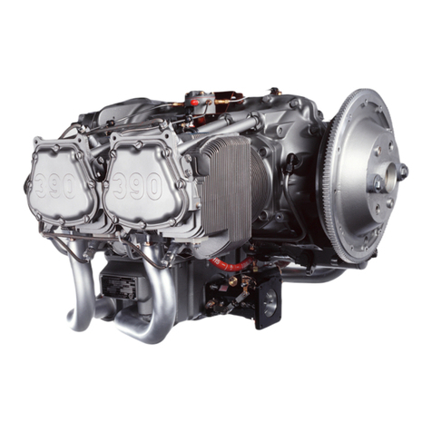
Sonex Aircraft Aerovee 2.1 Instruction Manual

AEROVEE 2.1
ASSEMBLY and INSTALLATION
ACV-R02 Rev Z. 01/14/2015 Applies to AeroVee s/n 0440 and up. Includes top-mounted oil cooler.
A Product Line of Sonex Aircraft LLC
Photo for illustration only and does not represent the specic contents of your kit.
$35.00

2
AeroVee 2.1 Rev Z. 01/14/2015
Sonex Aircraft LLC © 2014 All Rights Reserved
TABLE of CONTENTS
Contents
Your feedback is welcome and encouraged as we continue to
improve this manual. Please send comments to tech@aerocon-
versions.com. Comments will be reviewed and considered for
inclusion in future revisions of this manual.
Your success is important to us. If you have any questions
while assembling your engine do not hesitate to seek technical
support by emailing [email protected].
Trigger Shaft Installation ........................................... 34
Spark Plug Installation............................................... 35
Intake Manifold Installation ....................................... 36
Alternator Installation ................................................ 37
Firewall Preparation ................................................... 38
Voltage Regulator Installation ............................................................38
Secondary Ignition Coil Installation ..................................................38
Mounting the Engine.................................................. 39
Mount Bushings .................................................................................39
Lifting the Engine ..............................................................................39
Mount Pin Detail Drawing and Typical Installation ..........................40
Magnatron Ignition Wiring......................................... 41
Electronic Ignition Wiring.......................................... 43
Spark Plug Wires........................................................ 44
Electronic Ignition Timing ......................................... 45
Alternator / Regulator Wiring .................................... 47
Starter Installation / Wiring........................................ 48
Oil Breather Tube........................................................ 49
Oil Cooler Installation Options.................................. 50
Oil Cooler - Bottom Mount.................................................... 51
Oil Cooler - Top Mount ......................................................... 52
Oil Cooler Removal / Bypass ................................................ 55
Exhaust Installation.................................................... 56
Installing EGT Probes ............................................................ 60
Fuel Supply ................................................................. 57
Engine Cooling Bafes .............................................. 59
Engine Oil.................................................................... 60
Approved Oils - Break-in Period ........................................... 60
Approved Oils - Post Break-in ............................................... 60
Priming the Engine and Setting the Oil Level ....................... 60
Oil Changes During Break-in Period ..................................... 60
Start-up and Break In ................................................. 61
Maintenance................................................................ 62
Minimum Maintenance Interval ............................................ 62
When to Rebuild Your AeroVee ............................................. 62
Torque Values ......................................................................... 62
Troubleshooting ......................................................... 63
Electrical Schematics................................................. 65
APPENDIX A: Sonex Cowl Openings ....................... 66
Details the installation of an AeroVee on a Sonex, Waiex, or
Xenos airframe.
Revision Log............................................................... 69
Part Numbers and Packing Lists .............................. 70
Table of Contents ......................................................... 2
IMPORTANT! ................................................................. 4
AeroVee Engine Kit Documentation ...................................................4
AeroVee Serial Number .......................................................................4
Assembly / Service Resources ................................... 4
Other AeroConversion Resources ........................................................4
AeroConversions' Service Bulletins ....................................................4
Additional Resources ...........................................................................4
Specications ............................................................... 5
Weights and Dimensions ......................................................................5
Mount Dimensions ...............................................................................5
Prop Hub Bolt Pattern ..........................................................................5
General Specications .........................................................................6
Cylinder Identication, Engine Orientation, Firing Order ...................6
Operating Limitations ..........................................................................6
Before You Begin... .................................................... 7
Crankshaft Assembly................................................... 8
Cam Assembly............................................................ 10
Connecting Rod Assembly........................................ 11
Crank Case Preparation............................................. 12
Crank Case Assembly................................................ 16
Piston and Cylinder Assembly.................................. 20
Compression Ratio Chart ....................................................... 21
Cylinder Head Installation ......................................... 22
Rocker Shaft Installation ........................................... 23
Oil Screen Installation................................................ 25
Oil Pump Installation.................................................. 26
Oil Cooler Installation ............................................................ 26
Operation Without an Oil Cooler ........................................... 26
Oil Seal Installation .................................................... 27
Prop Drive Lug Installation........................................ 28
Valve Adjustment........................................................ 29
Block-off Plates and Plugs ........................................ 30
Flywheel Installation .................................................. 31
Flywheel Magnet Orientation Check ..................................... 32
Accessory Plate Installation...................................... 33

3
AeroVee 2.1 Rev Z. 01/14/2015
Sonex Aircraft LLC © 2014 All Rights Reserved
IMPORTANT!
© 2013 Sonex Aircraft LLC. All Rights Reserved. The information
disclosed herein is the property of the originator who reserves all pat-
ent, design, proprietary, manufacturing, use and sales rights thereto,
except for the rights expressly granted to others. This document shall
not be reproduced nor shall the information contained within be
used by or disclosed to others except as expressly authorized by the
originator.
511 Aviation Road Oshkosh, WI 54902
Phone (920) 231-8297 fax (920) 426-8333
[email protected] www.aeroconversions.com
Distributed Worldwide by: Sonex Aircraft, LLC.
www.sonexaircraft.com
Disclaimer and Limited Warranty
THE EXPERIMENTAL AEROVEE ENGINE KIT IS
SOLD “AS IS”. NO WARRANTY IS EXPRESSED OR
IMPLIED!
Sonex Aircraft LLC makes every effort to assure the supplied
components of the AeroVee Engine Kit meet high quality and
durability standards, and warrants to the original purchaser
that these components are free of defects in material and
workmanship for the period of one year from the date of pur-
chase. This warranty does not apply to damage due directly or
indirectly to improper assembly, misuse, abuse, negligence or
accidents, repairs or alteration out side our facilities, or lack of
maintenance. Due to the experimental nature of the AeroVee
Engine Kit, the end user is solely responsible for determining
suitability of application, assembly, installation and operation.
Sonex Aircraft LLC and its agents will in no event be liable
for death, injuries to person or property, or incidental, contin-
gent, special, or consequential damages arising from the use of
our product.
Sonex Aircraft LLC and its agents will not be responsible
for any incidental or consequential damage including direct
or indirect labor, repair, medical, or legal expense in any way
attributable to the use of any AeroConversions, Inc. product
or to the delay or inconvenience caused by the necessity of
replacing or repairing any such item.
Engine Monitoring Instrumentation
Sonex Aircraft LLC requires the use of a the following
cockpit-installed engine monitoring instruments in every
engine installation: oil pressure, oil temperature, cylinder
head temperature (1 minimum), and exhaust gas temperature
(1 minimum). Failure to properly monitor your engine may
result in severe engine damage which is not covered under this
limited warranty.
Not TSO'd for Certied Aircraft
AeroVee Engine Kit Documentation
This manual is your primary document for the assembly and
operation of your Experimental AeroVee Engine Kit. The in-
cluded assembly DVD is an additional aide, but when there is
a discrepancy between this manual and the DVD, the informa-
tion in this manual takes precedence.
The manuals provided with the AeroVee kit are important
documents and should be kept with your aircraft's documents.
Keep Your Packing Lists
The packing list provided with each AeroVee kit lists the
specic parts provided for that specic engine. Please refer-
ence your packing list for correct part numbers when ordering
maintenance and repair parts for your particular engine.
In addition to the packing list secured to the outside of the
engine kit boxes, a duplicate packing list has been attached to
the back of the physical manual supplied with that engine.
Copies of (most) packing lists are archived by Sonex Aircraft
and you may request an electronic (PDF) copy. To get a copy,
provide evidence you own the engine for which you are re-
questing the original packing list as well as the engine's serial
number.
Engine Serial Number
The engine's serial number is stamped on the rear of the acces-
sory plate, above the starter. It is also recorded on your pack-
ing list. Record your engine's serial number below.
Engine Serial Number
Stamped on aft side of Accessory Plate, above the starter

4
AeroVee 2.1 Rev Z. 01/14/2015
Sonex Aircraft LLC © 2014 All Rights Reserved
ASSEMBLY/SERVICE RESOURCES
AeroConversions Resources
AeroConversions continually improves and monitors its prod-
ucts. It is in your best interest to stay abreast of these improve-
ments and implement them as needed.
AeroConversions Website
AeroConversions, Inc. maintains a website which is continu-
ously updated. Perhaps the most important part of the website
for an AeroVee builder/operator is the Service Bulletin sec-
tion. You are encouraged to periodically check for Service
Bulletins which may affect the performance of your AeroVee
engine.
The AeroConversion website is aeroconversions.com
AeroVee Internet Discussion Group
AeroConversions operates an internet discussion group which
is open to all owners and enthusiast of the AeroVee Engine
Kit. Joining this list will get you in touch with other engine
owners and is an additional form of mass-communication
between AeroConversions, Inc. and its customers.
Information on joining this list is located on the
AeroConversions website at aeroconversions.com.
AeroConversions Tech Support
AeroVee owners can receive individual tech support by email
or phone. We encourage you to contact us via email rst, as
this allows us the opportunity to formulate a clear, concise
answer to your question.
The email address is [email protected]
AeroConversions' Service Bulletins
AeroConversions, Inc. is committed to providing quality
products. We do this through the constant improvement of
our AeroVee Engine Kit, and also by identifying parts or
procedures which we feel require the attention of the existing
AeroVee Engine Kit eet.
When we identify parts or procedures which we feel require
the attention of AeroVee owners, we issue a Service Bulletin.
Required Service Bulletins
A Required Service Bulletin, as the name implies, must be
complied with. It may be a part or a procedure which we feel
must be corrected for the continued use of your engine.
Upon compliance of the Required Service Bulletin, an entry
must be made in your engine log book.
Required Service Bulletins are posted on the AeroConversions
website, announced on the AeroVee Internet Discussion
Group, and mailed to the address of record of each AeroVee
Engine Kit owner. It is your responsibility to keep us informed
of any address or engine ownership changes, and to check the
AeroConversions website for Required Service Bulletins.
Optional Service Bulletins
An optional Service Bulletin is issue when we identify an area
which we feel will contribute signicantly to the reliability/
longevity of the AeroVee engine. Optional Service Bulletins
need not be complied with but we strongly encourage all
AeroVee owners to implement the suggested change/upgrade.
Upon compliance of the Optional Service Bulletin, an entry
must be made in your engine log book.
Optional Service Bulletins are posted on the AeroConversions
website and announced on the AeroVee Internet Discussion
Group. It is your responsibility to check the AeroConversions
website for Optional Service Bulletins.
Keep Your Packing Lists
The packing list provided with each AeroVee kit lists the
specic parts provided for that specic engine. Please refer-
ence your packing list for correct part numbers when ordering
maintenance and repair parts for your particular engine.
In addition to the packing list secured to the outside of the
engine kit boxes, a duplicate packing list has been attached to
the back of the physical manual supplied with that engine.
Copies of (most) packing lists are archived by Sonex Aircraft
and you may request an electronic (PDF) copy. To get a copy,
provide evidence you own the engine for which you are re-
questing the original packing list as well as the engine's serial
number.
Additional Resources
There are many books, magazines, and videos available for
the assembly, maintenance, and operation of "Type 1"-based
engines. We highly recommend "How to Rebuild Your
Volkswagen Air-Cooled Engine" by Tom Wilson (ISBN 978-
0-89586-225-9).

5
AeroVee 2.1 Rev Z. 01/14/2015
Sonex Aircraft LLC © 2014 All Rights Reserved
30.00"
20.0625"
21.875"
w/ optional
air cleaner
18.875"
24.25"
4.875"
Prop Hub Bolt Pattern
9/16" Dia. Drive Lug Hole - Typical 6 places
5" O.D.
Drive Lugs Centered on 4" Dia. Bolt Circle
Weights and Dimensions:
Weight (Less Oil and Exhaust):
with Standard Pistons and Barrels .........................160 lbs.
Length ..........................................................................24.25”
Width ................................................................................30”
Height ......................................................................20.0625”
SPECIFICATIONS
4.8" 4.8"
5.55"
5.55"
Mount Dimensions (Viewed from behind)
See Page 40 for Motor Mount Pin Detail

6
AeroVee 2.1 Rev Z. 01/14/2015
Sonex Aircraft LLC © 2014 All Rights Reserved
SPECIFICATIONS
General Specications (Subject to change without notice)
Power and Displacement:
HP @ 3400 RPM ..........................................................80 HP
Static RPM @ WOT (with correct propeller) ...... 3000 RPM
Bore ............................................................................. 92mm
Stroke .......................................................................... 82mm
Displacement .............................................................. 2180cc
Compression Ratios (Builder Adjustable):
7.0:1 For use with automotive gasoline with a posted
(R+M)/2 of 90 or greater conforming with ASTM D 4814.
8.0:1 For aviation gasoline 91/98 minimum grade con-
forming to ASTM D 910
Ignition System:
Firing Order ........................................................... See Photo
Spark Plugs ........................................ Autolite 4163 or equal
Spark Plug Gap:
Top Plugs ....................................................................018”
Bottom Plugs ..............................................................032”
Timing:
Primary Ignition (Magnatrons) ........... Fixed @ 28o BTDC
Secondary Ignition (Electronic) ......................... 28o BTDC
Ignition Module Gap (Primary Ignition) .............. .010-.014”
Cooling and Lubrication:
Primary Cooling .............................................................. Air
Secondary Cooling ........................................................... Oil
Oil Capacity .......................................................2.75 US Qts.
Oil Type ............ See "Engine Oil" section for approved oils.
Fuel System:
Throttle Body .................... AeroInjector, ACV-C07S, 32mm
Approved Fuels:
7.0:1 Compression: Automotive gasoline with a posted
(R+M)/2 of 90 or greater conforming with ASTM D 4814.
8.0:1 Compression: Aviation gasoline 91/98 minimum
grade conforming to ASTM D 910.
Electrical System:
Battery Required (minimum) ......................... 12v @ 20 amp
Starter ......................................................................... Geared
Alternator....................................................................20 amp
Propeller Drive:
Propeller Drive ....................................................Direct (1:1)
Prop Bolt Pattern .......... 6 holes, 9/16" dia., on 4" dia. center
Prop Drive Bushings ......................... 9/16" dia. x 7/16” long
Valve Setting:
Valve Setting (cold) .......................................... 006" to .008"
Operating Limitations (Subject to change without notice)
Idle RPM .........................................................700-900 RPM
Cruise RPM ............................................. 3200 +/- 200 RPM
Maximum RPM ...................................................4,000 RPM
Oil Temp. - Min. ..........................................................160o F
Oil Temp. - Max. ........................................................ 230o F
Oil Pressure - Min. ..................... 10 PSI (hot oil, idle RPM)
Oil Pressure - Max. ...................................................100 PSI
Oil Pressure@ Cruise ............................................ 40-50 PSI
CHT @ Cruise .....................................................350o-375o F
CHT @ Climb (5min.) ................................................ 420o F
CHT Max. .................................................................... 450o F
EGT Max. .................................................................. 1400o F
Cylinder Identication, Engine Orientation,
and Firing Order
Cylinder Identication
For assembly and maintenance, the AeroVee uses the cylinder
identication numbers shown below.
Engine Orientation
When referencing the location / orientation of items on the
engine, "Front", "Back", "Left", and "Right" are used as if the
engine is installed in a tractor conguration and viewed from
behind the engine, as shown below.
Firing Order
The AeroVee has a "wasted spark" ignition system which al-
lows the spark plugs to re on non-combustion strokes as well
as combustion strokes. The arrows in this diagram illustrate
the order of combustion.
1
2
3
4
Front
Back
Left Right
CYLINDER NUMBERING, FIRING ORDER,
and ENGINE ORIENTATION

7
AeroVee 2.1 Rev Z. 01/14/2015
Sonex Aircraft LLC © 2014 All Rights Reserved
BEFORE YOU BEGIN...
Protect Yourself
Always wear safety glasses
When using paint and chemicals, work in a well ventilated
room and wear appropriate protective gear (gloves, mask,
etc.).
The use of compressed air to clean parts is not recommended.
Compressed air can send debris ying at great speed and cause
serious injury.
Do not use ammable liquids near open ignition sources such
as water heaters, furnaces, electric motors, etc.
Read, Understand, and Follow
the Instructions
Read through each procedure before performing the individual
steps.
Make sure you have the appropriate tools, parts, and consum-
ables on hand. Some procedures cannot be interrupted while
you track down that forgotten tool.
Photo References in this Manual
Photos in this manual are included to illustrate specic steps
and may not accurately illustrate what an engine looks like
during an actual build-up. Do not add or remove parts based
on the photographs in this manual. The step-by-step instruc-
tions are your only guide for adding or removing parts during
engine assembly.
Work Cleanly
Parts must be thoroughly cleaned with Mineral Spirits and in
many cases, lubricated, before assembly. Remove rust-inhibit-
ing coatings from each part.
The engine case and cylinder heads must be carefully cleaned
and inspected to remove any metal chips which may remain
from the machining process.
Work Smartly
Parts should never be forced into position. If excess effort
seems to be needed to assemble parts, STOP and investigate
the problem.
NEVER apply concentrated heat (such as with a torch) to
assemble or disassemble parts. Excess heat will damage parts
and result in a potentially dangerous engine installation.
Part Numbers and Packing Lists
The packing list provided with each AeroVee kit lists the
specic parts provided for that specic engine. Please refer-
ence your packing list for correct part numbers when ordering
maintenance and repair parts for your particular engine.
In addition to the packing list secured to the outside of the
engine kit boxes, a duplicate packing list has been attached to
the back of the physical manual supplied with that engine.
Copies of (most) packing lists are archived by Sonex Aircraft
and you may request an electronic (PDF) copy. To get a copy,
provide evidence you own the engine for which you are re-
questing the original packing list as well as the engine's serial
number.
AeroConversions reserves the right to supply compatible,
alternative replacement parts for any part of the core engine or
conversion package. Such parts may appear different than the
part originally provided in the kit or depicted in the manual,
and may bear a different part number, but will be functionally
identical or superior to the original kit-supplied component.
A Successful, Reliable Engine Installation Begins Here.
The use of compressed air to clean parts is not recommended.
Compressed air can send debris ying at great speed and
cause serious injury, as well as drive the debris deeper into
crevasses.

8
AeroVee 2.1 Rev Z. 01/14/2015
Sonex Aircraft LLC © 2014 All Rights Reserved
CRANKSHAFT ASSEMBLY
Tools Required:
__ Oven Heated to 400 degrees F.
__ Heat-proof Gloves
__ White Lithium Grease
__ 1/2” Impact Wrench with 30MM Socket
__ Locktite #242
__ Block of Wood
__ Hammer or Mallet
__ Torque wrench (80 ft. lbs. capacity)
Parts Required:
__ Prop Hub, ACV-H01-16
__ Prop Hub Bushing and Washer, ACV-H01-17
__ Crankshaft, ACV-P01-98
__ Oil Slinger, ACV-P01-101
__ #1 and #2 Bearings from Main Bearing Set, ACV-P01-57
Note: Bearing #1 is the small cylindrical bearing, Bearing #2
is the large cylindrical bearing without anges.
__ Retaining Ring, ACV-P01-64
__ Forward Woodruff Key, ACV-P01-99
__ Aft Woodruff Key, ACV-P01-104
__ Crank Timing Gear, ACV-P01-62
__ Bolt, ACV-Z01-74
1
2
Preparation:
__ 1. Inspect the bore of the Crank Timing Gear for burrs. If
necessary, lightly polish it with ne emery cloth.
__ 2. Thoroughly clean all parts with Mineral Spirits.
__ 3. Remove the four (4) hex plugs from the crankshaft and
thoroughly clean the crankshaft with Mineral Spirits.
Re-install the hex plugs with Locktite #242.
__ 4. Test t the prop hub. The prop hub should NOT slide
onto the crankshaft.
__ 5. Place the cleaned crankshaft in a freezer at least 12
hours prior to assembly.
__ 6. Heat an oven to 450o F. Place the crank timing gear and
prop hub in the oven and heat for 60 minutes.
__7. Apply an even coat of white lithium grease to the inside
surface of bearing #1 and bearing #2 from the Main
Bearing Set.
Assembly Instructions:
__ 1. Install the Aft Woodruff
Key into the crank-
shaft. Make sure it is
fully seated.
__ 2. Slide bearing #2 (with
an even coat of white
lithium grease applied
to the inside surface)
onto the crankshaft
with the machined
dot (arrow in photo)
toward the crankshaft's
counter-weight.
IMPORTANT. Perform steps 3 through 10 near the oven.
Once the parts are removed from the oven, work quickly
but carefully to assemble the crankshaft. DO NOT
FORCE PARTS ONTO THE CRANKSHAFT.
If a part does not go into place on the crankshaft, STOP.
Do not force it on and do not try to remove it. Contact
Sonex Aircraft LLC before continuing.
Note: If you have the optional pre-assembled crank shaft (part
number ACV-H01-20), skip to Step 10.

9
AeroVee 2.1 Rev Z. 01/14/2015
Sonex Aircraft LLC © 2014 All Rights Reserved
CRANKSHAFT ASSEMBLY
__ 4. Install the Retaining
Ring in the groove in
the crank.
4
__ 5. Enlarge the oil supply
hole in bearing #1 by
updrilling it with a #30
drill bit. Remove any
burrs which may occur
while drilling.
7
6 & 7
__ 6. Slide bearing #1 (with
an even coat of white
lithium grease applied
to the inside surface)
onto the crankshaft
with the machined dot
(arrow in photo) to-
ward the retaining ring.
__9. Align the keyway of the Prop Hub with the forward
woodruff key installed in the crankshaft and tap the
prop hub into place using a mallet and block of wood.
The prop hub must be tight against the oil slinger.
__10. After the prop hub cools to room temperature, remove
the bolt (ACV-Z01-74), apply Locktite 242 to its
threads, and re-install. Torque the bolt to 80 ft.-lbs.
8
__ 3. Install the Timing Gear
with the two machined
dots (arrow in photo)
facing away from bear-
ing #2.
3
Immediately install
Prop Hub Bushing
and Washer and Bolt
(ACV-Z01-74). Use an
impact wrench to tight-
en the bolt and push the
prop hub against the oil
slinger.
7
__ 7. Slide the Oil Slinger
onto the crankshaft
with the curved
(concave) side of the
slinger facing the end
of the crankshaft.
__8. Install the Forward
Woodruff Key into the
crankshaft.

10
AeroVee 2.1 Rev Z. 01/14/2015
Sonex Aircraft LLC © 2014 All Rights Reserved
CAM ASSEMBLY
Tools Required:
__ Socket Wrench
__ 13mm Socket
__ Torque Wrench (20 ft.-lbs. capacity)
__ "Red" Locktite (High Strength Threadlocker)
Parts Required:
__ Cam Gear, ACV-P01-49
__ Cam Shaft (w/ hardware), ACV-P01-72
Assembly Instructions:
Note: The Assembly Lube provided with the cam gear will be
used to lubricate the valve lifters in a later operation. Do not
lubricate the cam shaft bolts as instructed on the assembly lube
package included with the cam shaft.
Note: Cam shafts are supplied with varying hardware, all of
which is acceptable. Use the hardware supplied with the cam
to attach the cam gear. This may include either:
Cam Bolts with integral lock washers.
Cam bolts and wavy spring washers.
Cam bolts and tab lock washers.
Note: While not common, slight interference between the cam
and the connecting rods does occasionally occur. One cause of
this interference is a raised edge around the numbers stamped
in the shaft of the cam. Lightly polishing these numbers will
remove the raised edge and eliminate a possible source of
interference.
A raised edge around the stamped numbers on the cam can
sometimes cause interference with the connecting rods.
__1. Align the machined dot
on the face of the Cam
Gear (arrow in photo)
with the slot in the
Cam Shaft. Apply Red
Locktite to the bolts
and install the bolts and
washers (if provided).
__2. Torque the bolts to 20
ft-lbs.
__3. If tabbed washers were
provided with your cam
shaft, bend the tabs
against the bolt heads
with a at-blade screw-
driver.
1
3

11
AeroVee 2.1 Rev Z. 01/14/2015
Sonex Aircraft LLC © 2014 All Rights Reserved
CONNECTING ROD ASSEMBLY
Tools Required:
__ White Lithium Grease
__ Socket Wrench and Socket Set
__ Moly Lube
__ "Red" Locktite (High Strength Threadlocker)
__ Torque Wrench (40 ft-lbs. capacity)
__ Feeler Gauge
Parts Required:
__ Connecting Rods, ACV-P06-33 or ACV-P01-33
__ Rod Bearing Set, ACV-P01-59
__ Crankshaft Assembly
Note: Both parts of each con-
necting rod are stamped with
a unique number, identifying
them as matched parts. The
connecting rods must be re-
assembled as matched parts,
with the numbers together as
shown in this photograph.
Assembly Instructions:
__1. Remove the fastener from each Connecting Rod and
carefully separate the two parts. Do not scratch or score
the machined surface of the connecting rods.
__2. Wipe the mating
surfaces of the connect-
ing rods and bearing
halves so they are free
of oil and dust. Install
the bearing halves by
aligning the tab on
each bearing half with
the notch in each con-
necting rod and press-
ing the bearing halves
into place.
2
__4. The connecting rods
are attached to the
crankshaft, as shown in
the photo below, with
the stamped numbers
facing up. Be sure
to re-assemble the
connecting rods as
matched parts.
4
__5. ACV-P06-33 Rods Only (with starred bolt and nut):
Apply Moly Lube to each rod bolt and install. Torque
each bolt as follows:
___rst to 8 ft.-lbs.
___then to 15 ft.-lbs.
___then 24 ft.-lbs.
___Then the nal torque of 38 ft.-lbs.
ACV-P01-33 Rods Only (with hex bolt): Apply "Red"
Locktite (or, if supplied with your rods, ARP Ultra-
Torque) to the threads of each rod bolt and install.
Torque each bolt in four steps:
___rst to 8 ft.-lbs.
___then to 15 ft.-lbs.
___then 24 ft.-lbs.
___Then the nal torque of 30 ft.-lbs.
__6. Check each connecting rod for freedom of movement
and .005" to .020" side clearance.
4
Note: The clearance between the rod bearings and rod journals
must be between .002" and .0025". When assembling new
parts, as provided in the AeroVee 2.1 kit, the proper clearance
is often assumed. When rebuilding an engine using remanufac-
tured parts, this clearance must be checked. Detailed instruc-
tions for checking this clearance are given in Tom Wilson's
book "How to Rebuild Your Volkswagen Air Cooled Engine".
__3. Apply an even coat of white lithium grease to the ex-
posed surfaces of each bearing half.
The connecting rods are installed on the crankshaft in the
orientation shown above with the stamped numbers on each
rod facing up.

12
AeroVee 2.1 Rev Z. 01/14/2015
Sonex Aircraft LLC © 2014 All Rights Reserved
Cylinder Head Stud Placement
= Short Cylinder Head Stud (7-3/8" - 7-1/2" long)
= Medium Cylinder Head Stud (8" - 8-1/4" long)
= Long Cylinder Head Stud (9-5/16" - 9-3/4" long)
S
L
M
M
L
S M
L
Note: This threaded insert is
recessed in the case.
S
M
L
M
CRANK CASE PREPARATION
Tools Required:
__ Flat Blade Screwdriver
__ Rubber Mallet
__ Fine File
__ White Lithium Grease
Parts Required:
__ Engine Case
__ 8mm Head Stud Kit, ACV-P01-86
__ Case kit, ACV-P02-12
__ Main Bearing Dowel Pins (Set of 5), ACV-P01-46
__ Valve Lifters, ACV-P01-48
__ Main Bearing Set (split bearings only), ACV-P01-57
__ Cam Bearings, ACV-P01-58
__ Gasket Set, ACV-P02-15
Preparation:
__ 1. Separate the case halves and thoroughly clean them
with mineral spirits. Remove all traces of metal chips
and dust from the case. Pay particular attention to
removing metal chips which still cling to the edge of
machined surfaces (see photo) and to casting slag on the
inside of the case which may dislodge after the engine
is in service.
Assembly Instructions:
__1. Install the head studs as shown in the photos below.
__2. If you are painting the case, now is the best time to do
so. Mask off all machined surfaces, mating surfaces,
and holes before painting.
Note: We have had good luck using "Barbecue Black"
spray paint on the case and piston barrels.
Remove
Clinging
Chips
Remove clinging chips and loose slag from the cases interior.

13
AeroVee 2.1 Rev Z. 01/14/2015
Sonex Aircraft LLC © 2014 All Rights Reserved
CRANK CASE PREPARATION
__2. Lay the case on it's side so the oil pressure relief ports
in the bottom of the case are accessible.
__3. Find the oil pressure
relief plungers (2),
springs (1 long, 1
short), metal gaskets
(2) and retaining plugs
(2) in the Case Kit.
Note: The remainder
of the case kit may be
discarded as it is not
needed on the AeroVee.
__4. Insert the grooved
plunger, lightly lubri-
cated with motor oil,
solid end rst into the
oil pressure relief port
in the bottom of the
case near the prop hub.
Note: The plungers
must move freely in
the passages. If they do
not, clean the plungers
with ne emery cloth
until they do.
__5. Insert the long spring
behind the grooved
plunger.
__6. Place a metal gasket
on a retaining plug and
screw the plug into the
relief port.
__7. Insert the non-grooved
plunger, lightly lubri-
cated with motor oil,
solid end rst into the
oil pressure relief port
in the bottom of the
case near the ywheel.
Oil Pressure Relief Ports
__8. Insert the short spring
behind the non-grooved
plunger.
__9. Place a metal gasket
on a retaining plug and
screw the plug into the
relief port.
2
3
4
5, 6, & 9
__11. Wipe clean the case journals and the back of each Cam
Bearing and install the bearings in the left half of the
case. The following photos show where each bearing is
installed.
The Stud Seals slide over the 6 large studs in the right case
half.
10
10
The cam bearings are installed in the left case half as shown
in these photos. The left photo is the rear (ywheel end) of the
case, the right photo is the front (prop hub end).
11
7
__10. Install the Main Bearing Stud Seals (Qty. 6) from the
Gasket Set (ACV-P02-15). The seals slide over the 6
large studs in the right case half.

14
AeroVee 2.1 Rev Z. 01/14/2015
Sonex Aircraft LLC © 2014 All Rights Reserved
CRANK CASE PREPARATION
__12. The anged cam bearing for the right case half must
have its alignment tab led off. File the tab off with a
ne le.
__13. Wipe clean the case journals and the back of each Cam
Bearing and install the bearings in the right half of the
case. The following photos show where each bearing is
installed.
File the tab (arrow) off the anged bearing with a ne le.
12
__14. Test t each Valve Lifter in a guide. The lifters must
slide freely in the guides. If a lifter sticks, clean the
guide with very ne emery cloth. After test-tting, liber-
ally lubricate each lifter with white lithium grease and
install them in their guides.
The cam bearings are installed in the right case half as shown
in these photos. The right photo is the rear (ywheel end) of
the case, the left photo is the front (prop hub end).
13
__15. Test t the Cam Shaft in each case half to make sure
there is clearance between the lobes of the camshaft and
each valve lifter. Interference between the cam shaft and
a lifter must be investigated.
14
Test t each valve lifter to assure smooth operation.
Test t the camshaft to conrm there is clearance between the
lobes of the camshaft and each lifter.
__16. Install four (4) Dowel Pins in the right case half. Make
sure they are fully inserted.
15
Dowel Pins
16

15
AeroVee 2.1 Rev Z. 01/14/2015
Sonex Aircraft LLC © 2014 All Rights Reserved
CRANK CASE PREPARATION
__17. Install one (1) Dowel Pin in the left case half. Make
sure it is fully inserted.
__18. Install one half of the Split Main Bearing (from Main
Bearing Set, ACV-P01-57) into the middle journal of
each case half, carefully aligning the recess in the bear-
ing with the dowel pin in the journal. A light tap may be
required to properly seat each bearing half.
__19. Apply an even coat of white lithium grease to all of the
cam bearings and main bearings.
Align the recess in the bearing half with the dowel pin in the
bearing journal and press the bearings in place.
Recess
Dowel Pin
18

16
AeroVee 2.1 Rev Z. 01/14/2015
Sonex Aircraft LLC © 2014 All Rights Reserved
CRANK CASE ASSEMBLY
Tools Required:
__ White Lithium Grease
__ "Red" Locktite (High Strength Threadlocker)
__ Torque Wrench (25 ft-lbs. capacity)
__ Torque Wrench (227 ft-lbs. capacity)
__ Rubber Mallet
__ Feeler Gauge Set
__ 13, 19 and 36mm Sockets
__ Permatex Aviation Form-A-Gasket #3 or Flange Sealant
__ Cam Assembly Lubricant
Parts Required:
__ Previously Completed Sub-Assemblies
__ Main Bearing Set, Bearing #4 (Flanged), ACV-P01-57
__ Flywheel Assembly, ACV-F01-02
__ Cam Plug, ACV-P01-35
__ Gland Nut, ACV-P01-42
__ End Shim Kit, ACV-P02-19
__ Gland Nut Washer, ACV-P01-44
__ ACV-Z01-75, Elastic Stop Nut, 12mm, Qty. 6
__ ACV-Z01-16 Bolts, Qty. 3
__ ACV-Z01-23 Elastic Stop Nuts, Qty. 15
__ ACV-Z01-26 Washers, Qty. 17
__ ACV-Z01-28 Washers, Qty. 6
__ Cam Screw Gaskets from Gasket Kit), Qty. 2, ACV-P02-15
Assembly Instructions:
__1. Apply a coat of white
lithium grease to the
inside of Main Bearing
#4 and slide it onto the
end of the crank shaft
assembly. Make sure
the dowel pin hole is
toward the end of the
crankshaft.
__2. Carefully set the crank
shaft assembly into
right case half. Make
sure dowel pin hole in
each bearing is aligned
with the dowel pins in
the case half, and the
crankshaft assembly is
fully seated in the case
half.
__3. IMPORTANT! Temporarily mate the case halves and
rotate the crankshaft. Listen and "feel" for a knock
which may indicate the case is interfering with the con-
necting rods. If interference is detected:
a. Disassemble the case halves and identify the loca-
tion of the interference.
b. Remove crank assembly.
c. Taking care not to get grinding dust on other parts,
use a remove case material to provide at least .045"
clearance. Dremel-style motor tools work well for
this operation.
d. Reinstall the crankshaft assembly and repeat step 3
until all interference is eliminated.
Dowel Pin Hole
1
2
__4. Apply a small amount
of cam assembly
lubricant to each valve
lifter.
4
__6. IMPORTANT! Make sure the main bearings of the
crankshaft are still fully seated on the dowel pins in the
case half.
__5. Align the single dot on the gear of the cam shaft as-
sembly with the two dots on the gear of the crankshaft
assembly and rotate the cam down into the into the
cam bearings in the right case half. After seating the
camshaft in the bearing, make sure the dots still align as
shown in photo 5a.
5b
5a

17
AeroVee 2.1 Rev Z. 01/14/2015
Sonex Aircraft LLC © 2014 All Rights Reserved
CRANK CASE ASSEMBLY
__7. Align the 8 holes in the center of the ywheel with
the dowel pins on the end of the crankshaft. The hole
pattern permits the ywheel to be installed in only one
position.
__8. The ywheel is a tight
t onto the crankshaft.
It must go on squarely.
If it binds, remove it
and lightly polish the
dowel pins with ne
emery cloth. Once
the ywheel has been
started by hand, com-
plete the installation
by tightening the gland
with an impact wrench.
__9. Push the crankshaft
towards the back
(ywheel end) of the
engine and, with a
feeler gauge, measure
the gap between the
ywheel and the rear
main bearing. Record
this measurement in the
"Shim Chart".
__10. Complete the shim
chart by subtract-
ing .006" from gap
recorded in step 9. This
is the total thickness of
shims you will use to
set the proper end play.
__11. Clean the end shims
with a mild solvent to
remove the preserva-
tive.
__12. Select any combination
of three to ve shims
which most closely
equals the "Shim
Thickness" determined
in step 10.
Shim Chart:
Complete this chart to
determine the total thick-
ness of shims required. See
steps 9 through 10.
= 0.______"
- .006 "
= 0.______"
Gap (see Step 9)
Subtract .006"
Shim Thickness
Continue with step 11.
__13. Check your shim selection by sliding the shims, to-
gether with a feeler gauge, between the ywheel and the
main bearing. You should have between .003" and .006"
of end play.
If necessary, adjust your shim selection to achieve the
required end play of .003" to .006"
Set the shims aside for later installation.
__14. Remove the gland nut and ywheel from the crank
shaft. It may be necessary to use a ywheel puller.
__15. Carefully align the
Cam Plug, with its
closed (at) end out,
and install it in the cam
plug bore at the y-
wheel end of the case.
Note: Most cases have
a smooth cam bore for
a “ribbed” plug. Some
cases have a groove
in the cam bore for a
cam plug with a raised
bead.
ACV-P01-34
ACV-P01-35
Metal plug with a single
ridge. Used in cases
with a "grooved" cam
bore.
Plastic plug with a
ribbed diameter. Used
with a "smooth" cam
bore.
CAM
CAM PLUG
FLYWHEEL

18
AeroVee 2.1 Rev Z. 01/14/2015
Sonex Aircraft LLC © 2014 All Rights Reserved
CRANK CASE ASSEMBLY
__18. Place one ACV-Z01-28 washer and one ACV-Z01-75
12mm elastic stop nut on each of the six large studs. Do
not tighten the nuts at this time.
Torquing order for the six 12mm nuts. See steps 19 and 21.
__19. In the order shown in the photo above, torque the 6
large nuts to 15 foot-pounds.
__20. Check for free movement of the crankshaft. If interfer-
ence is detected, identify the source of the interference
(most likely poorly seated main or cam bearings).
Note: If the connecting rods are not held near their nor-
mal operating position while checking for interference,
you may experience interference which does not exist
on an assembled engine.
__16. Apply Permatex Avia-
tion Form-A-Gasket #3
or Flange Sealant to the
mating surfaces of the
case halves. Apply ac-
cording to the product
manufacturer's instruc-
tions. Apply sparingly.
__17. Note: While assem-
bling the case halves,
the lifters in the left
half will want to slide
out. This can be mini-
mized by giving them
each a heavy coat of
white lithium grease.
Assemble the two case
halves by placing the
left half over the right
half. Gently tap the left
half with a rubber mal-
let to seat it against the
right half of the case.
__21. In the order shown in the photo, re-torque the 6 large
nuts to 25 foot-pounds. Do not exceed 25 foot-pounds.
__22. Check for free movement of the crankshaft, as described
in step 20.
17
16
35
2
4
1
6
18, 19, 21
__25. Install an ACV-Z01-26 washer and ACV-Z01-23 stop
nut on the remaining (10) studs on the perimeter of the
case. Lightly tighten each nut.
There are 10 studs protruding through the case which serve
to join to two case halves. Each must have a washer and nut
installed (inset photo).
__23. Apply Permatex Avia-
tion Form-A-Gasket #3
to two (2) ACV-Z01-26
washers and place them
over the cam shaft
studs the lower left side
of the engine.
__24. Install an ACV-Z01-23
stop nut on each cam
shaft stud and lightly
tighten.
The cam shaft studs (A).
23, 24
A
25

19
AeroVee 2.1 Rev Z. 01/14/2015
Sonex Aircraft LLC © 2014 All Rights Reserved
CRANK CASE ASSEMBLY
__26. Install and lightly
tighten an ACV-Z01-16
hex head cap screw,
two (2) ACV-Z01-26
washers, and an ACV-
Z01-23 stop nut in each
of the three through-
holes which serve to
join to two case halves.
Minimal thread en-
gagement is normal.
Nuts will be ush with
ends of screws.
25
__27. Torque the two cam nuts (from step 24) to 10 ft.-lbs.
__28. Torque the remaining case-assembly nuts (from steps 25
and 26) to 13 ft-lbs. There is no dened order for torqu-
ing these nuts.
__29. Check for free movement of the crankshaft, as described
in step 20.

20
AeroVee 2.1 Rev Z. 01/14/2015
Sonex Aircraft LLC © 2014 All Rights Reserved
Tools Required:
__ Needle-Nose Pliers
__ SAE 30 Motor Oil
__ 1” Utility Brush
__ Permatex Aviation Form-A-Gasket No. 3 Sealant
__ Rubber Mallet
__ Ring Compressor
__ Vise-Grips
__ Micrometer Caliper
Parts Required:
__ Crank Case Sub-Assembly
__ Big Bore Piston and Cylinder Kit, ACV-P02-14
__ Barrel Shims, .090, ACV-P01-39
__ Barrel Shims, .040, ACV-P01-40
__ Barrel Shims, .060 (2 sets), ACV-P01-41
__ Super Tin, ACV-P06-71
PISTON & CYLINDER ASSEMBLY
1
3
5
tween the top of the piston and the top of the cylinder).
If the piston is below the top of the cylinder you have a
positive (+) deck height. If the piston is higher than the
top of the cylinder, you have a negative (-) deck height.
Use your measured deck height to determine which
cylinder shims are required from the chart on page 21.
__6. Remove the cylinder and piston assembly from the case.
__7. Apply a light coat of motor oil to the outside of each
piston and the inner wall of each cylinder.
__8. Install the cylinder shims (as required, see chart on next
page) onto each cylinder. Align the shims so they match
the reliefs in the cylinder for the case studs.
__ 9. Apply Permatex Aviation Form-A-Gasket No. 3 Sealant
to the shims and base of cylinder.
Assembly Instructions:
IMPORTANT: Pistons and
pins have been matched to
within 5 grams. Keep each
piston and pin together as a
set.
__ 1. Remove a piston ring
from each piston and
slide it squarely inside
it's matched cylin-
der. Measure the gap
between the ends of
the ring - it should be
between 0.012"-0.022".
Re-install the ring on
the piston.
__2. Re-install the piston
into the cylinder using
a ring compressor.
__3. Slide one piston and
cylinder assembly into
place on the crank
case. Install the piston
pin and make sure the
cylinder is well seated.
__ 4. Bring the piston to Top
Dead Center.
__5. Measure the deck
height (distance be-
11
__10. Rotate the crank to
bring a connecting rod
to top dead center - this
eases installation of the
piston and cylinder.
__11. Note: The arrow on
each piston face points
to the ywheel end of
the engine.
Partially slide the
cylinder over the head
studs. Push the piston
out the bottom of the
cylinder just far enough
to attach the piston to
the connecting rod with
a piston pin, and secure
the pin in place with a
snap ring on each side
of the piston pin.
Note: The snap rings
were included in the
piston/cylinder box.
11
Table of contents
Popular Engine manuals by other brands

Dietz
Dietz FDR operating instructions

Zenoah
Zenoah G620PU owner's manual
DANA
DANA BREVINI E Series Installation and maintenance manual
Briggs & Stratton
Briggs & Stratton 90000 series Operator's manual
Briggs & Stratton
Briggs & Stratton 31N800 Series Illustrated parts list
Leroy-Somer
Leroy-Somer Varmeca LS 71 Installation and Maintenance
