Bomm STATIX DP User manual
MCH_HQ00
5
STATIX R DP
Crucibles: 350, 600 or 1000 cc
This instruction manual is an integral part of the machine supply
and should accompany it whenever it is moved.
The manual must be carefully kept for the duration of the
machine's life and must in all cases be available for at least 10
years, it must therefore be kept in a known location and made
available to all the personnel concerned.
Do not connect the machine or put it into operation until this
manual has been read.
Pict.1
1 Optical reader
8 Water pump socket
2 Crucible lock lever
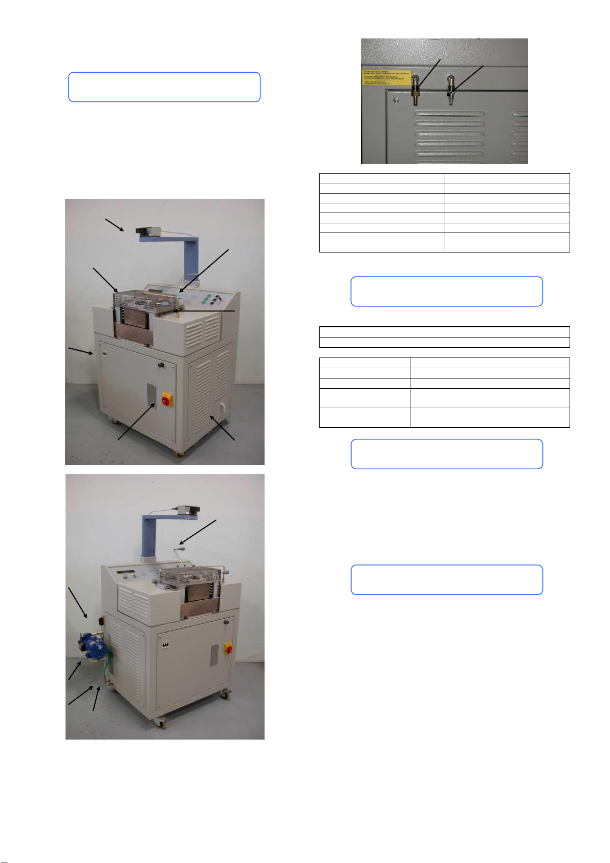
9 Water inlet pipe connection
3 Main switch
10 Water outlet pipe connection
4 Argon pipe
11 Water pump support
5 Casting area protection grid
12 Crucible tilting lever
6 Circuit breaker
13 Compressed air inlet
7 Power supply covering
panel
14 Argon gas inlet
STATIX F DP is avabile in the following versions:
380V 50-60Hz
Power
15kW
Depth
94 cm
Width
112 cm+ 20 cm for water pump
Height
117 cm + 34 cm of the optical reader
support
Controllable
temperature range:
800 1999°C
STATIX R DP is an electronic casting machine for alloys used in
jewellery technology field. Its aim is to melt by induction the alloy
placed in a special crucible. Once liquid the alloy can be poured
into the mold tilting the crucible by means of a special lever.
Any use other than the one described above is to be considered
improper and releases the manufacturer from all liability for
damage of any type and nullifies tha warranty rights on the
equipment itself.
The machine must be used by adult and suitably trained
personnel.
Given the weight of the machine, it must only ever be moved
with an appropriate trolley or on its wheels.
Never horizontally tilt the machine when moving or
transporting it. The machine must always rest on its feet.
If the machine needs to be moved after it has been installed,
always firstly empty the water from the tank.
Wear the dark glasses supplied. The light emitted from the
metal being cast could damage your sight.
Always use the relevant grips for removing the crucible.
Make sure that the electrical system has a ground fault
interrupter.
INTRODUCTION
SPECIFICHE TECNICHE
PURPOSE OF THE EQUIPMENT
PRECAUTIONS
TECHNICAL SPECIFICATIONS
1
3
6
7
2
5
12
4
14
13
10
9
11
8

MCH_HQ00
6
The machine is supplied in a wooden crate on a platform, proceed
ad follows to remove the packaging.
Cut the straps.
Remove the metal staples from the top of the crate and
remove the lid.
Remove the box of accessories and the electronic tube box
that are visible as soon as the crate is opened.
Remove the metal staples from the base of the crate.
Remove the side panels of the crate putting them upwards.
Remove the platform and stand the machine on the floor.
The machine must be placed in a dry and dust free premises, far
from boilers or flask furnaces, especially if they are gas-fired with
less than perfect draft.
.
Prepare a power lead consisting of three phase wires plus one for
ground connection. The cables must be of adequate cross-section
for the machine’s consumption requirement. Other user equipment
must not be connected on the machine line.
The machine must be connected to a socket suitable for the
power output and voltage as indicated on the rating and must be
grounded.
Power lead connection
1. Remove the terminal protection panel (7, pict.1) on the right
side of the machine.
2. Provide the ends of the cables with eyelets.
3. Loosen the nuts positioned on the line filters.
4. Insert the eyelets of the three phase cables on the screws
positioned above the line filters and the grounding connection
cable on the screw marked PE.
5. Secure the cables by means of the special nut.
Fitting the water pump
1. Unscrew the two bolts on the frame and use them to fix the
bracket supporting the water pump (11, pict. 1).
2. Pour water into the suction pipe while holding it upwards until
you see the water flow out of the outlet pipe, then place the
suction pipe into the tank and the outlet pipe into the water
inlet connector of the machine (9, pict. 1)
3. Connect a side of a pipe to the water outlet connector (10,
pict.1) and put the other side into the tank.
Fitting the tipping lever
Fit the tipping lever as shown in pict. 2.
Pict. 2
Fitting the optical reader
The optical reader is mounted on its support arm.
Fix the arm in the position illustrated in pict. 1 by means of the two
screws.
Connect the external socket that comes out of the back of the
optical reader.
Compressed air connection
Connect the machine to the external air compressor troughout the
suitable fitting (13, pict.1). For a correct driving of the heating coil
set the air pressure output at 6 bar minimum.
Pict. 3
1. Display
2. Encoder (by rotating it, it is possible to change the casting
parameter selected
3. Parameter selector (when pressed it changes the casting
parameter to be set: setpoint and casting power)
4. On button
5. Off button
6. Generator ON button
7. Generator OFF button
8. Casting ON button
9. Casting OFF button
10. Coil UP/DOWN lever (lever in up position = coil up, lever in
down position = coil down)
The display shown the following indications:
POWER SUPPLY
UNPACKING
POSITIONING
ACTIVATION
CONTROL PANEL
The machine must be earthed by law.
It must be installed by a qualified electrician capable of
checking that it is earthed.
The manufacturer declines all responsibility
for any damage or injury caused by failure
to comply with this requirement.
1
2
3
4
6
8
5
9
7
10

MCH_HQ00
7
P = XXX
PH = 0000
TEMP= 0850
T = 0900
P = 01250
ISW = 00.00
VTEST
TN = 040
TI = 060
OFF STOP
PHLIM
CR1
P
Casting power setted (min 260 –max 440)
T
Temperature to be reached
TEMP
Metal temperature measured
PH
Power output (min 260 –max 440)
P
Power output on the crucible ( kW)
ISW
Current measured on the power circuits
VTEST
This sign appears only when the machine si not heating. It
disappears when the casting is in ON.
TN
Power mosfet temperature (°C)
TI
Water cooling temperature (°C)
This symbol indicates that the machine is heating.
OFF
Generator status (OFF = not powered, ON= powered)
STOP
Heating status (STOP = not active, START = active)
PHLIM
It appears sometimes during the heating. Not relevant
CR1
It appears if the coil is down or if the casting protection
grid is open. When CR1 is present is not possible to start
casting
It is possible to set the parameters as below:
1. For changing the casting power press the parameters
selection button (3, pict.3) until the “>” symbol is visible near
to the P parameter:
P >XXX
PH = 0000
TEMP= 0850
T = 0900
P = 01250
ISW = 00.00
VTEST
TN = 040
TI = 060
OFF STOP
PHERR
CR1
or until the symbol is near to the T parameter to set the
casting temperature.
2. Rotate the encoder (2, pict.3) to change the parameter value.
Working parameters could be changed also when the casting is
ON: they are immediately executed.
1. Place the main switch (3, pict.1) at the position ON.
2. Turn on the automatic safety cut-out (6, pict.1).
3. Press the ON button (4, pict.3)
4. Set the working parameters as indicated in previous section.
5. Press the ON generator button (6, pict. 3): the OFF indication
on the display will disappear and it will be shown ON.
6. Put the crucible into its hole. Put the metal inside the crucible.
7. Lock the crucible with the crucible lock lever (2, pict.1)
8. Close the cating area protection grid (5, pict. 1)
9. Put the coil lever (10, pict.3) in up position: the casting coil will
rise up. If the coil doesn’t move, please check that the
machine is connected to the external compressed air supply.
10. Press the casting on button (8, pict.3) for start the casting.
Now the machine will start heating until the metal reach the
temperature setted. On the display the TEMP parameter will
shown the temperature of the metal.
When the metal is ready to be casted:
a. open the casting area protection grid (5, pict.1): casting
will be immediately stopped.
b. put the coil lever (10, pict.3) in down position.
c. Hold the crucible tipping lever (12, pict.1), pull with it the
crucible support, and after rotate the lever to pour the
crucible.
To stop in any moment the casting you can operate in one of the
following ways:
a. Open the casting area protection grid (5, pict.1)
b. Put the coil lever in down position (10, pict.3)
c. Press the casting OFF button (9, pict.3)
d. Press the generator OFF button (7, pict.3)
In all these situations the haeting will be stopped (STOP indication
on the display) and, except the (c) case, it will be also deactivated
the generator (OFF on display). To restart casting repeat the
wroking procedure from item (5).
NOTE: NEVER SWITCH OFF THE MACHINE (by pressing OFF
button (5, pict.3) or by puttin in OFF position the automatic safety
cutout (6, pict1) or the main swicth (3, pict.1)) WHEN THE COIL
IS UP AND WITH A WARM CRUCIBLE INSIDE. Risk to damage
the heating coil.
The reader is pre-set for all types of alloy. It is only necessary
to move a switch on the reader itself when the alloy has a very
high platinum content.When you wish to melt these types of
alloy slightly unscrew the four screws holding the cover. Move
the switch as shown in figure 6.
Always check that the mirror and the lens of the reader is
completely clean. The mirror is easy to get at. The lens is in a
horizontal position towards the instrument (fig. 6).
Fig. 6
Do not tamper with the two screws under the temperature
setter display.
Use very clean metal making sure that the recast heads are
sanded properly in such a way that all traces of coating that
could cause porosity are removed. Do not melt metals
covered in oil or grease etc.
Never leave the hot crucible in the heating coil of a machine
that is completely off and, generally, whenever water is not
circulating (lack of water, no power).
While melting inside the heating coil is under way, a high
frequency current flows through the metal.
Under no circumstances touch the coil or metal with hands or
metallic objects since you would risk getting a shock that while
not being dangerous is unpleasant.
Note:only use ceramic stirring rods to mix the metal while it is
melting.
WORKING PROCEDURE
WARNINGS
PARAMETERS SETTINGS
WARNINGS

MCH_HQ00
8
ALLOY
MELTING
TEMPERATURE
FLASK
CASTING
TEMPERATURE
SILVER FINE
961
427
SILVER (STERLING)
893
427
GOLD 10 K YELLOW
907
510
GOLD 14 K YELLOW
879
482
GOLD 18 K YELLOW
927
482
GOLD 10 K WHITE
1052
538
GOLD 14 K WHITE
996
510
GOLD 18 K WHITE
943
482
BERYLIUM COPPER
982
427
PLATINUM
1773
871
HERCULOY
927
482
BRON-WHITE
843
482
SILICON BRONZE
971
482
REYART
927
482
Note
1. Casting temperature should be approximately 40 - 70°C above
melting temperature.
2. Melting temperature will vary slightly according to the alloy
used.
3. Flask temperature will vary depending on the quantity of
casting.
4. Pure silver melts at 961°C.
5. Pure gold melts at 1063°C.
The device is guaranteed for 12 months.
The warranty is cancelled in cases of improper use, tampering or
the use of non-original spare parts.
The warranty is automatically cancelled in the event that crucibles
that are not of our production are used on the device.
Failure to return the Warranty Card, implies the immediate
cancellation of the same.
The warranty does not cover labour or transport charges that
are always and in all circumstances to be borne by the
purchaser.
WARRANTY
CASTING TEMPERATURE CHART
WARRANTY
This manual suits for next models
2
Popular Test Equipment manuals by other brands


Alcohawk
Alcohawk AT7000 Operation manual

R&S
R&S RTO6 Getting started

Agilent Technologies
Agilent Technologies 54622A user guide

Frye
Frye FONIX FA10 manual

The Diagnostic Box
The Diagnostic Box TDB760 operating manual

MAHA Maschinenbau Haldenwang
MAHA Maschinenbau Haldenwang MPP 2140 Original operating instructions

Schumacher Electric
Schumacher Electric PTI100 owner's manual

Tektronix
Tektronix SC 501 instruction manual

Rohde & Schwarz
Rohde & Schwarz RTM2032 user manual

MULTI MEASURING INSTRUMENTS CO.,LTD.
MULTI MEASURING INSTRUMENTS CO.,LTD. MIS-2D instruction manual

Hioki
Hioki 3554 instruction manual

Sealey
Sealey Auto Service Line VS2030 instructions