Sampson Equipment MX825-J User manual

MX825-JMulti-function process calibrator Users Manual
I
Thank you for purchasing the MX825-J Multi-function process calibrator. This manual describes the configuration,
operation and maintenance of the MX825-J Multi-function process calibrator. To ensure correct use, please read this
manual thoroughly and have a clear understanding of the calibrator before operation.
Notes
•This manual should be read by the end user.
•UK SAMPSON EQUIPMENT INTERNATIONAL LIMITED warrants goods of its manufactures being free of defective materials
and faulty workmanship. If warranted goods are returned to UK SAMPSON EQUIPMENT INTERNATIONAL LIMITED or its
representatives during the period of coverage of one year, UK SAMPSON EQUIPMENT INTERNATIONAL LIMITED will repair
or replace without charge any defective items. UK SAMPSON EQUIPMENT INTERNATIONAL LIMITED guarantees all the
goods with life maintenance.
•Specifications or other contents of this manual are subject to change without prior notice for improvement. When there is a
possibility that the foregoing change may result in serious accident or injury, UK SAMPSON EQUIPMENT INTERNATIONAL
LIMITED will give notice in advance.
•Every effort has been made in the preparation of this manual to ensure the accuracy of its contents. However, should you
have any questions or find any errors, please contact your nearest customer service.
•Do not modify this. UK SAMPSON EQUIPMENT INTERNATIONAL LIMITED assumes no liability for any loss or damage, direct
or indirect, caused by the user.
•Copying or reproducing all or any part of the contents of this manual without the permission of UK SAMPSON EQUIPMENT
INTERNATIONAL LIMITED.
MX825-J Multi-function process calibrator Users Manual
II
Symbol Definitions
Warning
This symbol indicates a hazardous situation, which, if not avoided, could result in death, serious injury or
property damage.
Caution
This symbol indicates a potentially hazardous situation, which, if not avoided, might result in damage to the
MX825-J Multi-function process calibrator or surroundings.

MX825-J Multi-function process calibrator Users Manual
III
Warning
•Do not apply more than the rated voltage, as marked on the MX825-J Multi-function process calibrator, between the jacks, or
between any jacks and earth ground. Maximum for all jacks is 30V, 24mA.
•Do not operate the MX825-J Multi-function process calibrator in the presence of flammable liquids or vapors, since operation
in such environments constitutes a safety hazard.
•Never disassemble, remodel, modify, or repair this MX825-J Multi-function process calibrator. Otherwise malfunction, electric
shock, or failure may result.
•Never use the MX825-J Multi-function process calibrator if it is found damaged or deformed when unpacked. Otherwise a fire,
malfunction, or failure may result.
•Disconnect the power and discharge all high voltage capacitors in the equipment under test before testing resistances.
•Inspect the test leads for damaged insulation or exposed metal. Check test lead continuity. Replace damaged test leads before
using the MX825-J Multi-function process calibrator.
•Do not use the MX825-J Multi-function process calibrator if it operates abnormally. Select the proper function for your
measurement. Connect the test leads to the flashing jacks.
•Charge the battery as soon as there is a low battery indication on the display.
•Do not use the MX825-J Multi-function process calibrator with any part of the case or cover removed.
•Do not measure a voltage source when the test leads are plugged into the current jacks.
MX825-J Multi-function process calibrator Users Manual
IV
Caution
•When you turn on the MX825-J Multi-function process calibrator, you had better measure known voltage to confirm it can be
operated normally.
•Make sure the battery door is closed before you operate the MX825-J Multi-function process calibrator.
•Remove test leads from the MX825-J Multi-function process calibrator before you open the battery door.
•When using the leads, keep your fingers away from the lead contacts. Keep your fingers behind finger guards on the leads.
•Dispose the MX825-J Multi-function process calibrator as an industrial waste.

MX825-J Multi-function process calibrator Users Manual
V
CONTENTS
1Introduction .................................................................................................................................................................. 1
2Standard Equipments................................................................................................................................................... 1
3Getting started.............................................................................................................................................................. 5
4MX825-J Multi-function process calibrator Summary............................................................................................... 7
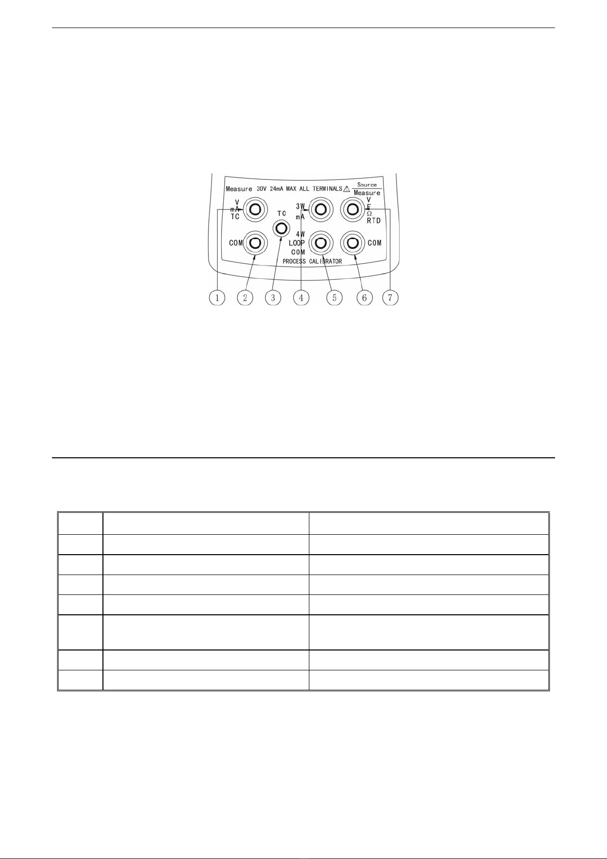
4.1 Jacks...................................................................................................................................................................... 7
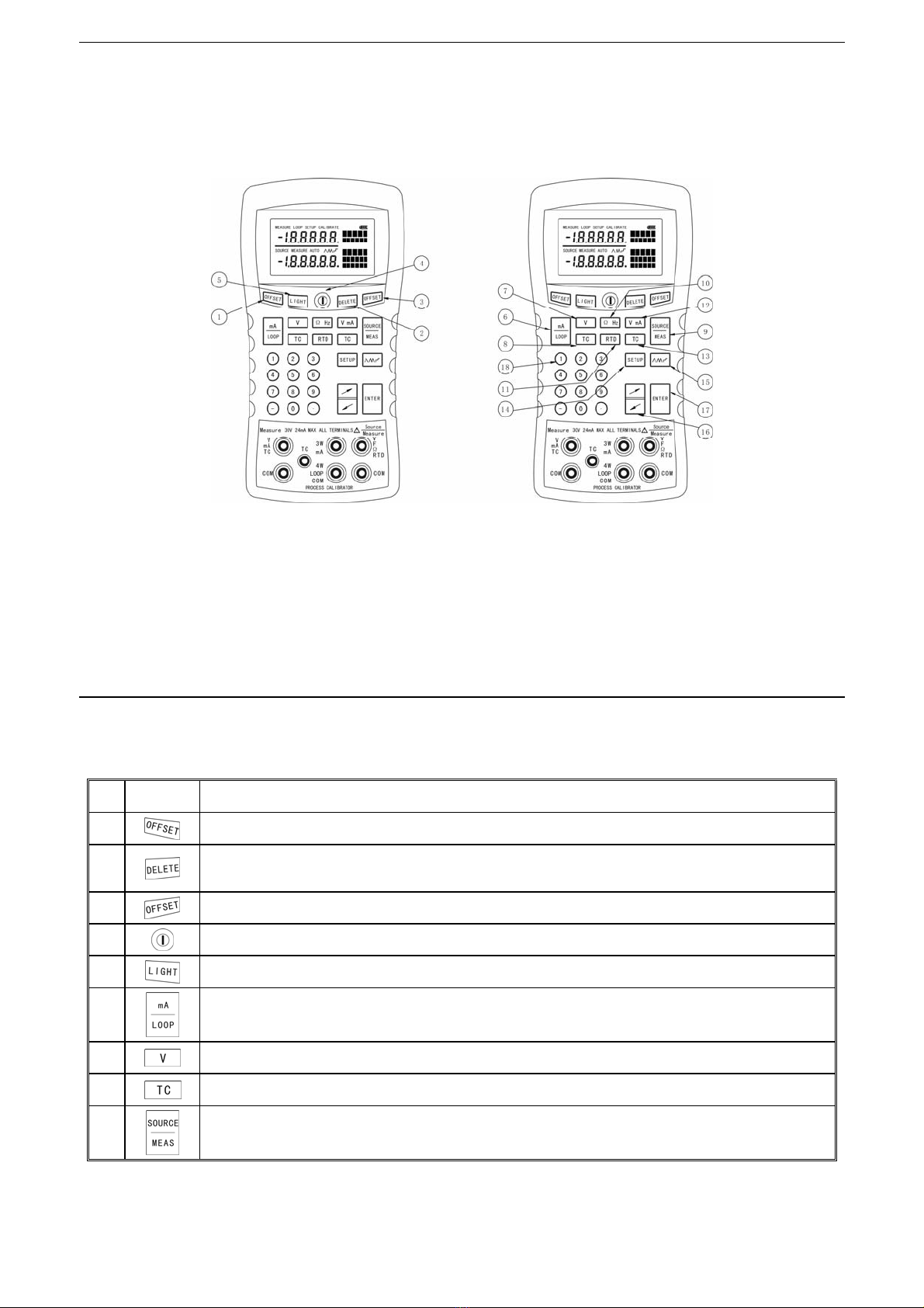
4.2 Keys ....................................................................................................................................................................... 9
4.3 Display ................................................................................................................................................................. 12
5Using Measure Mode ................................................................................................................................................. 13
5.1 Measuring Voltage (Upper Display)...................................................................................................................... 13
5.2 Measuring Current (Upper Display) ..................................................................................................................... 13
5.3 Measure current with loop power ......................................................................................................................... 13
5.4 Measuring Voltage (Lower Display)...................................................................................................................... 16
5.5 Measuring Resistance.......................................................................................................................................... 16
5.6 Measuring Frequency .......................................................................................................................................... 18
MX825-J Multi-function process calibrator Users Manual
VI
5.7 Counting pulse ..................................................................................................................................................... 18
5.8 Measuring Temperature with TC .......................................................................................................................... 20
5.9 Measuring Temperature with RTDs...................................................................................................................... 20
6Using Source Mode.................................................................................................................................................... 25
6.1 Sourcing Voltage.................................................................................................................................................. 25
6.2 Sourcing Current.................................................................................................................................................. 25
6.3 Sourcing Resistance ............................................................................................................................................ 27
6.4 Sourcing Frequency............................................................................................................................................. 27
6.5 Simulating Thermocouples................................................................................................................................... 29
6.6 Simulating RTD.................................................................................................................................................... 29
6.7 Ramping and Stepping the Output ....................................................................................................................... 31
6.8 Simulating Transmitter ......................................................................................................................................... 31
7Cold Junction ............................................................................................................................................................. 33
8Switching Temperature Unit ...................................................................................................................................... 33
9Calibration................................................................................................................................................................... 34
9.1 Equipments Required........................................................................................................................................... 34
9.2 Entry and Exit....................................................................................................................................................... 34
9.3 Calibration............................................................................................................................................................ 35

MX825-J Multi-function process calibrator Users Manual
VII
9.3.1 Calibrating Sourcing ................................................................................................................................................................35
9.3.2 Calibrating Measurement ........................................................................................................................................................36
9.3.3 Calibrating Cold Junction ........................................................................................................................................................36
10 Clear Function ............................................................................................................................................................ 38
10.1 Clear of Measuring Voltage.................................................................................................................................. 38
10.2 Clear of Sourcing Voltage .................................................................................................................................... 39
10.3 Clear of Measuring with TC.................................................................................................................................. 40
10.4 Clear of Resistance and RTD............................................................................................................................... 40
10.5 Clear of Sourcing TC............................................................................................................................................ 41
11 Calibrating a Transmitter ........................................................................................................................................... 41
12 Maintenance................................................................................................................................................................ 43
13 Specifications ............................................................................................................................................................. 44
14 Optional Parts............................................................................................................................................................. 50

MX825-JMulti-function process calibrator Users Manual
1
1 Introduction
MX825-J Multi-function process calibrator is a handheld, battery-powered instrument that measures and sources a variety of parameters.
It can be widely applied in industrial fields and laboratories. The summary functions of the Multi-function process MX825-J Multi-function
process calibrator are shown in Table2-1. In addition to these functions, the MX825-J Multi-function process calibrator has other
features as follows:
•A split-screen display. The upper display shows measure
parameters while the lower one shows measure or source
parameters;
•Counting pulse function;
•Calibration functions;
•Auto ramping and auto stepping;
•Manual and automatic cold junction compensating;
•Clear function;
•Temperature unit switching
•Auto flashing jacks;
•Backlight LCD;
•Battery gauge.
2 Standard Equipments
The items listed below and shown in Figure2-1 are included in your Counting pulse function. If the Counting pulse function is damaged or
something is missing, contact our service center immediately. To order the optional parts, see ‘14 Optional Parts’.
•Counting pulse function
•Counting pulse function Users Manual
•Alligator clips (one set)
•Test probes (one set)
•Test leads (one set)
•Battery charge
MX825-J Multi-function process calibrator Users Manual
2
•4 AA rechargeable batteries

MX825-J Multi-function process calibrator Users Manual
3
Table2-1 Summary of Source and Measure Functions
Measure Source/Measure
Function
Measure Measure Source
V DC (0~30)V (0~20)V (0~10)V
mV DC (0~100)mV (0~100)mV (0~100)mV
mA DC (0~24)mA — (0~24)mA
Current loop (0~24)mA — —
Transmitter signal — — (0~24)mA
Counting pulse — 0~99999 —
Frequency — (1~10k)Hz (1~5k)Hz
Resistance — (0~3200)Ω(15~3200)Ω
TC(Thermocouple) J, K, T, E, R, S, B, N
RTD
(Resistance-
Temperature
Detector)
— Cu50
Pt100(385)
MX825-J Multi-function process calibrator Users Manual
4
Figure2-1 Standard Equipment

MX825-J Multi-function process calibrator Users Manual
5
3 Getting started
When you first unpack the MX825-J Multi-function process calibrator, you will need to charge the battery. After reinstalling the battery,
please perform the test of sourcing and measuring V DC as follows, it will make be easier to understand the instructions in the rest of the
manual.
(1) Press to turn on the MX825-J Multi-function process
calibrator.
(2) Clearing offset of measuring V DC in the upper display and
sourcing V DC in the lower display according to ‘10 Clear
Function’.
(3) Press to select DC voltage.
(4) Press for Source mode. Press to select
sourcing V DC.
(5) According to the flashing jacks,connect the MX825-J
Multi-function process calibrator’s voltage output to its
voltage input as Figure3-1 shows.
(6) Enter the desired output value by press numeric keys on the
keypad and press to begin sourcing V DC.
(7) The MX825-J Multi-function process calibrator is
simultaneously sourcing V DC and measuring V DC. You
should see the measurement readings in the upper display,
and the active source value in the lower display.
MX825-J Multi-function process calibrator Users Manual
6
Figure3-1 Source/Measure V DC

MX825-J Multi-function process calibrator Users Manual
7
4 MX825-J Multi-function process calibrator Summary
4.1 Jacks
Figure4-1 shows the MX825-J Multi-function process calibrator Source/Measure jacks and Table4-1 explains their use.
Auto flash jacks willl guide you to the correct connecting. For example, after you select to measure voltage in lower display, ⑥and ⑦in
Figure4-1 will flash, and then you can put the test leads into the jacks correctly.
Figure4-1 Source /Measure Jacks
MX825-J Multi-function process calibrator Users Manual
8
Table4-1 Measure/Source Jacks
No. Function Description
①② Jacks for measuring voltage, current and TC. The measurement reading is shown in the upper display.
③Jack for measuring TC cold junction. Automatic cold junction.
④⑤ Jacks for sourcing current. The source reading is shown in the lower display.
⑤⑥ Jacks for simulating transmitter. The source reading is shown in the lower display.
⑥⑦ Jacks for measuring or sourcing voltage, frequency,
resistance, counting pulse, TC and 2-wire RTD.
The measurement or source reading is shown in the lower
display.
④⑥⑦ Jacks for measuring 3-wire resistance and RTD. The measurement reading is shown in the lower display.
④⑤⑥⑦ Jacks for measuring 4-wire resistance and RTD. The measurement reading is shown in the lower display.

MX825-J Multi-function process calibrator Users Manual
9
4.2 Keys
Figure4-2 shows the MX825-J Multi-function process calibrator keys and Table4-2 explains their functions.
Figure4-2 Keys
MX825-J Multi-function process calibrator Users Manual
10
Table4-2 Keys Functions
No. Key Description
①Clears offset of Measure mode in the upper display.
②
Deletes the last digit of input data;
Clears the counting pulse.
③Clears offset of Measure and Source modes in the lower display.
④Turns the power on and off.
⑤Turns the backlight on and off.
⑥
Selects the mA or mA Loop measurement function in the upper display.
⑦Selects voltage measurement function in the upper display.
⑧Selects TC measurement function in the upper display.
⑨
Switches between Measure and Source modes in the lower display.

MX825-J Multi-function process calibrator Users Manual
11
Description
No. Key
Measure mode Source mode
⑩Selects resistance or frequency measurement functions. Selects resistance or frequency sourcing functions.
Selects RTD measurement function. Selects RTD sourcing function.
Selects voltage or mA measurement functions. Selects voltage sourcing function.
Selects TC measurement function. Selects TC sourcing function.
Switches temperature unit, enters and exits Setup mode, sets cold junction temperature, and so on.
Cycles through:
Slow repeating 0%~100%~0% ramp;
Fast repeating 0%~100%~0% ramp;
Repeating 0%~25%~50%~75%~100%~0% step.
Increases the source value,least significant digit +1;
Decreases the source value,least significant digit -1.
Terminates a numeric entry, when setting a source value;
Begin/Stop counting pulse;
Confirm your choice in a list.
Numeric
keypad Used whenever a numeric entry is required.
MX825-J Multi-function process calibrator Users Manual
12
4.3 Display
Figure4-3 shows the elements of a typical display.
Figure4-3 Elements of a Typical Display

MX825-J Multi-function process calibrator Users Manual
13
5 Using Measure Mode
5.1 Measuring Voltage (Upper Display)
To measure the voltage, proceed as follows.
(1) Press until the upper display shows “mV” or “V”.
(2) Connect the test leads as shown in Figure5-1.
You should see the measurement readings in the upper display.
5.2 Measuring Current (Upper Display)
To measure the current, proceed as follows:
(1) Press until the upper display shows “MEASURE”.
(2) Connect the test leads as shown in Figure5-2.
You should see the measurement readings in the upper display.
5.3 Measure current with loop power
(1) Press until the upper display shows “MEASURE
LOOP”.
(2) Connect the test leads to the transmitter current loop jacks
as shown in Figure5-3.
(3) The MX825-J Multi-function process calibrator supplies an
internal 24V loop power.
You should see the measurement readings in the upper display.
CAUTION: Never short two test leads in “MEASURE
LOOP” mode.
MX825-J Multi-function process calibrator Users Manual
14
Figure5-1 Measuring Voltage (Upper Display)
Figure5-2 Measuring Current (Upper Display)

MX825-J Multi-function process calibrator Users Manual
15
Figure5-3 Connections for Supplying Loop Power
MX825-J Multi-function process calibrator Users Manual
16
5.4 Measuring Voltage (Lower Display)
To measure the voltage, proceed as follows:
(1) Press until the lower display shows “MEASURE”.
(2) Press to select DC voltage until the display shows
“V” or “mV”.
(3) Connect the test leads as shown in Figure5-4.
You should see the measurement readings in the lower display.
5.5 Measuring Resistance
To measure the resistance, proceed as follows:
(1) Press until the lower display shows “MEASURE”.
(2) Press to select resistance until the display shows
“Ω”.
(3) Connect the test leads as shown in Figure5-5.
You should see the measurement readings in the lower display.
CAUTION: Clear of resistance before measuring,
according to ‘10.4 Clear of Resistance and RTD’.

MX825-J Multi-function process calibrator Users Manual
17
Figure5-4 Measuring Voltage (Lower Display)
Figure5-5 Measuring Resistance
MX825-J Multi-function process calibrator Users Manual
18
5.6 Measuring Frequency
The function of Measuring Frequency is only applicable to
MX825-J Multi-function process calibrator. To measure the
frequency, proceed as follows:
(1) Press until the lower display shows “MEASURE”.
(2) Press to select frequency until the display shows
“Hz”.
(3) Connect the test leads as shown in Figure5-6.
You should see the measurement readings in the lower display.
5.7 Counting pulse
The function of counting pulse is only applicable to MX825-J
Multi-function process calibrator. To use this function, proceed as
follows:
(1) Press until the lower display shows “MEASURE”.
(2) Press to select counting pulse until the display
shows “COUNT”.
(3) Connect the test leads as shown in Figure5-7.
(4) Press to start counting, and press again to
stop counting. Press to clear the result.
Pulse counting is shown in the lower display, the range is 0~99999.
The display shows “-OL” when input overflows. The time is
displayed by seconds at the bottom right corner.

MX825-J Multi-function process calibrator Users Manual
19
Figure5-6 Measuring Frequency
Figure5-7 Connection of Counting Pulse
Figure 12 Connection of Counting Pulse
MX825-J Multi-function process calibrator Users Manual
20
5.8 Measuring Temperature with TC
The MX825-J Multi-function process calibrator supports eight
types of standard TC. Table5-1 summarizes the ranges and
characteristics of the supported TC. Change the unit of
temperature according to ‘8 Switching Temperature Unit‘.
To measure temperature using a TC, proceed as follows:
(1) Press until the lower display shows “MEASURE".
(2) Press to select the desired thermocouple type.
(3) Connect the leads as shown in Figure5-8.
You should see the measurement readings in the lower display.
5.9 Measuring Temperature with RTDs
The MX825-J Multi-function process calibrator accepts RTD
types shown in Table5-2. RTDs are characterized by their
resistance at 0°C, which is called the “ice point” or R0. The most
common R0is 100Ω. The MX825-J Multi-function process
calibrator accepts RTD measurement input in 2-, 3-, or 4-wire
connections, with the 3-wire connection the most common.
Change the unit of temperature according to ‘8 Switching
Temperature Unit’.
To measure temperature using an RTD input, proceed as follows:
(1) Press until the lower display shows “MEASURE”.
(2) Press to select the desired RTD type.
(3) Press to select a 2-, 3-, or 4-wire mode. Connect the
test leads as shown in Figure5-9.
CAUTION: Please pay attention to the cold junction
temperature, and if necessary, press to set the cold
junction temperature manually.

MX825-J Multi-function process calibrator Users Manual
21
CAUTION: Clear of RTD before measuring, according to
‘10.4 Clear of Resistance and RTD’.
MX825-J Multi-function process calibrator Users Manual
22
Table5-1 Thermocouple Types Accepted
Type Specified Range
J (-200~1200)°C
K (-200~1370)°C
T (-200~400)°C
E (-100~950)°C
R (-20~1750)°C
S (-20~1750)°C
B (600~1800)°C
N (-200~1300)°C
Table5-2 RTD Types Accepted
Type Ice Point(R0)αRange
Cu50 50Ω0.00428Ω/°C (-50~150)°C
Pt100(385) 100Ω0.00385Ω/°C (-200~800)°C
Pt100(3916) 100Ω0.003916Ω/°C (-200~510)°C
Pt200(385) 200Ω0.00385Ω/°C (-200~630)°C
Pt500(385) 500Ω0.00385Ω/°C (-200~630)°C
Pt1000(385) 1000Ω0.00385Ω/°C (-200~630)°C

MX825-J Multi-function process calibrator Users Manual
23
Figure5-8 Measuring Temperature with a TC
MX825-J Multi-function process calibrator Users Manual
24
Figure5-9 Measuring Temperature with an RTD

MX825-J Multi-function process calibrator Users Manual
25
6 Using Source Mode
In Source mode, the MX825-J Multi-function process calibrator generates calibrated signals for testing and calibrating process
instruments, supplies voltages and resistances, and simulates the electrical output of RTD and TC temperature sensors. These signals are
sourced and shown in the lower display.
6.1 Sourcing Voltage
To select a voltage sourcing function, proceed as follows:
(1) Press until the lower display shows “SOURCE”.
(2) Press to select voltage until the display shows “V” or
“mV”.
(3) Connect the test leads as shown in Figure6-1.
(4) Enter the desired output value by pressing numeric keypads
and press .
6.2 Sourcing Current
The function of Sourcing Current is only applicable to MX825-J
Multi-function process calibrator. To select a current sourcing
function, proceed as follows:
(1) Press until the lower display shows “SOURCE”.
(2) Press to select current until the display shows “mA”.
(3) Connect the test leads as shown in Figure6-2.
(4) Enter the desired output value by pressing numeric keypads
and press .
MX825-J Multi-function process calibrator Users Manual
26
Figure6-1 Voltage Sourcing Connections
Figure6-2 Current Sourcing Connections

MX825-J Multi-function process calibrator Users Manual
27
6.3 Sourcing Resistance
To select a resistance sourcing function, proceed as follows:
(1) Press until the lower display shows “SOURCE”.
(2) Press to select resistance until the display shows
“Ω”.
(3) Connect the test leads as shown in Figure6-3.
(4) Enter the desired output value by pressing numeric keypads
and press .
6.4 Sourcing Frequency
The function of Sourcing Frequency is only applicable to MX825-J
Multi-function process calibrator. To select a frequency sourcing
function, proceed as follows:
(1) Press until the lower display shows “SOURCE”.
(2) Press to select frequency until the display shows
“Hz”.
(3) Connect the test leads as shown in Figure6-4.
(4) Enter the desired output value by pressing numeric keypads
and press .
Amplitude of the output frequency is displayed at the bottom right
corner. You can press to adjust the amplitude. The step of
amplitude is 0.5V, and the range is (0-8)V.
CAUTION: Clear of resistance before sourcing according to
‘10.4 Clear of Resistance and RTD’.
MX825-J Multi-function process calibrator Users Manual
28
Figure6-3 Resistance Sourcing Connections
Figure6-4 Frequency Sourcing Connections

MX825-J Multi-function process calibrator Users Manual
29
6.5 Simulating Thermocouples
To select Simulating Thermocouples function, proceed as follows:
(1) Press until the lower display shows “SOURCE”.
(2) Press to select TC type. Continue pressing it to
select the desired TC type.
(3) Connect the test leads as shown in Figure6-5.
(4) Enter the desired output value by pressing the numeric
keypads and press .
6.6 Simulating RTD
To select Simulate an RTD function, proceed as follows:
(1) Press until the lower display shows “SOURCE”.
(2) Press to select RTD display. Continue pressing it to
select the desired RTD type.
(3) Connect the test leads as shown in Figure6-6.
(4) Enter the desired output value by pressing the numeric
keypads and press .
CAUTION: MX825-J Multi-function process calibrator can
only simulate 2-wire connection.
CAUTION: Clear of RTD before simulating according to
‘10.4 Clear of Resistance and RTD’.
CAUTION: Please pay attention to the current cold junction
temperature, and if necessary, press to adjust the cold
junction temperature manually.
MX825-J Multi-function process calibrator Users Manual
30
Figure6-5 Connections for Simulating a Thermocouple
Figure6-6 Connections for Simulating an RTD

MX825-J Multi-function process calibrator Users Manual
31
6.7 Ramping and Stepping the Output
Two ways are available for adjusting the value of source function.
•Stepping the output manually with or numeric
keypads;
•Auto ramping the output.
Auto ramping can be applied in all sourcing functions, which allow
you to source a varying output from the MX825-J Multi-function
process calibrator continuously.
When you press , the MX825-J Multi-function process
calibrator produces a continuously repeating 0% ~ 100% ~ 0%
ramp in your choice of three ramp waveforms:
0%~100%~0% 40 seconds smooth ramp;
0%~100%~0% 10 seconds smooth ramp;
0%-25%-50%-75%-100%-0%, stair-step ramp in 25%
steps, pausing 25 seconds at each step.
Press any key to exit ramping.
6.8 Simulating Transmitter
The function of Simulating Transmitter is only applicable to
MX825-J Multi-function process calibrator.
Proceed as follows to simulate transmitter:
(1) Press until the display shows “SOURCE”.
(2) Press to select simulating transmitter until the
display shows “LOOP mA”. The MX825-J Multi-function
process calibrator produces a variable resistance to
regulate current to the specified value.
(3) Connect an external loop power supply as shown in
Figure6-7.
(4) Enter the desired output value by pressing numeric keypads
and press .
MX825-J Multi-function process calibrator Users Manual
32
Figure6-7 Connections for Simulating a Transmitter
Table of contents
Popular Test Equipment manuals by other brands

Seaward
Seaward PowerTest 200 user manual

Ulta-Lit Tree
Ulta-Lit Tree LIGHTkeeper PRO quick start guide

Agilent Technologies
Agilent Technologies InfiniiVision 7000B Series Product fact sheet

Keysight
Keysight N109228CA OIF CEI 3.1 Getting started

McPower
McPower PC-101 Reference manual

GOLDSUN
GOLDSUN TCT-910 user manual

Clearaudio
Clearaudio double matrix professional SONIC user manual

norbar
norbar 43228 Operator's manual

Megger
Megger MFT1700 series quick start guide

Bartington
Bartington SCU1 Operation manual

Rohde & Schwarz
Rohde & Schwarz RTP Series Getting started

Coopers of Stortford
Coopers of Stortford F946 Instructions for use