Bonnet SR 1200SG700 User manual

FORM050D1/3 n° 6BE648286NI-0606
REFRIGERATED BASES
TOQUE BLANCHE
GRANDE CARTE
INSTALLATION MANUAL
MANUFACTURERS SPECIFICATION
BONNET GRANDE CUISINE
Rue des Frères Lumière - Z.I. Mitry Compans
77292 MITRY MORY cedex
Tél. 01 60 93 70 00 - Fax. 01 60 93 70 43
9

IMPORTANT RECOMMENDATIONS
∗The installation should be entrusted to approved contractors and
comply with all current regulations.
∗Before locating the unit ensure that the air circulation and volume
are sufficient to allow normal cooling of the condenser and
compressor.
∗Avoid installing the cabinet near major sources of heat or in direct
sunlight.
∗Note that too high an ambient operating temperature can reduce
performance
∗When connecting electrically earth continuity must be maintained
between the unit and the supply socket.
∗The supply cable that is fitted is a specific part and should only be
replaced with an original part. Ensure that the plug is easily accessible
as a means of electrical isolation.
∗Protection against electrical overload or faults is the responsibility of
the installer. Ensure that a circuit breaker or fuses are fitted in the
supply circuit (See data plate).
∗All operations on the electrical or refrigeration circuits, including
cleaning should only be undertaken with the unit DISCONNECTED
(unplugged)
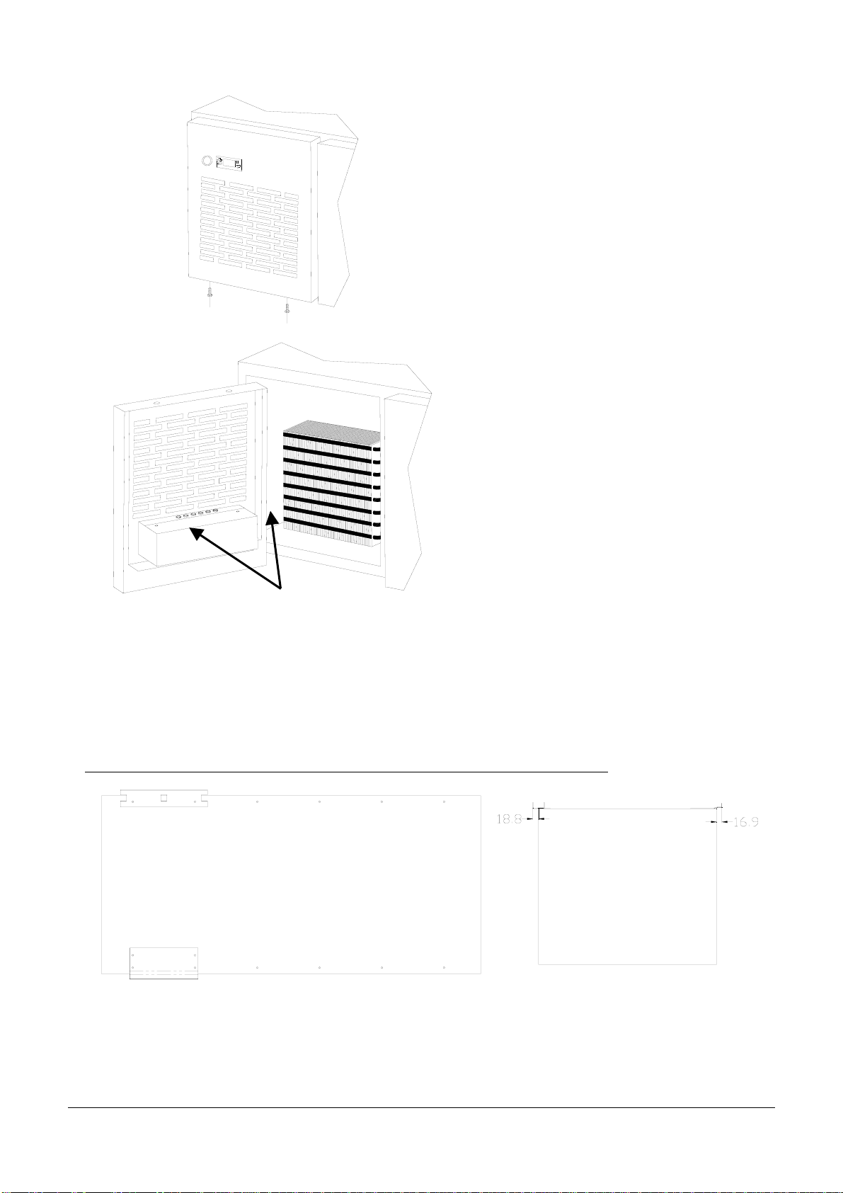
∗The air cooled compressor condenser must be cleaned regularly
(Every 3 to 6 months).
∗The unit should not be sprayed or splashed with water:
. Do not use a jet wash on the exterior or technical parts of the
unit.
. The equipment must not be installed in the fresh air or exposed
to the elements.
∗Correct functioning depends on the factory fitted safety systems being
respected. No responsibility can be accepted for malfunctions that
result from modifications undertaken on our equipment.
∗The manufacturer can not be held responsible so the equipment be
used for anything other than the purpose it was designed for.
ALL SPECIFICATIONS AND CHARACTERISTICS IN THIS
MANUAL MAY BE SUBJECT TO CHANGE WITHOUT NOTICE

n° 6BE648286NI-0606 – Page 1
CONTENTS
REFRIGERATED BASES
TOQUE BLANCHE
GRANDE CARTE
1. Technical Characteristics 2
2. Identification plate .....................................….….. 4
3. Installation: General features …….…………………………………..…. 5
4. Installation: Connections .……….……… …………………………...….. 9
BONNET GRANDE CUISINE
Rue des Frères Lumière - Z.I. Mitry Compans
77292 MITRY MORY cedex
Tél. 01 60 93 70 00 - Fax. 01 60 93 70 43

n° 6BE648286NI-0606 – Page 2
1. TECHNICAL CHARACTERISTICS
Toque Blanche, Refrigerated bases
1200 without compressor: S100C11 1600 with compressor: S100C12
MODEL SR 1200SG700 SR 1600GR700
DIMENSIONS (mm)
Base width A1200 1600
Leg centres B980 1380
Width C120 205
Width D720 1120
Height x Depth 630 x 620
PACKAGING (mm)
Height 900 900
Width 1300 1700
Depth 800 800
WEIGHT (KG) 80 120
BASE COMPRISES
Refrigeration unit compartment - 1
GN 21/1 door 2 2
200 mm door - 1
ELECTRICITY
Power (kW) Single ph. 230V a.c. 0.45 0.45
Intensity (A) Single ph. 230V a.c. 4 4
DRAIN 20mm Ø PVC drain outlet
REFRIGERATION POWER (at –15/+55°)
Power (Watts) - 321
REQUIRED REFRIGERATION POWER (at –15/+55°)
Power (Watts) 321 -
ELECTRICAL CONNECTION
Inlet at 200 mm from floor
Appliance fitted with a contactor
Grande carte, Refrigerated bases

n° 6BE648286NI-0606 – Page 3
1200 with compressor: S100C13 1600 without compressor: S100C14 2000 with compressor: S100C15
MODEL SR 1200GR900 SR 1600SG900 SR 2000GR900
DIMENSIONS (mm)
Base width A1200 1600 2000
Leg centres B980 1380 1780
Width C235 120 200
Width D315 915 1315
Height x Depth 630 x 740
PACKAGING (mm)
Height 900 900 900
Width 1300 1700 2100
Depth 800 800 800
WEIGHT (KG) 110 130 180
BASE COMPRISES
Refrigeration unit compartment 1 - 1
GN 1/1 door - - -
GN 2/1 door 1 2 2
Cupboard - - 1
ELECTRICITY
Power (kW) Single ph. 230V a.c. 0.45 0.45 0.45
Intensity (A) Single ph. 230V a.c. 4 4 4
DRAIN 20mm Ø PVC drain outlet
REFRIGERATION POWER (at –15/+55°)
Power (Watts) 321 - 321
REQUIRED REFRIGERATION POWER (at –15/+55°)
Power (Watts) - 321 -
ELECTRICAL CONNECTION
Inlet at 200 mm from floor
Appliance fitted with a contactor

n° 6BE648286NI-0606 – Page 4
2. IDENTIFICATION PLATE
The identification plate is fixed onto the inside of the compressor compartment, on the left hand
side (see Diagrams below).
In any correspondence about your equipment, please quote:
- The model number (Type.)
- The serial number (N° SERIE).
- The date (Date).
Identification plate
DateType
Désignation
N° SERIE
Tension VHz
Puissance WClasse
Refrigérant g
Eclairage WDégivrage W
WP Max. b Réévap. d'eau
A
g
A
Dégivrage
Réévap. d'eau W
W
Classe
W
Hz
Date
Refrigérant
P Max.
Eclairage
b
N° SERIE
Puissance
Tension
Désignation
Type
W
V
g
A
Dégivrage
Réévap. d'eau W
W
Classe
W
Hz
Date
Refrigérant
P Max.
Eclairage
b
N° SERIE
Puissance
Tension
Désignation
Type
W
V
g
A
Dégivrage
Réévap. d'eau W
W
Classe
W
Hz
Date
Refrigérant
P Max.
Eclairage
b
N° SERIE
Puissance
Tension
Désignation
Type
W
V
Emplacement de la plaque signalétique

n° 6BE648286NI-0606 – Page 5
3. INSTALLATION
TYPE AND POSITION OF CONNECTIONS
See "Technical data" at the beginning of these instructions.
3.1 GENERAL REQUIREMENTS
zThe installation or repair of this appliance should be carried out according to current
regulations by a qualified engineer.
zThe appliance must be installed in compliance with the appropriate standards, in an
adequately ventilated area.
zThese appliances should ideally be against a wall. The latter must be of non-combustible
materials or, if not, should be covered with an appropriate material, good insulator, non-
combustible.
zAvoid locating in direct sunlight or adjacent to sources of heat.
zThe manufacturer certifies that the packing conforms to directive 94/62/CE of 20.12.94 and
requests that the final recipient respects the directive with regard to recycling or reuse of the
packaging materials.
3.2 HANDLING
The appliance should only be handled with specialised lifting equipment.
Should the appliance need to be transported, it must be done on its original pallet and must not
be stacked under any circumstance.
If the appliance is to be moved without a pallet, it should be carried and not dragged.
3.3 UNPACKING
Before installation, remove the strapping from the appliance. The individual parts are not bolted
down. Remove plastic covers from the stainless steel parts before heating the appliance.
Level using the adjustable feet (20mm spanner) .

n° 6BE648286NI-0606 – Page 6
3.4 ACCESS TO COMPONENTS WITHIN THE HOUSING
- Switch off.
- Undo the two compressor door fixing
screws and open it.
- Turn the door round to gain access to the
cover fixing screws.
- Undo the two cover fixing screws and
removing it.
For re-assembly, reverse the above order of operation.
2.5 ASSEMBLY OF ITEMS ON A REFRIGERATED BASE
- Position the front and rear fixing brackets in the indicated positions using two 4.8mm Ø rivets .
One bracket for a 400mm module and two for an 800 or 1200 unit. (400 centres for an 800 and 800 for a 1200).
TOQUE BLANCHE SERIES COOKING TOPS (for units not incorporating drainage)
Screw
Front of the refrigerated base
Front of the
refrigerated
base

n° 6BE648286NI-0606 – Page 7
TOQUE BLANCHE SERIES COOKING TOPS (Including items with drainage)
GRANDE CARTE SERIES COOKING TOPS (for units not incorporating drainage)
GRANDE CARTE SERIES COOKING TOPS (Including items with drainage)
Front of the refrigerated base
Front of the
refrigerated
base
Front of the refrigerated base
Front of the
refrigerated
base
Front of the refrigerated base
Front of the
refrigerated
base

n° 6BE648286NI-0606 – Page 8
- Place the units on the base as follows
Toque Blanche Grande Carte
A 710 900
B 620 740
C 70 140.5
- Fix appliances to the base on the rear brackets usingthree screws HM5 X 10 + 5mmø washers 5.
- Connect the units together at the rear flue vents.
- And at the front behind the facia.
Fixing holes

n° 6BE648286NI-0606 – Page 9
4. INSTALLATION : CONNECTIONS
4.1 ELECTRICAL CONNECTION
Connect the appliance before it is finally located.
- Follow the procedure to access items within the housing.
- Undo the two screws holding the access panel on the back of the unit.
- Pass the supply cable through the cable gland and out through the rear access panel.
- Tighten the cable gland
- Refit the rear access panel.
- Connect the wiring to the unit.
- Refit the cover and the compressor compartment door.
IMPORTANT: Only electrical cable type HO 7 RNF with cross-section 3 x 1.5 mm2 should be used.
Provide a suitable isolating device (with contact separation of at least 3mm) in accordance with
current regulations.
The installation comply with current applicable national legislation (for France, standard NF
15.100)
The appliance must be connected to the earth. The various electrical appliances must also be
connected with an equipotential contact (every metal part must have the same voltage) to the
equipotential terminal located on the cooking tops.
The manufacturer cannot be held responsible in the event that these instructions are not
respected.

n° 6BE648286NI-0606 – Page 10
4.2 DRAIN CONNECTION
•PVC drain connection 15/21mm Ø plumbed to waste
50 mm
minimum
IMPORTANT: The drain connection should comply with current guidelines especially concerning
cross contamination, connection with an air gap is recommended, a direct connection
may not conform to local regulations.
The drain should be trapped to avoid odours.
Recommended solution:
50 mm
100 mm Ø trapped tundish
(trapped below slab or gully)
This manual suits for next models
4