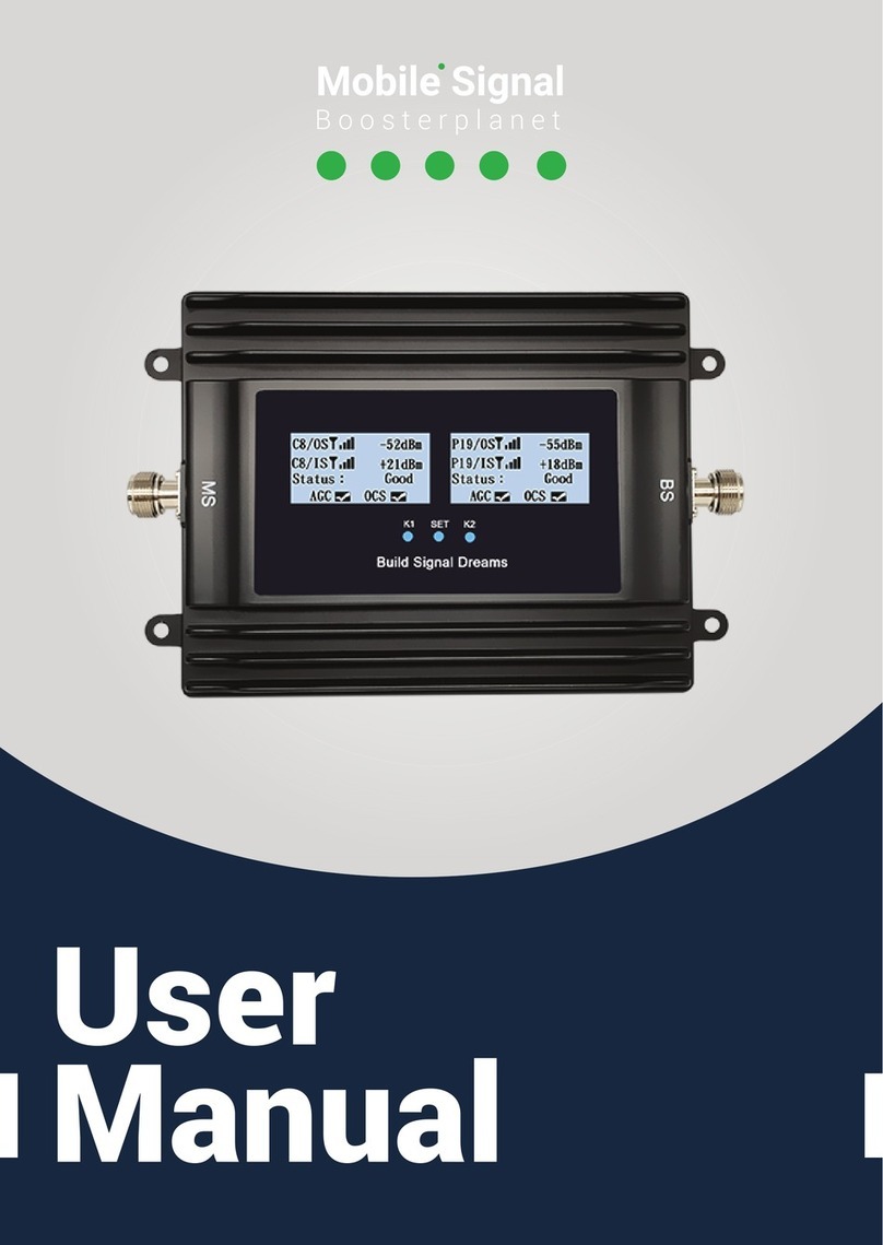
Boosterplanet C23F-5B User manual

PLEASE KEEP APPROPRIATELY AND CAREFULLY READ THIS USER MANUAL BEFORE INSTALLATION
C23F-5B Mobile Signal Booster
User Manual

2
Content
PACKAGE CONTENTS..........................................................................................................3
PRODUCT DESCRIPTION.................................................................................................... 3
PRODUCT FEATURES.......................................................................................................... 3
CONNECTOR DESCRIPTION...............................................................................................4
LED INDICATOR DESCRIPTION.........................................................................................5
ATT OPERATION.................................................................................................................... 5
TECHNICAL SPECIFICATION..............................................................................................6
INSTALLATION GUIDES....................................................................................................... 6
Installation Requirements........................................................................................................................6
Installation Tools........................................................................................................................................7
Installation Steps....................................................................................................................................... 7
Starting......................................................................................................................................................... 9
MAINTENANCE....................................................................................................................... 9
Operation and Maintenance.................................................................................................................... 9
Notes............................................................................................................................................................. 9
The power supply voltage of the
booster should meet the standards of
security requirements
Ensure of grounding, waterproof and
lightning protection when installing
the booster
Booster should be installed and
operated by the professionals
Do not open the booster, maintain or
replace the components
Keep booster away from heat source
and do not install it in a narrow space

3
Package Contents
C23F-5B signal booster, 1pc Power adapter, 1pc Screws, 1bag Mounting frame, 1bag
Outdoor antenna, 1pc Indoor antenna, 1pc 32 ft coax cable, 1pc 16 feet coax cable, 1pc
Product Description
Carried with features like low consumption, light weight, high gain, low output power and easy
installation, C23F-5B signal booster provides a rapid solution to optimize the weak signal of houses,
offices, hotels, elevators, underground parking lots and other small weak signal areas.
On the condition that to assure the normal communication, C23F-5B uses the smallest Rx and
Tx power to achieve the link balance among base station, mobile phone and boosters, guaranteed
that the least Rx and Tx power from the products, the least harm to environmental pollution and
human body's radiation.
C23F-5B series has ALC function, which offers the product reliability and ensure stable signal
output technically. In addition, ALC alarm function to let users know the signal quality and working
status of the device by observing the indicator's color.
Product Features
Support amplifying 2G, 3G, 4G networks of all carriers in USA & Canada
With 70dB gain, able to cover areas of up to 8000 square feet
Low power consumption, low interference
Quality metal construction, strong and durable
Separate gain attenuation for each band
Separate power and alarm LED indicator lights for each band, to clearly see the working
status of each band
ALC(Auto Level Control) function enables the device to automatically limit the output power
and ensure stable signal coverage

C23F-5B Mobile Signal Booster
4
I
G
Connector Description
A:Connect to outdoor antenna(N-Female)
B:Connect to indoor antenna(N-Female)
C:DC 12V power port
D:Grounding screw
E:PCS attenuation & alarm indicator
F:AWS attenuation & alarm indicator
G:CDMA attenuation & alarm indicator
H:LTE13 attenuation & alarm indicator
I:LTE12 attenuation & alarm indicator
C
A
F
D
E
B
H

5
LED Indicator Description
The indicator lights will indicate the situations as following:
POWER
Device powered on and indicator light on
Alarm
Orange--Downlink power Active 5~10dB/
Red--Downlink power Active 15~20dB
ATT Operation
If the Alarm indicator is RED, it means the signal is too strong and ALC is working. At this time,
attenuation should be adjusted to remove the alarm. First attenuate the DOWNLINK gain until the
Alarm indicator turn to Orange, and then attenuate the same value of UPLINK.
Attenuation Value
Operation Description
Downlink 1dB
Key ”1” turn to upside, other keys keep downside
Downlink 2dB
Key ”2” turn to upside, other keys keep downside
Downlink 3dB
Keys ”1” and ”2” turn to upside, other keys keep downside
Downlink 4dB
Key ”3” turn to upside, other keys keep downside
Downlink 5dB
Keys ”1” and ”3” turn to upside, other keys keep downside
Downlink 6dB
Keys ”2” and ”3” turn to upside, other keys keep downside
..............
The rest can be done in the same manner
Downlink 31dB
Keys 1、2、3、4、5 all turn to upside
Uplink 1dB
Key “6” turn to upside, other keys keep downside
Uplink 2dB
Key “7” turn to upside, other keys keep downside
Uplink 3dB
Key “6” and “7” turn to upside, other keys keep downside
Uplink 4dB
Key “8” turn to upside, other keys keep downside
Uplink 5dB
Keys “6” and “8” turn to upside, other keys keep downside
Uplink 6dB
Keys “7” and “8” turn to upside, other keys keep downside
..............
The rest can be done in the same manner
Uplink 31dB
Keys 6、7、8、9、10 all turn to upside

C23F-5B Mobile Signal Booster
6
Technical Specification
Items
Uplink
Downlink
Frequency
Range
LTE12
698 ~ 716 MHz
728 ~ 746 MHz
LTE13
776 ~ 787 MHz
746 ~ 757 MHz
CDMA
824 ~ 849 MHz
869 ~ 894 MHz
AWS
1710 ~ 1755 MHz
2110 ~ 2155 MHz
PCS
1850 ~ 1910 MHz
1930 ~ 1990 MHz
Output Power
17 ± 3 dBm
23 ± 3 dBm
Gain
65 ± 3dB
70 ± 3 dB
Ripple
≤8-10 dB
≤10 dB
Max. Input Power Without Damage
-40 dBm
-40 dBm
Intermodulation Products(CW)
≤-36 dBm
≤-40 dBc
Spurious
Emission
9KHz~1GHz
≤-36 dBm
≤-36 dBm
1GHz~12.75GHz
≤-30 dBm
≤-30 dBm
ALC Active 20dB
∣△∣≤2 dB
∣△∣≤2 dB
Alarm
ALC not Active
—
Green
ALC Active 5~10dB
—
Orange
ALC Active 15~20dB
—
Red
Self-oscillation
—
Red(device will turn off PA if ALC
is red and auto restart at 30s. If
ALC light remains red for times,
device will shut off permanently
until manually power up again)
Time Delay
≤0.5μs
Power Supply
DC:12 V
Power Consumption
<50 W
RF Connector
N-Female
Environment Conditions
IP40
Humidity
< 90%
Operating Temperature
-10℃~ +55℃
Installation Guides
Installation Requirements
1) With Stable and independent power supply.
2) The booster should be installed in the place without corrosive gas, smog and leaky liquid.
3) The booster should be installed on the wall that is ventilated, waterproof, lightning-proof and
without sunshine.
4) The height of installation site should be safe and easy for cabling, maintaining and dissipating
heat.

7
Installation Tools
No.
Items
Q’ty
Remarks
1
Percussion drill
1
Drill holes on wall, self-provided
2
Wrench
1
Reinforce the interface connection, self-provided
3
Expand plug, screws
4
Fix the device on the wall, included in the package
4
Mobile phone for testing
1
Test installation effectiveness, self-provided
5
Multimeter
1
Test voltage and wiring connection, self-provided
6
Screwdriver
1
Tighten or fasten the device, self-provided
7
Waterproof tape
A few
Prevent liquid from leaking into the feeder interface,
self-provided
Installation Steps
1) Find a site with the strongest signal for the outdoor antenna with your mobile phone by the way
below. And temporary install the outdoor antenna.The direction of the outdoor antenna should be
towards to nearest base station.
iPhone: Dial *3001#12345#*, then press call. Select “Serving Cell Measurement” to see the RSRP
or RSSI.
Android: Setting→ About Phone → Status or Network → Signal Strength or Network Type and
Strength (options depends on different phone models)
2) The installation site of the indoor antenna should be in the central of the weak signal zones that
you want to boost the signal. The distance between outdoor and indoor antennas should be 20
feet vertical or 50 feet horizontal.
3) Find a suitable site for the booster, according to the installation requirements and dimension of
the booster.
4) Drill 4 holes with the percussion drill according to the shell holes. Sizes are 7mm. Put the
expansion pipes(size: 8mm) into the 4 drilled holes.

C23F-5B Mobile Signal Booster
8
5) Align the fixing holes of the booster with corresponding holes on the wall, and drive 4 M6*40
screws into the expand plugs with screwdriver and fasten the booster firmly.
6) Connect coaxial cable from outdoor antenna to end of the booster labeled INPUT or BTS. The
length should be less than 65 feet. And connect coaxial cable from indoor antenna to end of
booster labeled OUTPUT or MS.
Better wrap the waterproof tape around the connection part of the outdoor antenna and
outdoor cable, in case of oxidization or corrosion.
7) Power up the booster and test if the signal is boosted or not. If the booster works well,
permanently install the outdoor and indoor antennas.

9
Starting
1)Firstly make sure all installation steps are finished, and power supply and grounding meet
the requirement. Then connect the booster to the power source. The indicator is on and green,
means that the booster is in normal working state.
2)Observe the indicator and adjust accordingly:
A. Power indicator:Light off--power supply disconnected; Green--power supply connected
B. Alarm indicator:After device powered on, adjust the ATT, the direction or height of the outdoor
antenna, until the indicator is green or orange.
3)If the indicator light is abnormal and cannot be normal working after adjustments, please
contact the supplier.
Maintenance
Operation and Maintenance
Power supply
Please make sure the voltage and frequency of AC power is in conformity with that of the booster.
Component replacement
Please do not maintain or replace the components by yourself, in case you may get an electric
shock. Only authorized personnel can maintain or replace the components.
Waterproof and moisture-proof
Please don’t turn on the equipment in a humid environment.
Notes
Power-off is recommended in the following situations:
Power supply is abnormal.
Liquid flows into the device.
Working conditions are abnormal such as overheating, strange smell or foreign matters
Performance is decreased
Too close to the fire
Table of contents
Other Boosterplanet Extender manuals
Popular Extender manuals by other brands

Luxul
Luxul PW100-24-FC2 Quick install guide

TP-Link
TP-Link AV500 Quick installation guide
J-Tech Digital
J-Tech Digital JTD-2994 user manual
Analog Devices
Analog Devices icron EL5353 quick start guide

zBoost
zBoost Xtreme Reach ZB560SL user manual
Honeywell
Honeywell Silent Knight EVS-CE4 Product installation document
