Booth EXL95H User manual

1
Product Manual
EXL95H/96H
Chiller/Cooler Carbonator
3B7961-OR
2
Contents
Section
Page
Section
Page
Introduction & Specification
2-3
Fault Finding
16-17
Model Numbering, Installation &
Commissioning
4-6
Replacement Parts
18-21
Wiring Schematics & Water
Circuits
7 -15
Removal, transportation
and Disposal
22
Introduction
The EXL95H & EXL96H units are med/high capacity chillers incorporating soda recirculation which
include an option of a cold carbonator incorporating soda recirculation. It is designed in a modular fashion
to cover a range of control options, with a single mechanical thermostat, or a choice of two digital
thermostats which are specified at time of order. They also have the capacity to incorporate up to 6 syrup
cooling coils.
The wiring schematics included in the following pages reflect this modularity:
Safety
The EXL95H/96H models use a R290 (Care 40, Propane) refrigerant. Below are some safety points
which the end user must adopt to mitigate the risk of unsafe conditions arising.
Service must only be carried out by a suitably qualified refrigeration engineer.
The unit must be isolated from the electricity supply before removal of the covers.
Do not damage the refrigeration circuit.
Ventilation openings must be clear of obstructions.
There must be a gap of at least 100mm between the appliance and a wall or other restriction.
Where electrical components are replaced, the new component must be of the same type.
Operate the unit within (ambient) operating temperatures; 10⁰C to 32⁰C.
Introduction and Specification
3
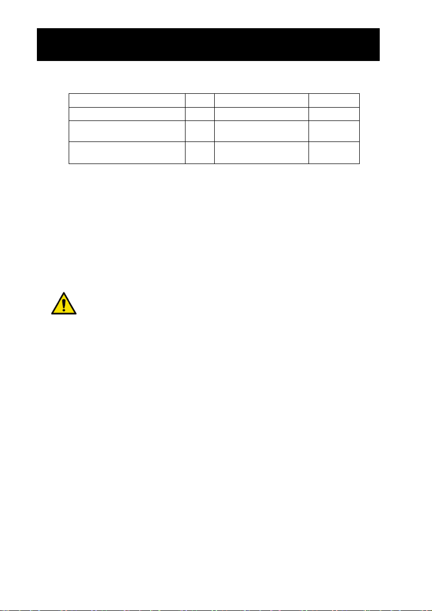
Specification
Dimensions
780mm(W)
Compressor
Cubigel
455mm(D) (EXL95H)
NPY12LAb (EXL95H)
512mm(D) (EXL96H)
NLY12RAa (EXL96H)
520mm(H)
This product contains Propane Refrigerant gas with a
GWP of 3 in a hermetically sealed system
Dry Weight
EXL95HX –49Kg
EXL95HC - 59Kg
Refrigerant
R290, 105g (EXL95H)
EXL96HX –55Kg
R290, 80g (EXL96H)
EXL96HC - 65Kg
Rated Current
EXL95HX –3.1A
Wet Weight
EXL95HX –81.5Kg
EXL95HC –4.0A
EXL95HC –91.5Kg
EXL96HX –4.9A
EXL96HX –87.5Kg
EXL96HC –6.0A
EXL96HC –97.5Kg
Fuse Rating
10A
Supply
230Vac/50Hz
CO2 Pressure
4 bar
Rated Input
EXL95HX –690W
Climatic Class
N
EXL95HC - 848W
Nominal ice bank
9kg
EXL96HX –935W
Potable water inlet pressure
1 bar min
EXL96HC - 1136W
4 bar max
Introduction and Specification
4
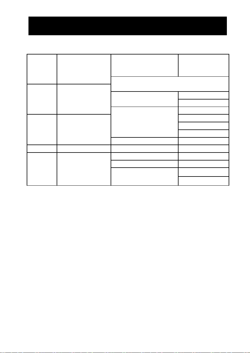
Unit Number
(W)
(X)
(Y)
(Z)
Key:
(W)
Base Type
(X)
Deck Option
(Y)
Control Option
(Z)
Coil Option
Reference
Part No
Description
(W)
Base Type
EXL95H
EXL95H
Intergral Base Unit
EXL96H
EXL96H
Split Base Unit
(X)
Deck option
CRV
1A6587
Carbonator Deck + Rotary Vane Pump
C
1A6615
Carbonator Deck + GPR10-15 Pump
CMD
1A6672
Carbonator Deck + Mag Drive Pump
XRV
1A6591
Non-Carbonator Deck + Rotary Vane Pump
X
1A6614
Non-Carbonator Deck + GPR10-15 Pump
XMD
1A6673
Non-Carbonator Deck + Mag Drive Pump
(Y)
Control Type
Z
1A6543
DFx Digital Control
A
1A6544
Eliwell Digital Control
B
1A6545
EXL95H Mechanical Control
1A6712
EXL96H Mechanical Control
(Z)
Coils
0
1A6671
0 Coil Pack
6
1A6670
6 Coil Pack
Model Numbering, Installation and Commissioning
5
Installation and Commissioning
The unit must be installed by a competent person, on a firm level surface capable of supporting the
weight of the machine when the bath is filled, and all connections made. Please ensure that the unit is
positioned at least 100mm from any other surfaces, as it is important that the ventilation openings in the
machine are not blocked and allow the free movement of air for both the carbonator & non-carbonator
version. Inadequate ventilation will shorten the life of the fridge system.
Locate a container beneath the bath overflow to prevent any water spillage as ice is formed in the bath,
and fill the bath with cold water until it comes out of the overflow.
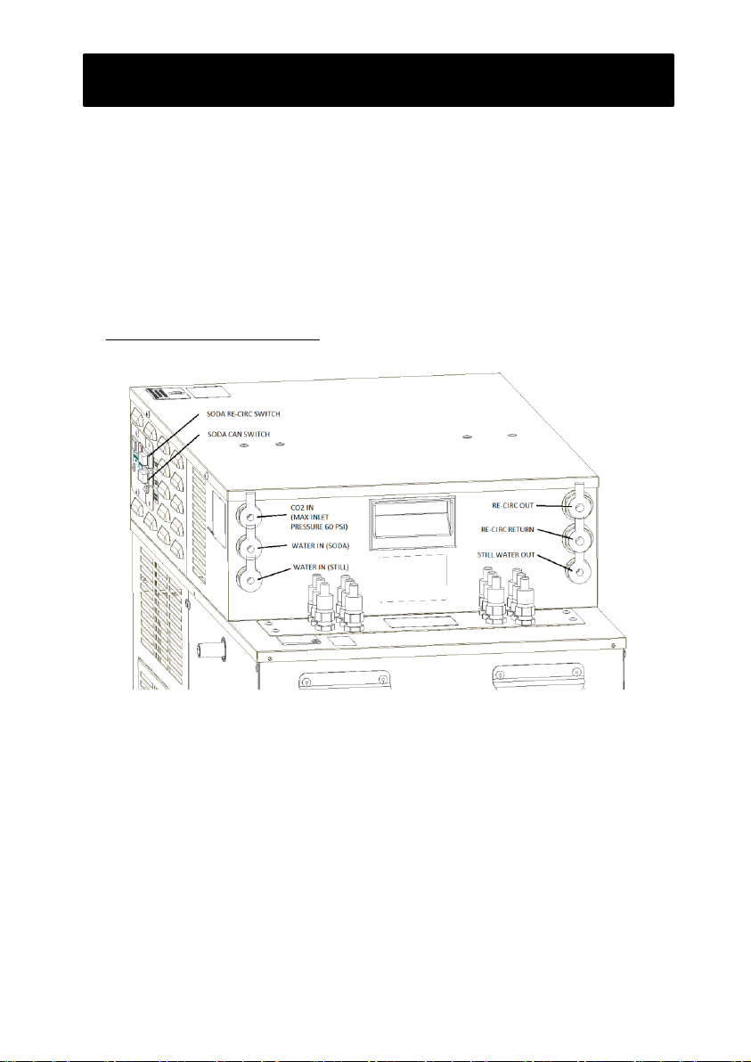
For the EXL95H/96H Carbonator Deck
Turn off the soda recirc pump and disable the can fill circuit by means of the 2 switches located on the
front of the unit. Important: Great caremust be taken on commissioning the machine when power
is applied to the unit. Power may now be applied to the machine to allow the fridge to form an ice bank
while the rest of the system is installed.
Connect the water inlet to a potable water supply, connect the soda recirc lines to the bulkhead
connectors, and then connect the CO2 inlet but do not turn on just yet.
Turn on the water supply and turn on the can fill circuit (black switch). Allow the can to carb can to fill
with water. The can fill pump will switch off once the can is full, this should take between 5-10 seconds.
Installation & Commissioning

6
Turn on the CO2 and purge the carbonator vessel by lifting the ring lever of the pressure relief valve on
top of the can, and let gas flow for up to 5 seconds.
Switch on the soda recirc pump (green switch) ensuring that the water supply is on. The rest of the circuit
should now be primed and as much air as possible removed from the circuit. The lifespan of the recirc
pump will be shortened if it is allowed to run dry for prolonged periods.
To achieve optimum carbonation, all air must be purged from the pipework, carbonator can, and the
soda recirc circuit. All air from the circuit will tend to be pumped back to the can, so it is suggested that
this be vented regularly while the circuit is being primed.
Optimum carbonation will only be achieved once the fridge has achieved normal working temperature
and there is ice present in the bath. It is also advisable to initially pull off approx. 1ltr –2litres of
carbonated water per dispense point to allow the carbonated water to circulate round the system.
For the EXL95H/EXL96H Non-Carbonator Deck
Connect the ‘still water in’coil to a potable water supply, connect the recirc lines to the bulkhead
connector and the ‘recirc in’ coil.
Connect your supply of soda water to the ‘soda in’ coil.
Power may now be applied to the machine to allow the fridge to form an ice bank.
Installation & Commissioning

7
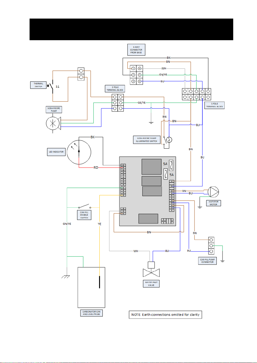
Schematics –EXL95H Base Wiring
1
2
3
4
5
6
G/Y
BR
COMPRESSOR
FAN OR
GLYCOL PUMP
BU
BU
BU
BR
WH
WH
WH
BU
BU
CONTROL
MODULE
IEC TO DECK
1
2
3
BNBU
BU
BN
BN
GN/YE
YE
BK
RD
LED
INDICATOR
NOTE: Earth connections omitted for clarity
BN
BU
BN
BU
GN/
YE
BN
BU
BN
to
CAN FILL PUMP
CONNECTOR
IEC FROM
BASE
TERMINAL
BLOCK
SODA RECIRC PUMP
THERMAL TRIP
SODA RECIRC PUMP
ILLUMINATED SWITCH
SODA RECIRC
PUMP
WATER INLET
VALVE
CARBONATOR CAN
AND LEVEL PROBE
GN/
YE
BN
BU
AGITATOR
MOTOR
5A
5A

8
Schematics –EXL96H Base Wiring
1
2
3
4
5
6
G/Y
BR
COMPRESSOR
FAN OR
GLYCOL PUMP
BU
BU
BU
BR
WH
WH
WH
BU
BU
CONTROL
MODULE
IEC TO DECK
1
2
3
BNBU
BU
BN
BN
GN/YE
YE
BK
RD
LED
INDICATOR
NOTE: Earth connections omitted for clarity
BN
BU
BN
BU
GN/
YE
BN
BU
BN
to
CAN FILL PUMP
CONNECTOR
IEC FROM
BASE
TERMINAL
BLOCK
SODA RECIRC PUMP
THERMAL TRIP
SODA RECIRC PUMP
ILLUMINATED SWITCH
SODA RECIRC
PUMP
WATER INLET
VALVE
CARBONATOR CAN
AND LEVEL PROBE
GN/
YE
BN
BU
AGITATOR
MOTOR
5A
5A

9
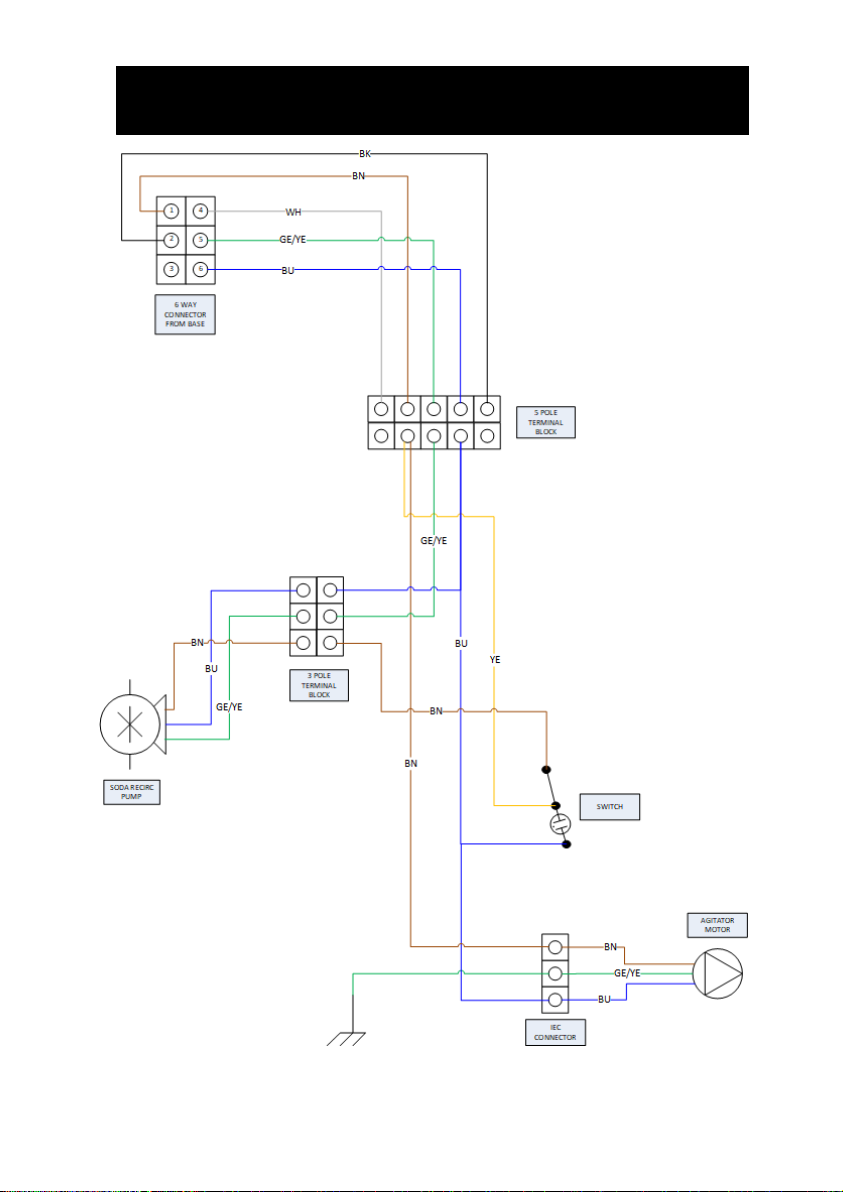
Schematics –EXL95H/96H GPR10-15 Pump Carb Deck Wiring
10
Schematics –EXL95H/96H RV/Mag Drive Pump Carb Deck Wiring
11
Schematics –EXL95H/96H GRP10-15 Non Carb Deck Wiring

12
Schematics –EXL95H/96H RV/MAG Drive Non Carb Deck Wiring
13
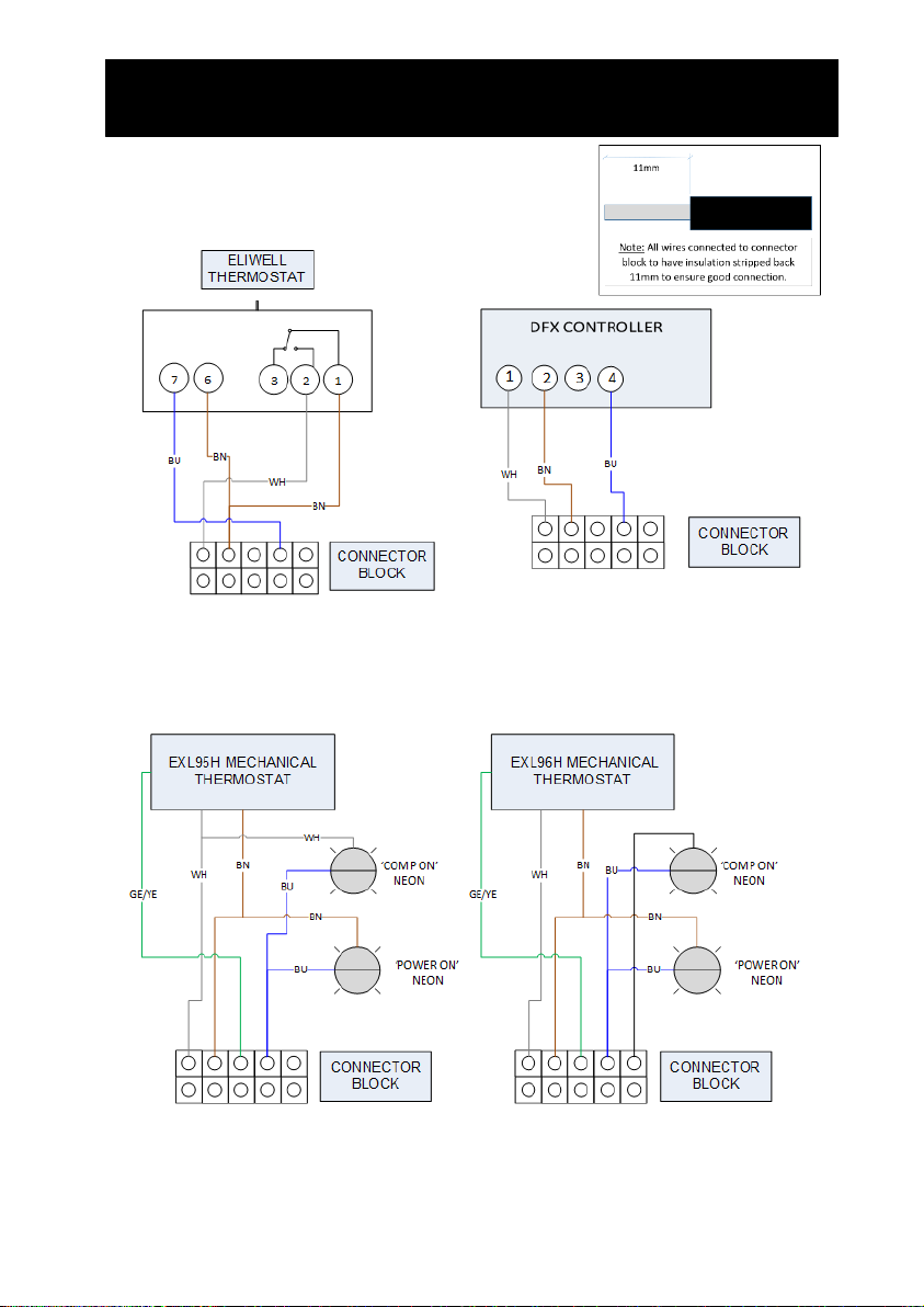
Schematics –Module wiring
14
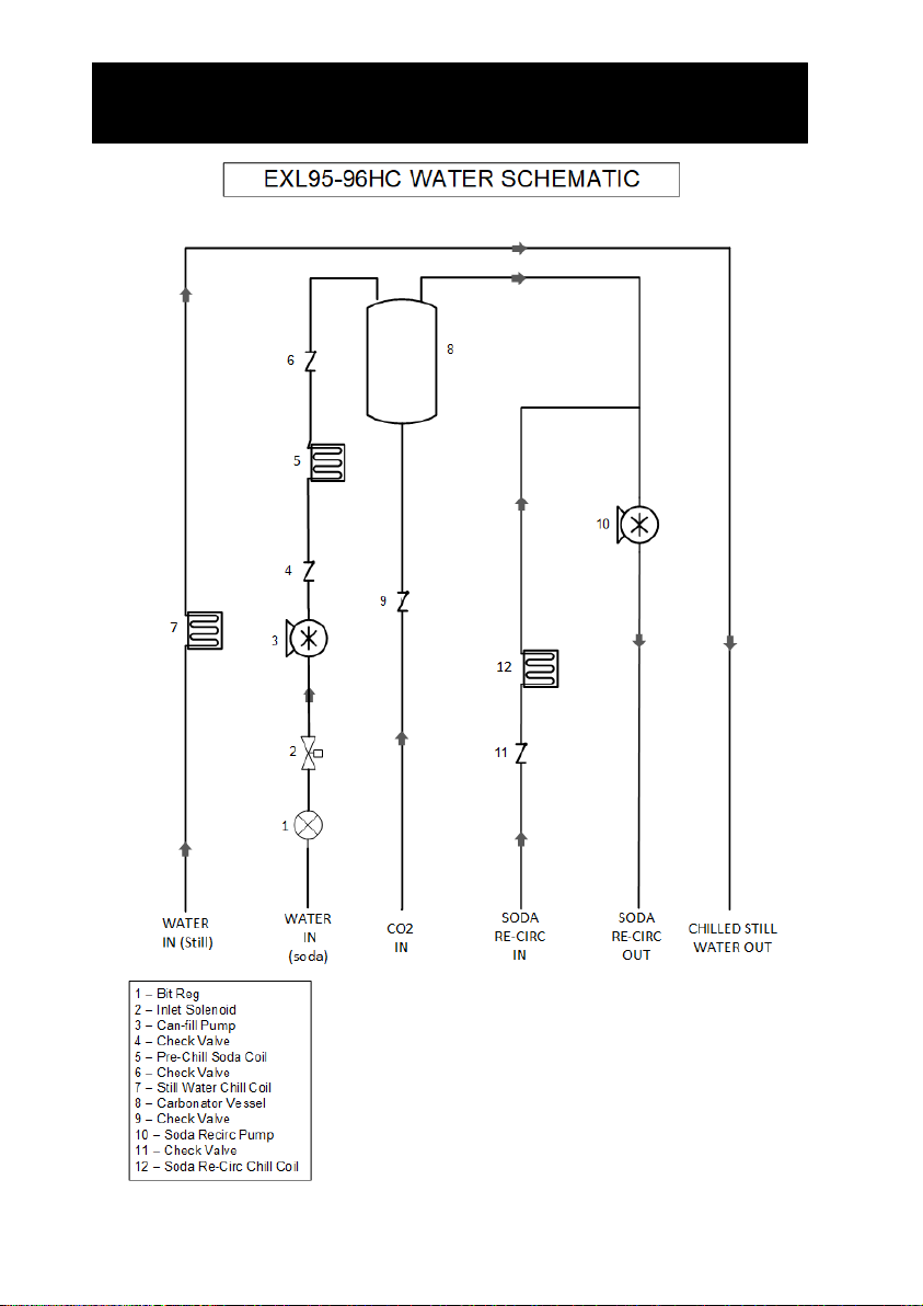
Schematics –EXL95H/96H Carb Deck Water Circuit

15
Schematics –EXL95H/96H Non Carb Deck Water Circuit
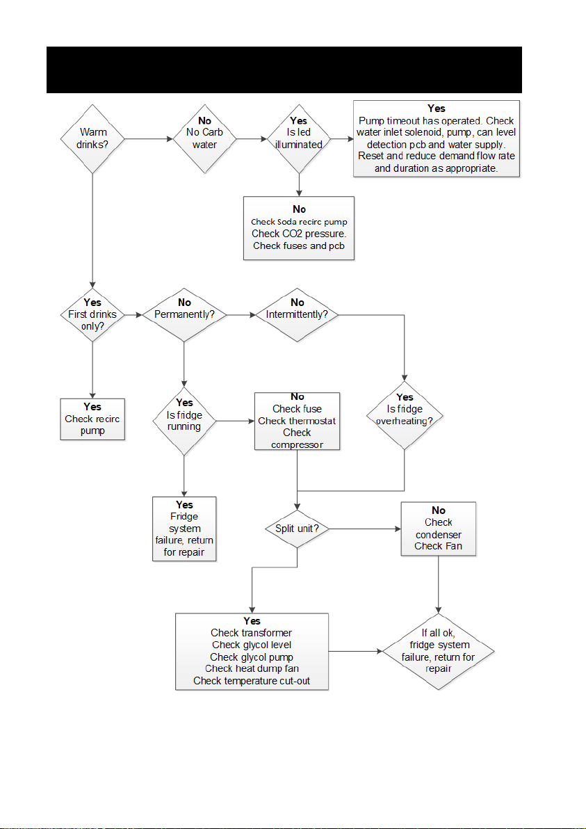
16
Fault Finding –EXL95H/96H Carb Deck

17
Fault Finding –EXL95H/96H Non Carb Deck

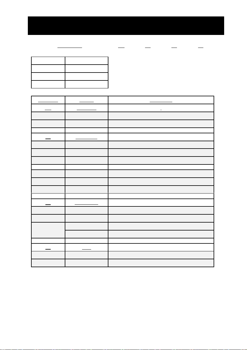
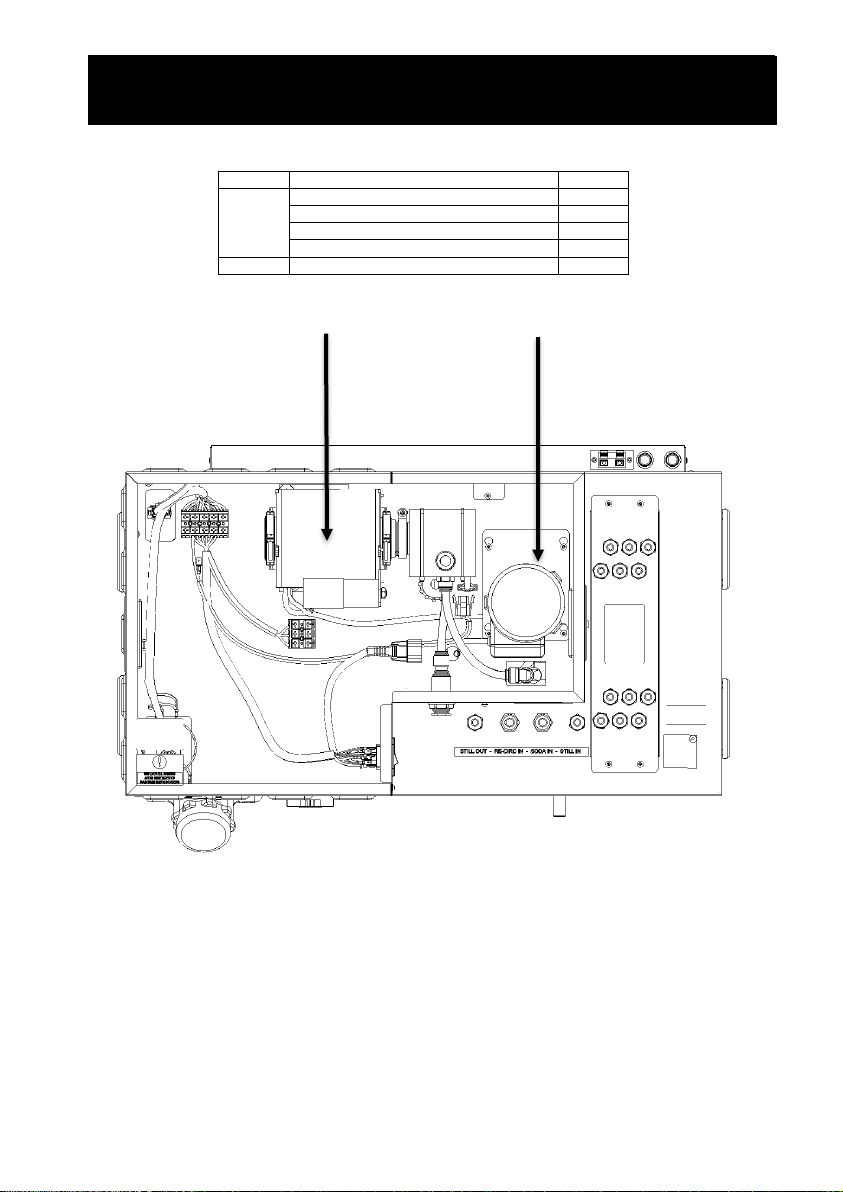
18
Item No
Description
Part No
1
PCB
1A5417
2
Soda recirc pump GPR10-15
1A6677
Soda recirc pump RV Motor Only
1A5368
Soda recirc pump RV Pump Head Only
1A5907
Soda recirc pump Mag Drive
3B7844
3
Water Inlet Solenoid
3B3641
4
Can fill pump motor only
3B3136
5
Can fill pump head assembly
3B6321
6
Agitator
3B3333
1
2
3
6
5
4
Replacement Parts –EXL95H/96H Carb Deck
19
Item No
Description
Part No
1
Soda recirc pump GPR10-15
1A6677
Soda recirc pump RV Motor Only
1A5368
Soda recirc pump RV Pump Head Only
1A5907
Soda recirc pump Mag Drive
3B7844
2
Agitator
3B3333
Replacement Parts –EXL65H Carb Deck
1
2
Replacement Parts –EXL55H Non Carb Deck
Replacement Parts –EXL95H/96H Non Carb Deck

20
Item No
Description
Part No
1
Condenser Fan Motor
CPART0045S
Control Modules
Mechanical Thermostat
Eliwell Control
Eliwell 1.5m Probe
DFx Control
1A6636
3B3472
3B4341
1A5625
1
Replacement Parts –EXL95H Base
This manual suits for next models
1
Popular Chiller manuals by other brands

Carrier
Carrier Aquaforce 30XA Series Operation instructions

Carrier
Carrier AquaEdge 19DV series Controls operation and troubleshooting

York
York YR owner's manual

Johnson Controls
Johnson Controls York YKEP Series manual

York
York YCAL0065 user manual

Trane
Trane Agility HDWA Installation, operation and maintenance


