2YORK INTERNATIONAL
TABLE OF CONTENTS
GeneralInformation .......................................................................................... 2
Typical Nomenclature ....................................................................................... 3
UnitComponents ............................................................................................. 4
CompressorComponents................................................................................. 5
OperationalLimitations..................................................................................... 6
Physical Data .................................................................................................. 8
Dimensions ...................................................................................................... 10
Electrical Data ................................................................................................. 12
Installation........................................................................................................ 16
WeightDistribution and IsolatorLocations........................................................ 18
WiringDiagrams .............................................................................................. 20
UnitControlsandOperation ............................................................................. 31
Display Keys.................................................................................................... 34
Status Key....................................................................................................... 39
Entry Key......................................................................................................... 42
ProgramKey.................................................................................................... 43
Clock Keys ...................................................................................................... 47
SelectionofReturnor Leaving Chilled Liquid .................................................... 50
Setpoints Keys ................................................................................................ 51
System Safeties .............................................................................................. 61
Print Keys........................................................................................................ 67
Unit On / Off Switch ......................................................................................... 74
CompressorCapacityControl........................................................................... 80
System Startup Checklist ................................................................................ 81
PreventativeMaintenance................................................................................. 86
Options ............................................................................................................ 88
TroubleshootingChart ...................................................................................... 106
TemperatureConversionTables ........................................................................ 110
GENERAL INFORMATION
GENERALDESCRIPTION
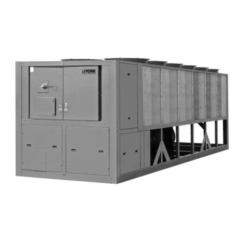
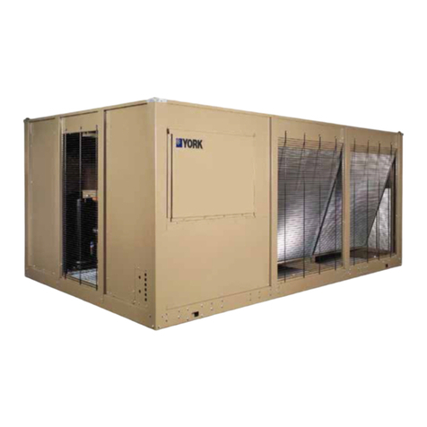
These packaged liquid chillers are completely self-
containedoutdoorunitsshippedready for final job instal-
lationrequiring onlyliquid connections,power and con-
trol wiring. They are designed primarily for central sta-
tion air conditioning applications with normal installa-
tions being on roof-tops or on ground level beside the
building.
CODESTATUS
Theunitsaredesignedin accordance with UL(200,230,
460-3-60),N.E.C., ASHRAE/ANSI STANDARD 15, and
ASME Codes.

