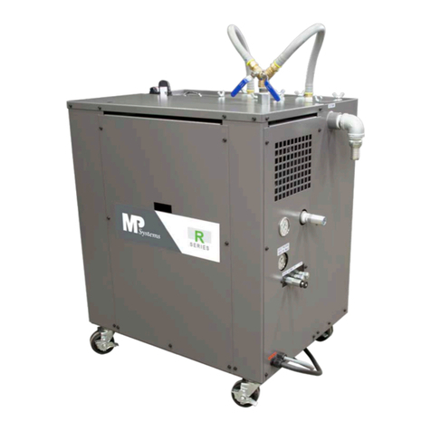
MP Systems PURGE Series User manual

(Purge Operator) R04
INSTALLATION, OPERATION, & MAINTENANCE MANUAL
MP Systems - 34 Bradley Park Road, East Granby, CT 06026 USA
PURGE Series

(Purge Operator) R04
MP SYSTEMS is committed to delivering
quality products and providing maximum
productivity and uptime. Our engineering
team is diligent in eliminating high
maintenance issues associated with
machine tool accessories, to allow better
performing equipment for your business.
Thanks to our quality components, dedicated engineers, sales team and
manufacturing personnel, MP SYSTEMS high pressure coolant systems &
accessories are low maintenance and longer lasting. MP SYSTEMS prides
itself on building and supporting a dependable product.
Our team works closely with CNC machine tool manufactures, distributors
and customers to provide excellent customer service. These relationships
facilitate superior application experiences. Our goal is to help make you
more productive with less downtime, decreased cycle times, improved tool
life and more parts out the door.

(Purge Operator) R04
PURGE SERIES INSTALLATION, OPERATION, MAINTENANCE MANUAL
DOCUMENT PART #: B PURGE OPERATOR
Revision
Description
Date
Issued
Proofed By:
00
Original
04/25/19
B. Jalbert
01
•Purge Drive Tuning Instructions
Added
•Add 1 ¼” Hose to Install Kit
•Add Mounting Bracket to Install
Kit
9/9/19
02
•Update PLC screens to match
V6.20
•Removed Drive Tuning
Instructions
•Add info on 480/400V system
6/4/20
B. Jalbert
03
•Update dip tube info and quick
start guide details. Removed
settings for FM5/8 & Manifold.
Added filter selection guide.
6/23/21
K. Quintin
04
•Fixed info on 480VAC specs
•Updated quick start guide and
install info.
•Updated start/stop mode of
operation.
•Updated PLC settings
3/28/22
K. Quintin

(Purge Operator) R04
Table of Contents
1. Introduction....................................................................................................................... 1
1.1. Symbology ................................................................................................................. 2
2. Safety Measures................................................................................................................ 3
2.1. General Rules............................................................................................................. 4
2.2. Prevention of Mechanical Risks ............................................................................... 4
2.3. Prevention of Electrical Risks................................................................................... 4
3. Intended Uses ................................................................................................................... 5
3.1. Why the Purge Works................................................................................................ 5
3.2. Features and Benefits ............................................................................................... 6
3.3 Considerations and Explanations............................................................................. 7
4. Specifications ................................................................................................................... 9
4.1. Electrical Specifications............................................................................................ 9
4.2. Mechanical Specifications ........................................................................................ 9
4.3. Floor Layout..............................................................................................................10
5. Moving & Storage ............................................................................................................11
5.1. Delivery Checks........................................................................................................11
5.2. Transport & Carriage................................................................................................11
5.3. Storage......................................................................................................................11
6. Installation........................................................................................................................12
6.1. Install Kit Components.............................................................................................13
6.2. Recommended Tools for Installations ....................................................................13
6.3. Electrical Installation................................................................................................15
6.3.1. Selecting Voltage...............................................................................................15
6.3.2. Power Harness Installation...............................................................................16
6.3.3. Control Signal Installation (Optional)...............................................................17
6.4. Inlet Installation ........................................................................................................18
6.4.1. Inlet Suction Dip Tube.......................................................................................18
6.5. Return Installation and Hose Routing.....................................................................21
6.5.1. Return Installation .............................................................................................21
6.5.2. Hose Routing .....................................................................................................21
6.6. Filling the Tank .........................................................................................................22
6.6.1. Feed Pump Installation & Priming Procedure..................................................22
7. Operation..........................................................................................................................23
7.1. PLC Set Up and Settings..........................................................................................23
7.1.1. PLC Initial Set Up...............................................................................................23
7.1.2. PLC Settings ......................................................................................................24
7.1.3. Alarms ................................................................................................................32

(Purge Operator) R04
8. Maintenance.....................................................................................................................34
8.1. Routine Maintenance................................................................................................34
8.1.1. Filter Bag Replacement.....................................................................................35
8.1.2. Filter Bag Selection ...........................................................................................36
9. Spare Parts.......................................................................................................................38
10. Schematics and Diagrams...........................................................................................39

1
1. Introduction
This manual contains instructions for installation, operation and maintenance of
the Purge Full Flow Filtration System, as well as indicating residual risk associated with
it. This manual has been specifically compiled and produced to enable easy and safe
use by appropriate personnel.
All associated rights, in particular the rights of reproduction, publication, and
translation, are retained by the producer in accordance with authors rights.
MP SYSTEMS does not accept responsibility for any inaccuracies contained in
this manual, whether due to errors in printing or transcription. It furthermore reserves
the right to carry out such modifications to its products as it considers necessary and/or
useful, without compromising their essential characteristics.
MP SYSTEMS does not accept responsibility for improper use of the equipment,
unauthorized modifications, or non-observance of the instructions contained in the
manual. This manual must be kept in a safe place and made available to personnel
qualified to use and maintain Purge Systems.

2
1.1. Symbology
Symbology contained in this manual.
DANGER: Indicates possible danger. Failure to heed this warning carries a
risk of accident or injury.
DANGEROUS VOLTAGE: Indicates dangerous voltage. Failure to heed
this warning carries a risk of injury or death.
WARNING: Indicates a possible danger situation. Failure to heed this
warning carries a risk of injury.
INFORMATION: Indicates important information or advice on the use of
the machine.
FLAMMABLE: Indicates possible flammable material.
LOCK-OUT/TAG-OUT: Lock-Out/Tag-Out Purge Series before service can
be done.

3
2. Safety Measures
MP SYSTEMS disclaims all responsibility for non-observance of the
instructions and advice contained in this manual. It furthermore disclaims all
responsibility for damage caused by improper or inappropriate use of the machine
or by modifications made without authorization.
These safety instructions contain all the general rules that must be
observed during commissioning, operations and all periods of attendance to
the machine.
It is essential that these instructions are supplied and always available to the
installer, competent operators, and authorized maintenance personnel.
The following basic instructions must be observed when using the Purge Series:
•Operation and maintenance must be carried out only by qualified
personnel following the instructions contained in this manual.
•Always keep a copy of this manual near the machine.
•Carry out routine maintenance operations with great care; have worn or
damaged parts replaced by qualified personnel and use original parts or
those recommended by MP SYSTEMS.
•To function correctly, and for operator security, the Purge Series must be
operated with all panels in place and secured.
•Dangerous voltage contained within Purge Series. Before carrying out
any operations on Purge Series, ensure that the electrical supply has
been switched off.
•Operating Purge Series with safety protection removed is strictly
forbidden.
•Before installing Purge Series ensure operating conditions are suitable for
intended use.
MP SYSTEMS disclaims all responsibility for damage to person(s) or
things resulting from non-standard assembly of the machine or from re-
use of its individual components. Unauthorized replacement or removal
of one or more parts of the machine is forbidden.

4
2.1. General Rules
The Purge Series has been designed and constructed in such a way to minimize
any possible cause of danger to the operator and their surroundings. However,
residual risk remains and can arise through improper use of the machine and can be
of various types:
•Risk due to escaped coolant/cutting fluid.
•Risk due to excessive noise caused by operating outside permitted limits.
•Risk of accidents caused by scraping against edged sheet metal profiles.
2.2. Prevention of Mechanical Risks
In operation, the Purge Series contains some moving parts. These parts constitute a
possible source of danger to the operator, therefore to avoid any possible danger it
is necessary to observe the following operational rules:
•Before removing any panels/guards, ensure electrical supply to the
machine has been switched off.
•Never start the Purge Series with any panel/guards removed.
•The additives present in coolant/cutting fluid may have a corrosive action
that can irritate the skin and eyes.
oAlways wear gloves & eye protection when handling
coolant/cutting fluid.
2.3. Prevention of Electrical Risks
When power to the machine is switched on, the machine is a source of danger,
especially if the basic safety rules are not followed. In order to avoid any possible
danger, it is necessary to observe the following basic operation rules:
•When making electrical connections to the Purge Series, observe state
and federal electrical codes or those otherwise in force. Observe the
technical & electrical supply conditions imposed by the power supply
companies.
•Before carrying out any work on the Purge Series, switch off the electrical
supply at the main isolator.
•Work on the Purge Series must only be carried out by authorized
personnel.
•Always replace worn out or defective components.
•Before working on electrical equipment always read the manual that
contains the machines circuit diagram.
•Always make sure there is no electric power to the equipment.
•Check to ensure the machine is earthed before powering on the Purge
Series.
•Check all electrical connections and connecting cables are well insulated
and replace any cables that are evidently worn or damaged.
•Be sure to use power cables supplied by MP SYSTEMS or that have
been approved by MP SYSTEMS.

5
3. Intended Uses
3.1. Why the Purge Works
Without the Purge
•Coolant and chips run through the machine and go into the “dirty side” of
the machine tank.
•Coolant flows from dirty side to clean side through a screen, which
collects chips and debris.
•As the screen gets blocked, coolant can no longer flow into the clean
side, starving the pumps.
•The loss of coolant can cause poor part finish, increase tooling wear, out
of tolerance parts, and alarming out in the middle of a part cycle. In some
cases, there is no alarm for loss of flood coolant, which could allow the
problem to cause more and more damage until it is found and resolved.
•To resolve the issue properly, the machine must be shut down, the tank
drained and removed from under the machine, chips removed, and
screens cleaned. Everything then must be put back together; the tank
moved back into place, hoses reconnected, pumps plugged back in, tank
refilled with coolant, and then the machine can be turned on and run
again, repeating the cycle.
With the Purge
•Coolant comes out of the tool or nozzle, falls down with chips, (goes
through chip conveyor), and goes into a collection funnel in the “dirty side”
of the tank.
•The Purge system pulls in coolant and chips from the funnel at a rate
faster than is being provided. This creates a difference in fluid level
between the inside and the outside of the funnel, pushing chips towards
the Purge collection dip tube.
•The fluid with chips is pumped through a set of filters that are selected
based on material and cutting process, and can be easily changed to
meet the needs of different part programs in the future.
•The chips are collected in the filter bags and the coolant flows back to the
clean side of the tank.
•The volume of fluid coming in to the clean side of the tank exceeds the
volume being pumped out, again, creating a fluid height difference,
pushing all debris in the tank towards the Purge collection dip tube and
away from the pumps, while also providing the pumps with more than
enough coolant so they never pull in air.
•When the Purge filters are dirty, the Purge will alarm out but will not stop
the machine tool. The Purge can then be shut down to replace the filters
quickly and easily, which results in more coolant up time.

6
3.2. Features and Benefits
Purge Features:
•30-60 GPM (gallons per minute) programmable flow rate
•Qty 4 - 5µm (micron) Standard Filtration (#2, 7” X 32” bags)
•Rugged cast pump with 3HP inverter duty motor
•Pump delivers a constant flow –even as filters begin to clog
•Versatile: Accepts a vast array of filtering elements
•Debris Collection Device to capture chips and direct towards inlet
•(Optional for custom applications –contact MP Systems)
•Easy Installation with complete parts kit
•Status Indicator light and HMI Screen
•3 Phase breaker and wiring kit to easily pull power from machine.
•Auto start on power up feature or scheduled clock run function
•Hour counters for filter run time vs machine run time (optional)
•2 Year Parts Warranty*
Purge Benefits:
•Clean coolant lasts significantly longer
•Less wear & tear on machine and components
•Greatly extend time between tank cleanouts
•Prevent unexpected coolant related shutdowns
•Overall cleaner machining environment
•Improved part quality and tool life
•Excess reverse flow prevents chips from building up on the screens.
•Customer can continue to run machine tool while changing purge filters
•Hour counter can be implemented to develop filter change schedule
•Provides constant flow of clean coolant to prevent starvation of flood and
high-pressure pumps.

7
3.3 Considerations and Explanations
•The Purge is not intended to be a replacement for a chip conveyor.
•The system is intended to filter out fine debris that is carried with the coolant
through the conveyor or screen basket perforations.
•Debris being filtered by the purge should be no larger than ¼” for standard models.
•The suction inlet can be placed directly after filtering (500µm or lower) conveyors
•For non-filter type conveyors, it is recommended that a perforated screen basket
be used at the output of the conveyor to capture all debris larger than ¼” for
standard models and the purge suction inlet placed after the screen basket.
•Works with water-based coolants or cutting oils. Cutting oils may require different
flow rates to accommodate difference in viscosity and flow through tank screens.
•A Debris collection device is not always required when installing a purge. They are
custom, made to order per application items. Contact MP Systems directly for
more details.
•The suction inlet must be placed where it can capture debris as it’s still suspended
in the fluid. If the debris is allowed to settle to the bottom of the tank, it will remain
there and require manual cleanout once enough accumulates.
•The Purge comes with standard 5µm nominal rated polyester felt steel ring filter
bags. There are several other options for filter media depending on the
application. Please contact MP systems to discuss more.
•The system should always be on and filtering when machining. There are several
ways to run the filter system, most do not require any additional wiring. Factory
settings are to start/stop the purge by pressing the buttons on the HMI display. A
setting can also be enabled to allow the purge to run automatically when powered
up. Another option is to run the filter on a scheduled Real time clock timer. Refer
to the quick start guide and PLC settings section for more information.
•The alarm circuit interface with the machine is not typically required but is available
if desired. Typically, customers will rely on the status indicator light on the control
box to tell them when the purge requires maintenance. This works for most
customers but if wanted, an alarm signal can be interfaced with the machine tool.
Refer to the interface drawing for more explanation.
•If desired, an interface cable can be wired into the machine control to receive a
“run” signal and track number of hours the run signal was sent to the filter, vs the
actual time the filter was run. This can be helpful for management to ensure that
the filters are being run and maintained properly and not allowed to sit idle while
debris accumulates in the coolant tank.
•The “Debris Collection Device” referred to is a type of perforated screen basket
that captures chips larger than ¼” before they get sucked into the filtration system.
The DCD can also be designed as a “funnel” to ensure all debris is directed
towards the suction inlet.
•Bag life can be tracked by the hour counter. Note hours when installing a fresh set
of filters and note hours when the filters are clogged and need to be replaced. This
can provide an average time between maintenance.
•Filter change warning and alarm can be based on a settable max pressure or a
settable hour counter.
•Small particles and “sludge” like debris will typically “blind off” or “coat” the inside of
the filter bag forming a layer of “cake” and not actually accumulate the full available
volume of the bag. As the bag clogs, the incoming pressure increases until the
pressure reaches the max allowable pressure that can be programmed in the PLC.

8
The max allowable pressure for this type of filter is 25psi. If longer filter life is
desired for applications like this, there are alternative filter media options that will
help retain more volume of fine/sludge like debris.
•While allowing bags to run up to a higher pressure may provide more time between
filter changes, it may also make filter changes slightly more difficult since the fluid
will not drain out of the bag as easily. Try starting with 15psi and either increasing
the max pressure or decreasing depending on how filter change experience is.
•Larger particles that are more porous as they accumulate will tend to fill the volume
of the filter bag more. These chips are sometimes so porous that they do not
create enough detectable back pressure before the bags are completely full. For
applications like this, we recommend using the filter hour tracker function to alert
the customer when to change the bags.

9
4. Specifications
MP SYSTEMS equipment ships with an identification label. The label is located on the
control box on the front of the machine.
*Information listed on Identification Label:
•Pump Type
•Serial Number
•Build Date
•Operating Voltage (208-230VAC) (Optional 480V)
•FLA (Full Load Amps). Largest Load, for determining power service
requirements.
4.1. Electrical Specifications
MODEL
FLA @
208/230VAC
(Standard VAC)
kVA
FLA @
480VAC
(USEABLE
@400V +/- 5%)
CONTROL
SIGNALS
ALARM
CIRCUIT
Purge
8.5*
3.2
4.0*
Fused
24VDC
NC/NO
COMPONENT
/ ACCESSORY
FLA @ 208/230VAC
(Standard VAC)
FLA @ 480VAC
(USEABLE @400V +/- 5%)
HP
RPM
Feed Pump
8.5*
4.0*
3
3600
4.2. Mechanical Specifications
MODEL
LENGTH
(in)
WIDTH
(in)
HEIGHT
(in)
CAPACITY
(gal)
FLOW
RATE
Purge
28
24
36
30
30-60GPM

10
4.3. Floor Layout

11
5. Moving & Storage
5.1. Delivery Checks
When taking delivery of a machine, ensure that the
machine has been transported in the correct position.
Carefully check the physical condition of the box for
any signs of external damage. If there is evidence of
damage, remove the packaging to ensure there is no
damage to the contents of the skid. In case of
damage, DO NOT accept the goods and
immediately inform MP SYSTEMS. If you are unsure if
there is damage to the contents and accept delivery, you must write “Damaged” on
the delivery receipt.
In the event of irregularities during transit, the freight company will bear the full
responsibility for any damage suffered.
5.2. Transport & Carriage
The machine must be transported in a vertical position, as shipped. The tank MUST BE
EMPTY before moving. The Purge Series has been constructed to be moved by fork
truck.
The machine must be moved in such a way as to avoid the risk of damage.
Do not attempt to lift the machine with equipment that is inadequate or unsuitable,
especially with equipment that is too small for overall weight of machine. Refer to
Section 4.2. Mechanical Specifications for unit weight.
Only trained and licensed Fork Truck operators may transport this machine. MP
SYSTEMS is not responsible for any damage caused by unauthorized use.
WARNING: Do not transport machine with fluid in tank.
5.3. Storage
The Purge Series must be stored in a cool and dry environment,
avoiding all extreme conditions including freezing conditions. All coolant
must be drained from machine before being stored. If utilizing water
based coolants, the system must be flushed before storage, please
refer to the coolant manufacturer for correct flushing agent. Removing
all coolant from the system will ensure coolant does not become
contaminated while in the system. Contaminated coolant may lead to malfunctions.
Not properly draining/flushing Purge Series before storage can lead to
bacterial growth, which will contaminate any coolant it comes into contact
with. Contaminated coolants effectiveness is also greatly reduced.

12
6. Installation
All MP SYSTEMS Purge Series are shipped on wooden pallets designed for the safe
transport of the Purge Series Full Flow Filtration System. A large MP SYSTEMS box
protects the Purge from any unnecessary damage during transportation. If there is
visible damage from transportation, refer to Section 5.1 Delivery Checks.
•Typical installation time required: 4 Hours
•Plumbing kit includes inlet, and return dip tubes, hoses, and clamps.
•3 Phase power kit w/circuit breaker provided to pull power directly from machine.
•Purge can be set to automatically run when powered on; or with scheduled timer.
•Status indicator light and HMI removes need for alarm interface with machine.
•May require hole saws, see appendix in back for more information.
•The Purge requires roughly 24” x 24” of floor space that is located as close to the
machine tank’s coolant pump(s) as possible to allow for proper return flow.
•The feed pump can be mounted remotely and should be located close to the inlet
suction dip tube.
•The pump can either sit directly on the floor or be mounted on the coolant tank if
space allows.
•Purge Electrical panel and Manifold locations can be swapped if required for
proper return hose direction.

13
6.1. Install Kit Components
COMPONENT
QUANTITY/LENGTH
Return Dip Tube
1
Inlet Dip Tube
1
Power Harness
1
Circuit Breaker
1
1 ¼”” Hose
25’
2 ½” Hose
10’
Hose Clamps
5
T-Bolt Hose Clamp for Return
1
Dip Tube Mounting Brackets
2
Return Hose Clamp
1
Operation Manual
1
5MC Steel Ring Filter Bags
4
6.2. Recommended Tools for Installations
•Phillips (Cross) Head Screwdriver
•Flat Blade Screwdriver
•Electric Drill
•7/8” UniBit (Step Drill)
•1 3/4” & 3” hole saw, or equivalent conduit punch may be required.
•12” Pipe Wrench (Minimum)
•Metric Hex Keys
•Teflon Pipe Tape / Liquid Pipe Sealant
When installing MP Systems products, the correct location of the dip tubes is important
to a successful install. The best way to do this is to use a preexisting hole in the tank
can be used to pass the various pipes through the tank top. This is not only quick and
easy, but also gives you a perfect window to be able to see what is going on in your
tank for troubleshooting. Sometimes, this is simply not an option, and a hole must be
drilled in the tank.
If you find yourself in a pinch, most hardware stores like Home Depot or Lowes will have
the required hole saws available, you will want to find a bi-metallic hole saw like a
Milwaukee or Lenox depending on which store you go to. These tend to be the best
option in a hurry, however they will wear out, so if you have a lot of holes to drill, it may
be wise to purchase more than one.

14
If you know ahead of time that you will need them, then they can be ordered from
McMaster, or MP Systems stocks and can ship a kit with all the necessary components.
HIGH PRESSURE
PURGE
CDR
PIPE SIZE
HOLE SAW
McMaster
MP Systems
X
X
X
1 1/4"
1 3/4"
3789A29
AK HOLE SAW KIT
X
1 1/2"
2"
3789A33
AK HOLE SAW KIT
X
2"
2 1/2"
3789A39
AK HOLE SAW KIT
X
2 1/2"
3"
3789A45
AK HOLE SAW KIT
X
X
X
ALL
ARBOR
3789A61
AK HOLE SAW KIT
X
X
X
ALL
PIN 3/16 X 2
97395A618
AK HOLE SAW KIT
Cutting a hole in sheet metal seems like a common task,
however doing it right will not only be safer, but can also
improve tool life, cut speed, and cut quality (clean vs. jagged
edges).
1. Start by measuring twice. Use the green pipe clamp
for the dip tube you are installing to help layout where
the hole needs to be drilled, as well as where the
fasteners will need to go for the clamp. Use a center
punch to locate the holes and prevent drill drift.
2. Use the appropriate size drill to make a pilot hole in
the center of the cut. *NOTE* Only the drill should be
used at this point, do not use the drill bit while
attached to the hole saw. When the drill breaks
through, you can damage the hole saw by “punching”
the sheet metal and breaking or bending the teeth.
3. Install the blank pin in the arbor, then thread on the
hole saw. (In a pinch, an old drill bit installed
backwards can work as a guide too) Be sure to set
your drill to low speed and change from drilling to
torque mode.
4. Apply cutting fluid and begin cutting, feathering the
trigger to maintain a moderate speed.
5. Be sure to continuously add cutting fluid to keep the
hole saw cool and lubricate the cut.

15
6.3. Electrical Installation
Before connecting electrical power, pay close attention to the electrical data on machine
plate. Ensure that the voltage of the power supply is compatible with that specified on
plate. All installation work must be carried out by qualified personnel. Always consult
machine tool wiring diagram before connecting power.
LOCK OUT/TAG OUT any and all power disconnect switches
before performing any work on equipment.
Be sure to observe local and federal electrical codes in effect.
Observe the technical supply conditions imposed by the power
supply company.
6.3.1. Selecting Voltage
Many large industrial facilities run on 480v 3phase @ 60Hz electricity. Most machine
tools in the United States require a step down transformer as the machine tools,
typically, run on 200 +/- 10% VAC. 208-230v is the standard voltage for MP Systems
units. (Optionally, 480V units can be purchased, voltage cannot be changed in the field)
Utilizing machine tool voltage makes lockout/tag-out far easier and allows it to comply
with most local regulations.
Power can either be pulled from a separate drop, or from the machine tool using the
provided circuit breaker in the installation kit if the machine tool breaker allows.
Other manuals for PURGE Series
1
Table of contents
Other MP Systems Chiller manuals
Popular Chiller manuals by other brands

Haier
Haier CA0070AANB Installation & operation manual

Pfannenberg
Pfannenberg CCE 6101 Operating and maintenance instructions

A2B Accorroni
A2B Accorroni RPE Series manual

Zip
Zip HydroTap G4 user guide

Nordcap
Nordcap 433000003 user manual

Carrier
Carrier HERMETIC ABSORPTION LIQUID CHILLER 16JB installation instructions

AERMEC
AERMEC FCS 22 user manual

Liebert
Liebert Process Fluid Chiller PS048A Specification sheet

Daikin
Daikin EWAD TZ Installation, operation and maintenance

Solid State Cooling Systems
Solid State Cooling Systems THERMOCUBE 200 product manual

TICA
TICA TAS-AH Series Installation & operation manual

CLIVET
CLIVET WSH-XEE2 Series Installation and operating manual