Booxt GOES 300S User manual
2007 GOES HI-PERF 300S
SERVICE MANUAL
FOREWORD
This service manual is designed primarily for use by certified Goes Master Service
Dealer technicians in a properly equipped shop and should be kept available for
reference. All references to left and right side of the vehicle are from the operator's
perspective when seated in a normal riding position.
Some procedures outlined in this manual require a sound knowledge of mechanical
theory, tool use, and shop procedures in order to perform the work safely and correctly.
Technicians should read the text and be familiar with service procedures before starting
the work. Certain procedures require the use of special tools. Use only the proper tools
as specified.
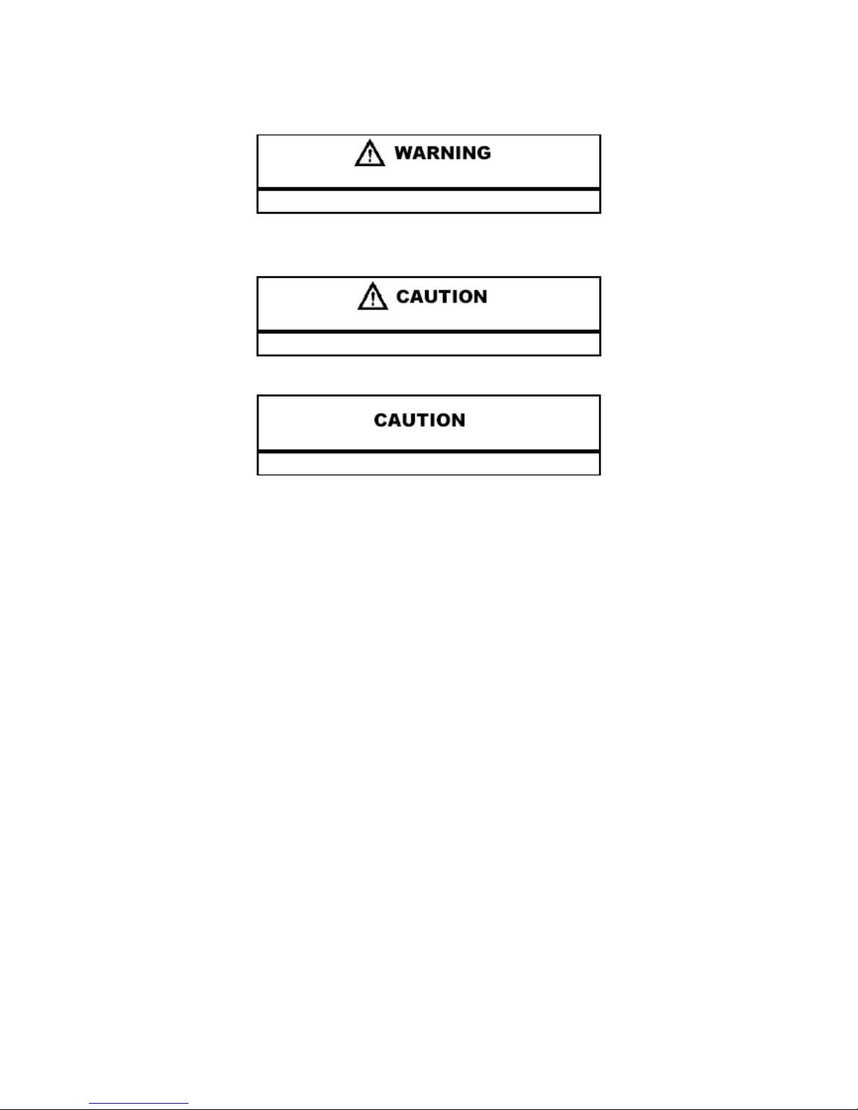
UNDERSTANDING MANUAL SAFETY LABELS AND DIRECTIONS
Throughout this manual, important information is brought to your attention by the following symbols:
SAFETY ALERT WARNING indicates a potential hazard that may result in severe injury or death to the operator, bystander
or person(s) inspecting or servicing the vehicle.
SAFETY ALERT CAUTION indicates a potential hazard that may result in minor personal injury or damage to the vehicle.
CAUTION indicates special precautions that must be taken to avoid vehicle damage or property damage.
NOTE:
NOTE provides key information by clarifying instructions.
IMPORTANT:
IMPORTANT provides key reminders during disassembly, assembly and inspection of components.

1
GENERAL INFORMATION 1
MAINTENANCE 2
CVT 3
ENGINE 4
TRANSMISSION 5
FUEL SYSTEM 6
BODY / SUSPENSION / STEERING 7
BRAKES 8
ELECTRICAL 9
2 4

GENERALINFORMATION
CHAPTER 1
GENERAL INFORMATION
INFORMATION . . . . .……………... . . . . . . . . . . . . . . . . . . . . . . . . . . . . . . . . . . . . . . . . . . 1.2
ENGINE SERIAL NUMBER LOCATION . . . . . . . . . . . . . . . . . . . . . . . . . . . . . . . . . . . . . 1.2
VEHICLE IDENTIFICATION NUMBER LOCATION. . . . . . . . . . . . . . . . . . . . . . . . . . . . . 1.2
GENERAL SPECIFICATIONS . . . . . . . . . . . . . . . . . . . . . . . . . . . . . . . . . . . . . . . . . . . . . 1.3
GENERAL SPECIFICATIONSMODEL: GOES 300S . . . . . . . . . . . . . . . . . . . . . . . . . . . .1.3
GENERAL VEHICLE INSPECTIONAND MAINTENANCE . . . . . . . . . . . . . . . . . . . . . . . .1.4
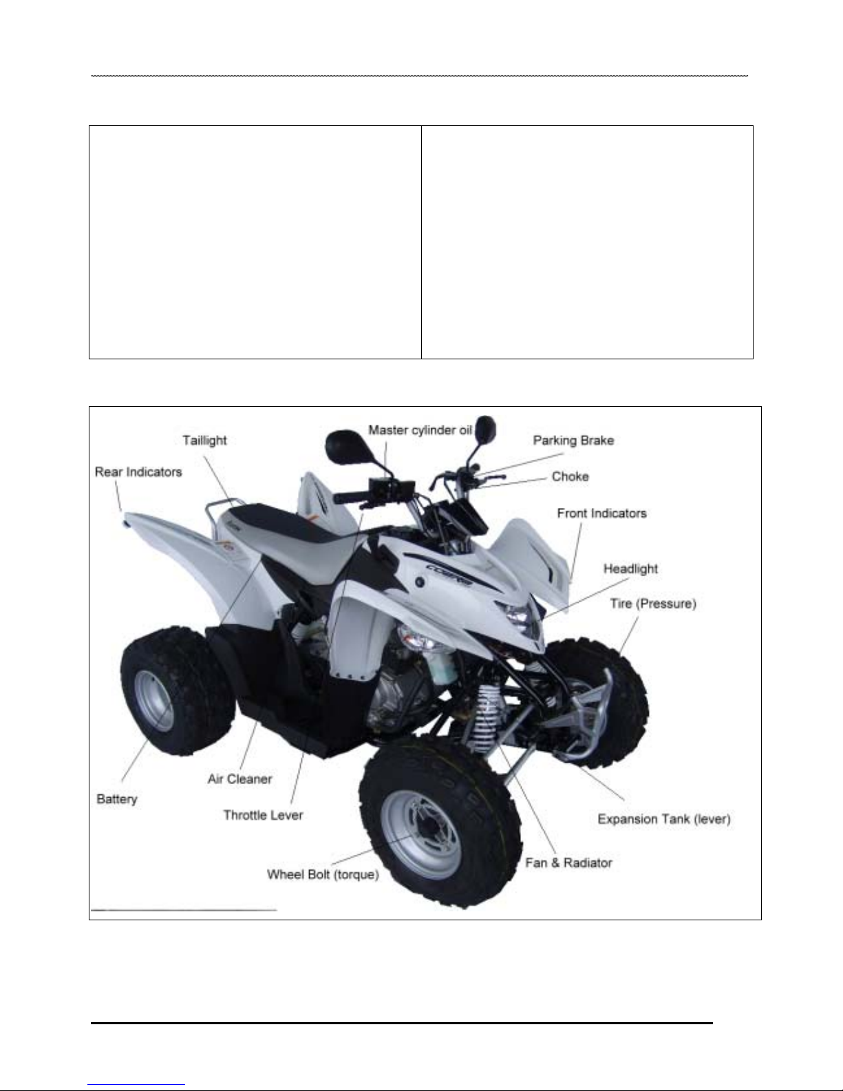
VEHICLE COMPONENT INSPECTION LOCATIONS………………………………………1.4
GENERAL SPECIFICATIONSMODEL: TREETRENTAR 330 ON ROAD . . . . . . . . . . . ...1.5
GENERAL VEHICLE INSPECTIONAND MAINTENANCE . . . . . . . . . . . . . . . . . . . . . . . . 1.6
VEHICLE COMPONENT INSPECTION LOCATIONS . . . . . . . . . . . . . . . . . . . . . . . . . . .. 1.6
GLOSSARY OF TERMS . . . . . . . . . . . . . . . . . . . . . . . . . . . . . . . . . . . . . . . . . . . . . . . . . 1.7
1.1
GENERALINFORMATION
6MODEL INFORMATION
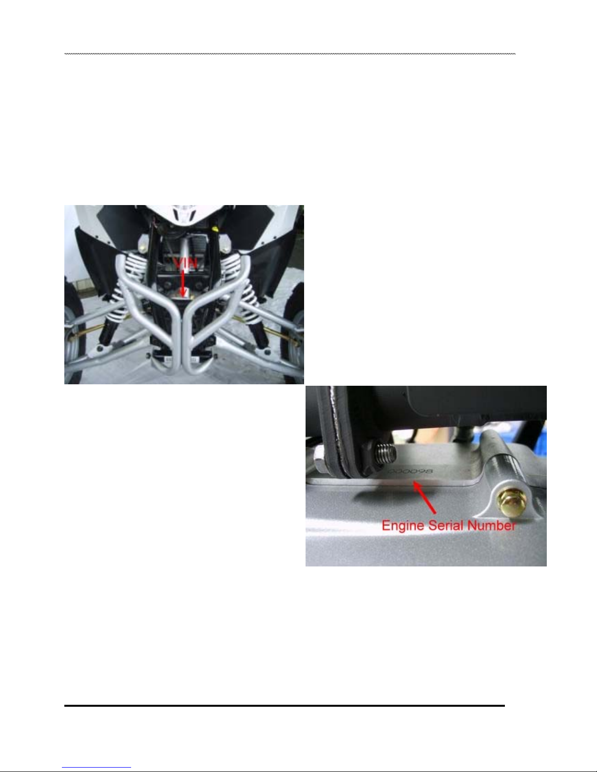
VIN Identification
Engine Serial Number Location
Whenever corresponding about an engine, be sure to refer to the
engine serial number. This information can be found stamped on
the top LH side of the crankcase as shown below.
Vehicle Identification Number Location
The vehicle identification number (VIN) and engine serial
number are important for identification purposes. See the
illustrations.
1.2
GENERALINFORMATION
8
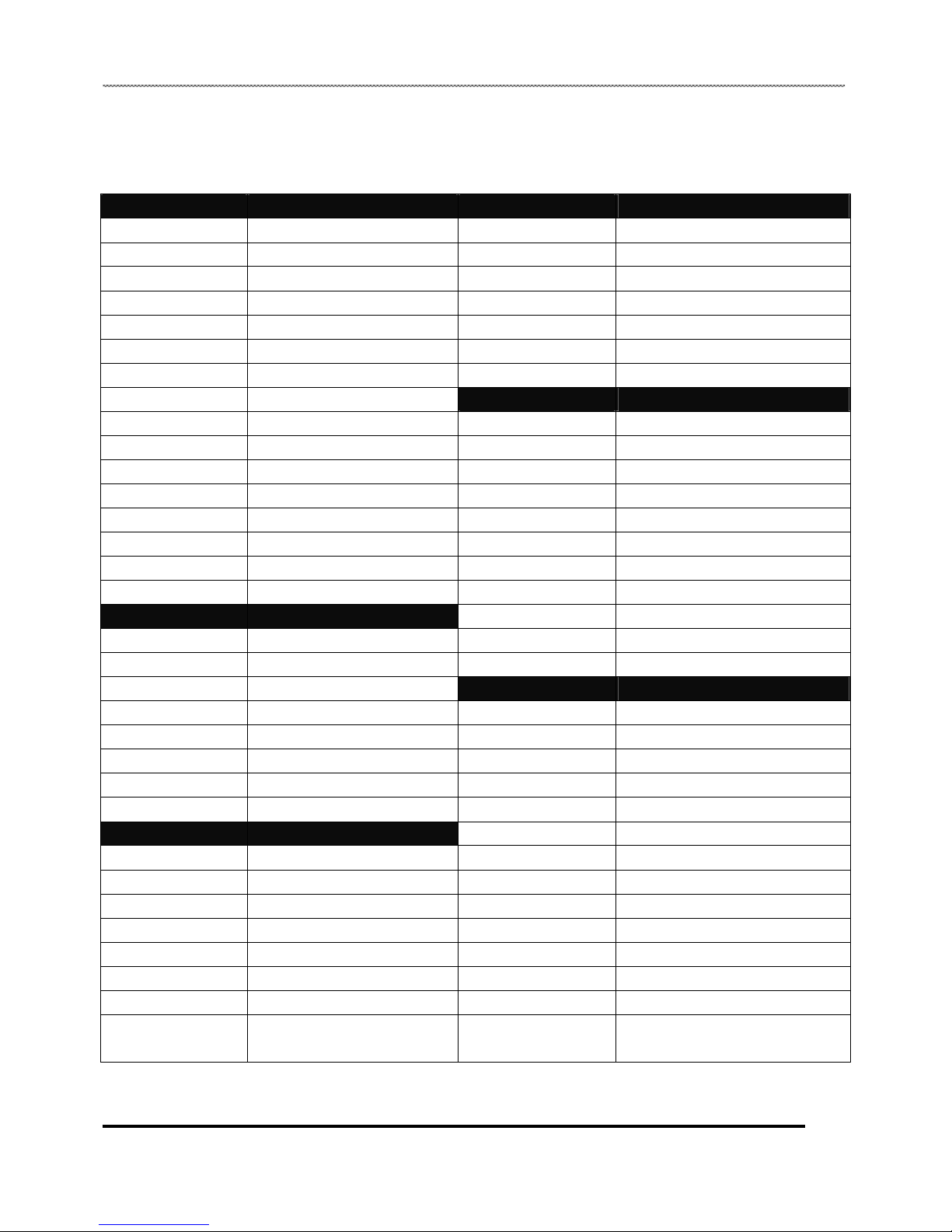
GENERAL SPECIFICATIONS
MODEL:GOES 300 S
ENGINE DRIVE SYSTEM
Type 4 Stroke, Simple overhead camshaft Oil capacity/ type 900 CC/ 80w90
Displacement 272.3 cc Transmission selection Forward, Neutral, Reverse
Cooling Water cooled Clutch type Centrifugal clutch
Bore and stroke 72.7mm×65.6mm Final drive Chain
Compression ratio 10.2 : 1 Forward gear ratio 17/45* 30/47
Number of valve 2 Rocker arm activated Reverse gear ratio 17/49* 21/37* 30/47
Inlet valve O30.5mm Rear Sprocket ratio 15/36
Inlet valve clearance 0.10mm CHASSIS
Exhaust valve O26.5mm Frame Steel
Exhaust valve clearance 0.10mm Front suspension Duel sock with double wishbone
Lubrication Wet sump and pump pressurized Front wheel travel 115 mm
Recommended oil 0W/ 50 Rear suspension Single shock with swing Arm
Oil capacity 1800 CC Rear wheel travel 165 mm
Starting system Electric start and coil start Front brake Duel disc with single bore caliper
Max. power 14kw/6500rpm Rear brake Single Disc with single bore caliper
Max. torque 22Nm/5500rpm Combined brake Foot pedal
CARBURATOR Parking device Cable controlled parking through rear caliper
Type Keihin /PTG/ ACV Front tire 21×7-10
Slide valve B34 Rear tire 20×10-9
Main jet 108 DIMENSIONS
Pilot jet 38S Overall length 1820 mm
Jet needle 2MKNN Overall width 1150 mm
Needle clip position notch 4th step from top Overall height 1160 mm
Air screw 1.0 circuit Seat height 790mm
Idle RPM 1400±100 Wheelbase 1300mm
ENG. ELECTRICAL Max. permissible weight 173Kg
Charging system Alternator and voltage regulator Number of seats 2
Alternator output 180W@6000RPM Min. ground clearance 170mm
Ignition type CDI Dry weight 205Kg
Spark plug type NGK/ DPR7EA-9 Front track 1125 mm
Spark plug gap 0.6~0.7mm Rear track 1125 mm
RPM limiter setting 8500 rpm Fuel tank capacity 8.5 Liter
Battery type GTX12-BS Max. speed 86 km/hr
Fuse type Charge 30A/ Main 15A/ Light 10A/ Spare
15A
1.3
GENERALINFORMATION
GENERAL VEHICLE INSPECTION
AND MAINTENANCE
Pre-Ride / Daily Inspection
Perform the following pre-ride inspection daily, and when
servicing the vehicle at each scheduled maintenance.
• Tires - check condition and tire pressure
• Fuel and oil - fill both to their proper level;
Do not overfill
• All brakes - check operation
• Throttle - check for free operation
• Headlight / Taillight / Brake light - check operation of all
indicator lights and switches
• Engine stop switch - check for proper function
• Wheels - check for loose wheel nuts
• Air cleaner element - check for dirt or water; clean or replace
• Steering - check for free operation, noting any unusual
looseness in any area
• Loose parts - visually inspect vehicle for any
damaged or loose nuts, bolts or fasteners
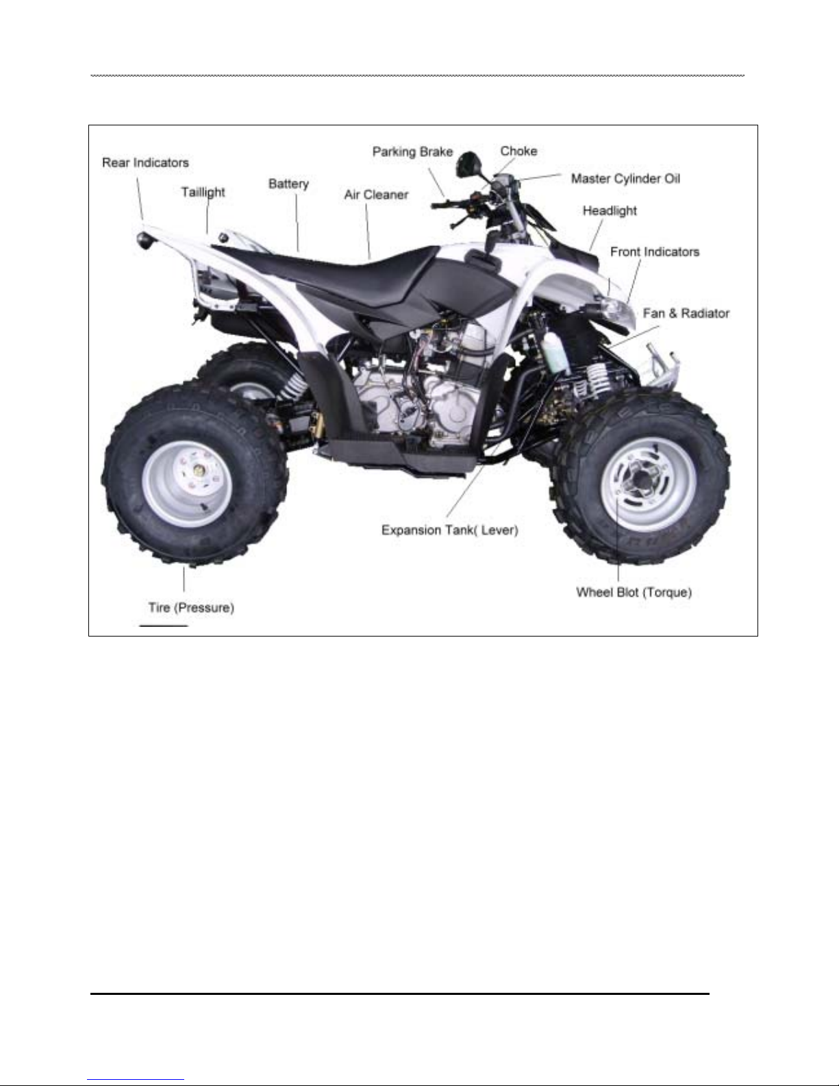
Vehicle Component Inspection Location
1.4

GENERALINFORMATION
GENERAL SPECIFICATIONS
MODEL:TREETRENTAR 330 ON ROAD
ENGINE DRIVE SYSTEM
Type 4 stroke simple overhead camshaft Oil capacity/ type 900 CC/ 80w90
Displacement 272.3 cc Transmission selection Forward, Neutral, Reverse
Cooling Water cooled Clutch type Centrifugal clutch
Bore and stroke 72.7mm×65.6mm Final drive Chain
Compression ratio 10.2 : 1 Forward gear ratio 17/45* 30/47
Number of valve 2 rocker arm activated Reverse gear ratio 17/49* 21/37* 30/47
Inlet valve O30.5mm Rear axle ratio 15/36
Inlet valve clearance 0.10mm CHASSIS
Exhaust valve O26.5mm Frame Steel
Exhaust valve clearance 0.10mm Front suspension Duel sock with double wishbone
Lubrication Wet sump lubrication and pump pressurized Front wheel travel 115 mm
Recommended oil 0W/ 50 Rear suspension Single shock with swing Arm
Oil capacity 1800 CC Rear wheel travel 165 mm
Starting system Electric start and coil start Front brake Duel disc with single bore caliper
Max. power 14kw/6500rpm Rear brake Single Disc with single bore caliper
Max. torque 22Nm/5500rpm Combined brake Foot pedal
CARBURATOR Parking device Cable controlled parking through rear caliper
Type Keihin /PTG/ ACV Front tire 21×7-10
Slide valve B34 Rear tire 20×10-9
Main jet 108 DIMENSIONS
Pilot jet 38S Overall length 1820 mm
Jet needle 2MKNN Overall width 1150 mm
Needle clip position notch 4th step from top Overall height 1160 mm
Air screw 1.0 circuit Seat height 790mm
Idle RPM 1400±100 Wheelbase 1300mm
ENG. ELECTRICAL Max. permissible weight 173Kg
Charging system Alternator and voltage regulator Number of seats 2
Alternator output 180W@6000RPM Min. ground clearance 170mm
Ignition type CDI Dry weight 205Kg
Spark plug type NGK/ DPR7EA-9 Front track 1125 mm
Spark plug gap 0.6~0.7mm Rear track 1125 mm
RPM limiter setting 8500 rpm Fuel tank capacity 8.5 Liter
Battery type GTX12-BS Max. speed 86 km/hr
Fuse type Charge 30A/ Main 15A/ Light 10A/ Spare
15A
1.5
GENERALINFORMATION
Vehicle Component Inspection Location
1.6

GENERALINFORMATION
Glossary Of Terms
ABDC: After bottom dead center.
ACV: Alternating current voltage.
Alternator: Electrical generator producing voltage alternating current.
ATDC: After top dead center.
BBDC: Before bottom dead center.
BDC: Bottom dead center.
BTDC: Before top dead center.
CC: Cubic centimeters.
Center Distance: Distance between center of crankshaft and center of driven clutch shaft.
Chain Pitch: Distance between chain link pins (No. 35 = 3/8" or 1 cm). Goes measures chain length in number of pitches.
CI: Cubic inches.
Clutch Buttons: Plastic bushings which aid rotation of the movable sheave in the drive and driven clutch.
Clutch Offset: Drive and driven clutches are offset so that drive belt will stay nearly straight as it moves along the clutch face.
Clutch Weights: Three levers in the drive clutch which relative to their weight, profile and engine RPM cause the drive clutch to close and
grip the drive belt.
Crankshaft Run-Out: Run-out or "bend" of crankshaft measured with a dial indicator while crankshaft is supported between centers on V
blocks or resting in crankcase. Measure at various points especially at PTO.
CVT: Centrifugal Variable Transmission (Drive Clutch System)
DCV: Direct current voltage.
Dial Bore Gauge: A cylinder measuring instrument which uses a dial indicator. Good for showing taper and out-of-round in the cylinder
bore.
Electrical Open: Open circuit. An electrical circuit which isn't complete.
Electrical Short: Short circuit. An electrical circuit which is completed before the current reaches the intended load. (i.e. a bare wire
touching the chassis).
End Seals: Rubber seals at each end of the crankshaft.
Engagement RPM: Engine RPM at which the drive clutch engages to make contact with the drive belt.
ft.: Foot/feet.
Foot Pound: Ft. lb. A force of one pound at the end of a lever one foot in length, applied in a rotational direction.
g: Gram. Unit of weight in the metric system.
gal.: Gallon.
ID: Inside diameter.
in.: Inch/inches.
Inch Pound: In. lb. 12 in. lbs. = 1 ft. lb.
kg/cm2: Kilograms per square centimeter.
kg-m: Kilogram meters.
Kilogram/meter: A force of one kilogram at the end of a lever one meter in length, applied in a rotational direction.
l or ltr: Liter.
lbs/in2: Pounds per square inch.
Left or Right Side: Always referred to based on normal operating position of the driver.
m: Meter/meters.
Mag: Magneto.
Magnetic Induction: As a conductor (coil) is moved through a magnetic field, a voltage will be generated in the windings. Mechanical
energy is converted to electrical energy in the stator.
mi.: Mile/miles.
mm: Millimeter. Unit of length in the metric system. 1 mm = approximately .040".
Nm: Newton meters.
1.7

GENERALINFORMATION
OD: Outside diameter.
Ohm: The unit of electrical resistance opposing current flow.
oz.: Ounce/ounces.
Piston Clearance: Total distance between piston and cylinder wall.
psi.: Pounds per square inch.
PTO: Power take off.
qt.: Quart/quarts.
Regulator: Voltage regulator. Regulates battery charging system output at approx. 14.5 DCV as engine RPM increases.
Reservoir Tank: The fill tank in the liquid cooling system.
Resistance: In the mechanical sense, friction or load. In the electrical sense, ohms, resulting in energy conversion to heat.
RPM: Revolutions per minute.
Seized Piston: Galling of the sides of a piston. Usually there is a transfer of aluminum from the piston onto the cylinder wall.
Possible causes: 1) improper lubrication; 2) excessive temperatures; 3) insufficient piston clearance; 4) stuck piston rings.
Stator Plate: The plate mounted under the flywheel supporting the battery charging coils.
TDC: Top dead center. Piston's most outward travel from crankshaft.
Volt: The unit of measure for electrical pressure of electromotive force. Measured by a voltmeter in parallel with the circuit.
Watt: Unit of electrical power. Watts = amperes x volts.
WOT: Wide open throttle.
1.8

MAINTENANCE
CHAPTER 2
MAINTENANCE
PERIODIC MAINTENANCE CHART. . . . . . . . . . . . .. . . . . . . . . . . . . . . . . . . . . . . . . . . . . 2.3
PERIODIC MAINTENANCE OVERVIEW. . . . . . . . . . . . . . . . . . . . . . . . . . . . . . . . . . . . . 2.3
PRE-RIDE - 40 HOUR MAINTENANCE INTERVAL . . . . . . . . . . . . . . . . . . . . . . . . . . . . 2.4
50 - 300 HOUR MAINTENANCE INTERVAL . . . . . . . . . . . . . . . . . . . . . . . . . . . . . . . . . . 2.5
GENERAL VEHICLE INSPECTION AND MAINTENANCE. . . . . . . . . . . . . . . . . . . . . . . . 2.6
FRAME, NUTS, BOLTS AND FASTENER INSPECTION . . . . . . . . . . . . . . . . . . . . . . . . 2.6
STANDARD TORQUE SPECIFICATIONS. . . . . . . . . . . . . . . . . . . . . . . . . . . . . . . . . . . . 2.6
STANDARD FASTENER TORQUES . . . . . . . . . . . . . . . . . . . . . . . . . . . . . . . . . . . . . . . 2.6
MAINTENANCE QUICK REFERENCE . . . . . . . . . . . . . . . . . . . . . . . . . . . . . . . . . . . . . . . 2.6
RE-COIL STRATER AND OPERATION . . . . . . . . . . . . . . . . . . . . . . . . . . . . . . . . . . . . . . .2.7
FUEL SYSTEM AND AIR INTAKE . . …. . . . . . . . . . . . . . . . . . . . . . . . . . . . . . . . . . . . . . . 2.7
FUEL SYSTEM SAFETY . . . . . . . . . . . . . . . . … . . . . . . . . . . . . . . . . . . . . . . . . . . . . . . . 2.7
THROTTLE STOP SPEED CONTROL SYSTEM. . . . . . . . . ... . . . . . . . . . . . . . . . . . . . . 2.7
CHOKE CABLE ADJUSTMENT. . . . . . . . . . . . . . . . . . . . . . . . . . . . ... . . . . . . . . . . . . . . 2.8
IDLE SPEED ADJUSTMENT . . . . . . . . . . . . . . . . .. . . . . . . . . . . . . . . . . . . . . . . . . . . . . 2.8
FUEL LINES . . . . . . . . . . . . . . . . . . . . . . . . . . . . . . . . . . . . . . . . . . . . . . . . . . . . . . . . . . 2.8
AIR SCREW ADJUSTMENT. . . . . . . . . . . . . . .. . . . . . . . . . . . . . . . . . . . . . . . . . . . . . . . 2.9
FUEL FILTER . . . . . . . . . . . . . . . . . . . . . . . . . . . . . . . . . . .. . . . . . . . . . . . . . . . . . . . . . . 2.9
FUEL VALVE LOCATION. . . . . . . . . . . . . . . . . . . . . . . . . . . . . . . . . . . . . . . . . . . . . . . . 2.10
CARBURETOR DRAINING . . . . . . . . . . . . . . . . . . . . . . . . . . . . . . . . . . . . . . . . . . . . . . 2.10
AIR FILTER SERVICE . . . . . . . . . . . . . . . . . . . . . . . . . . . . . . . . . . . . . . . . . . . . . . . . . . 2.11
ENGINE . . . . . . . . . . . . . . . . . . . . . . . . . . . . . . . . . . . . . . . . . . . . . . . . . . . . . . . . . . . . . . 2.12
ENGINE OIL LEVEL . . . . . . . . . . . . . . . . . . . . . . . . . . . . . . . . . . . . . . . . . . . . . . . . . . . . 2.12
ENGINE OIL AND FILTER CHANGE. . . . . . . . . . . . . . . . . . . . . . . . . . . . . . . . . . . . . . . 2.12
COMPRESSION/ LEAKDOWN TEST . . . . . . . . . . . . . . . . . . . . . . . . . . . . .. . . . . . . . . . 2.13
VALVE CLEARANCE ADJUSTMENT . . . . . . . . . . . . . . . . . . . . . . . . . . . . . . . . . . .. . . . 2.13
ENGINE MOUNTS . . . . . . . . . . . . . . . . . . . . . . . . . . . . . . . . . . . . . . . . . . . . . . . . . . . . . 2.14
ENGINE FASTENER TORQUE . . . . . . . . . . . . . . . . . . . . . . . . . . . . . . . . . . . . . . . . . . . 2.14
CVT DRYING. . . . . . . . . . . . . . . . . . . . . . . . . . . . . . . . . . . . . . . . . . . . . . . . . . . . . . . . . . 2.14
TRANSMISSION AND FINAL DRIVE . . . . . . . . . . . . . . . . . . . . . . . . . . . . . . . . . . . . . . . 2.14
TRANSMISSION LUBRICATION . . . . . . . . . . . . . . . . . . . . . . . . . . . . . . . . . . . . . . . . . . 2.14
TRANSMISSION LUBRICANT LEVEL. . . . . . . . . . . . . . . . . . . . . . . . . . . . . . . . . . . . . . 2.14
TRANSMISSION LUBRICANT CHANGE. . . . . . . . . . . . . . . . . . . . . . . . . . . . . . . . . . . . 2.14
DRIVE CHAIN INSPECTION -. . . . . . . . . . .. . . . . . . . . . . . . . . . . . . . . . . . . . . . . . . . . . 2.15
DRIVE CHAIN ADJUSTMENT - . . . . . . . . . . . . . . . . . . … . . . . . . . . . . . . . . . . . . . . . . . 2.15
2.1

MAINTENANCE
SPROCKET INSPECTION . . . . . . . . . . . . . . . . . . . . . . . . . . . . . . . . . . . . . . . . . . . . . . . 2.16
ELECTRICAL AND IGNITION SYSTEM . . . . . . . . . . . . . . . . . . . . . . . . . . . . . . . . . . . . . 2.16
BATTERY REMOVAL. . . . . . . ... . . . . . . . . . . . . . . . . . . . . . . . . . . . . . . . . . . . . . . . . . . 2.16
BATTERY CLEANING . . . . . . . . . . . . . . . . . . . . . . . . . . . . . . . . . . . . . . . . . . . . . . . . . . 2.17
BATTERY INSTALLATION. . . . . . . . . . . . . . . . . . . . . . . . . . . . . . . . . . . . . . . . . . . . . . . 2.17
BATTERY STORAGE. . . . . . . . . . . . . . . . . . . . . . . . . . . . . . . . . . . . . . . . . . . . . . . . . . . 2.17
BATTERY INSPECTION . . . . . . . . . . . . . . . . . . . . . . . . . . . . . . . . . . . . . . . . . . . . . . . . 2.17
FUSES / FUSE HOLDER LOCATION . . . . . . . . . . . . . . . . . . . . . . . . . . . . . . . . . . . . . . 2.18
SPARK PLUG INSPECTION . . . . . . . . . . . . . . . . . . . . . . . . . . . . . . . . . . . . . . . . . . . . . 2.18
ENGINE/ FRAME GROUND . . . . . . . . . . . . . . . . . . . . . . . . . . . . . . . . . . . . . . .. . . . . . . 2.18
STEERING AND SUSPENSION . . . . . . . . . . . . . . . . . . . . . . . . . . . . . . . . . . . . . . . . . . . 2.19
STEERING . . . . . . . . . . . . . . . . . . . . . . . . . . . . . . . . . . . . . . . . . . . . . . . . . . . . . . . . . . .2.19
TIE ROD END / STEERING INSPECTION . . . . . . . . . . . . . . . . . . . . . . . . . . . . . . . . . . 2.19
LUBRICATION/ GREASE POINTS . . . . . . . . . . . . . . . . . . . . . . . . . . . . . . . . . . . . . . . . 2.20
WHEEL ALIGNMENT. . . . . . . . . . . . . . . . . . . . . . . . . . . . . . . . . . . . . . . . . . . . . . . . . . . 2.20
WHEEL ALIGNMENT . . . . . . . . . . . . . . . . . . . . . . . . . . . . . . . . . . . . . . . . . . . .. . . . . . . 2.20
TOE ADJUSTMENT . . . . . . . . . . . . . . . . . . . . . . . . . . . . . . . . . . . . . . . . . . . . . . . . . . . . 2.21
FRONT SUSPENSION INSPECTION . . . . . . . . . . . . . . . . . . . . . . . . . . . . . . . . . . . . . . 2.21
REAR SUSPENSION INSPECTION . . . . . . . . . . . . . . . . . . . . . . . . . . . . . . . . . . . . . . . 2.22
SUSPENSION SPRING ADJUSTMENT . . . . . . . . . . . . . . . . . . . . . . . . . . . . . . . . . . . . 2.22
BRAKE SYSTEM. . . . . . . . . . . . . . . . . . . . . . . . . . . . . . . . . . . . . . . . . . . . . . . . . . . . . . . 2.22
BRAKE SYSTEM INSPECTION. . . . . . . . . . . . . . . . . . . . . . . . . . . . . . . . . . . . . . . . . . . 2.22
BRAKE LEVER TRAVEL . . . . . . . . . . . . . . . . . . . . . . . . . . . . . . . . . . . . . . . . . . . . . . . . 2.22
PARKING BRAKE ADJUSTMENT. . . . . . . . . . . . . . . . . . . . . . . . . . . . . . . . . . . . . . . . . 2.23
WHEELS AND TIRES . . . . . . . . . . . . . . . . . . . . . . . . . . . . . . . . . . . . . . . . . . . . . . . . . . . 2.23
WHEELS. . . . . . . . . . . . . . . . . . . . . . . . . . . . . . . . . . . . . . . . . . . . . . . . . . . . . . . . . . . . . 2.23
WHEEL, HUB AND SPINDLE TORQUE TABLE . . . . . . . . . . . . . . . . . . . . . . . . . . . . . . 2.23
WHEEL INSPECTION . . . . . . . . . . . . . . . . . . . . . . . . . . . . . . . . . . . . . . . . . . . . . . . . . . 2.23
WHEEL REMOVAL - FRONT / REAR . . . . . . . . . . . . . . . . . . . . . . . . . . . . . . . . . . . . . . 2.23
WHEEL INSTALLATION - FRONT / REAR . . . . . . . . . . . . . . . . . . . . . . . . . . . . . . . . . . 2.24
TIRE PRESSURE. . . . . . . . . . . . . . . . . . . . . . . . . . . . . . . . . . . . . . . . . . . . . . . . . . . . . . 2.24
TIRE INSPECTION. . . . . . . . . . . . . . . . . . . . . . . . . . . . . . . . . . . . . . . . . . . . . . . . . . . . . 2.24
2.2

MAINTENANCE
PERIODIC MAINTENANCE CHART
Periodic Maintenance Overview
Careful periodic maintenance will help keep your vehicle in the safest, most reliable condition. Inspection,
adjustment and lubrication of important components are explained in the periodic maintenance chart.
Inspect, clean, lubricate, adjust and replace parts as necessary. When inspection reveals the need for replacement
parts, use genuine Goes parts available from your dealer.
NOTE: Service and adjustments are critical. If you’re not familiar with safe service and adjustment procedures, have
qualified dealer perform these operations.
Maintenance intervals in the following chart are based upon average riding conditions and an average vehicle speed
of approximately 10 miles per hour. Vehicles subjected to severe use must be inspected and serviced more
frequently.
Severe Use Definition
• Frequent immersion in mud, water or sand
• Racing or race-style high RPM use
• Prolonged low speed, heavy load operation
• Extended idle
• Short trip cold weather operation
Pay special attention to the oil level. A rise in oil level during cold weather can indicate contaminants collecting in oil
sump or crankcase. Change oil immediately if the oil level begins to rise. Monitor the oil level, and if it continues rise,
discontinue use and determine the cause or see your dealer.
Maintenance Chart Key
The following symbols denote potential items to be aware of during maintenance:
■ = CAUTION: Due to the nature of these adjustments, it is recommended this service be performed by
authorized GOES dealer.
◆ = SEVERE USE ITEM -- See Above
NOTE: Inspection may reveal the need for replacement parts. Always use genuine Goes parts.
Improperly performing the procedures marked with a■
could result in component failure and lead to serious injury
or death. Have an authorized GOES dealer perform these
services.
2.3
MAINTENANCE
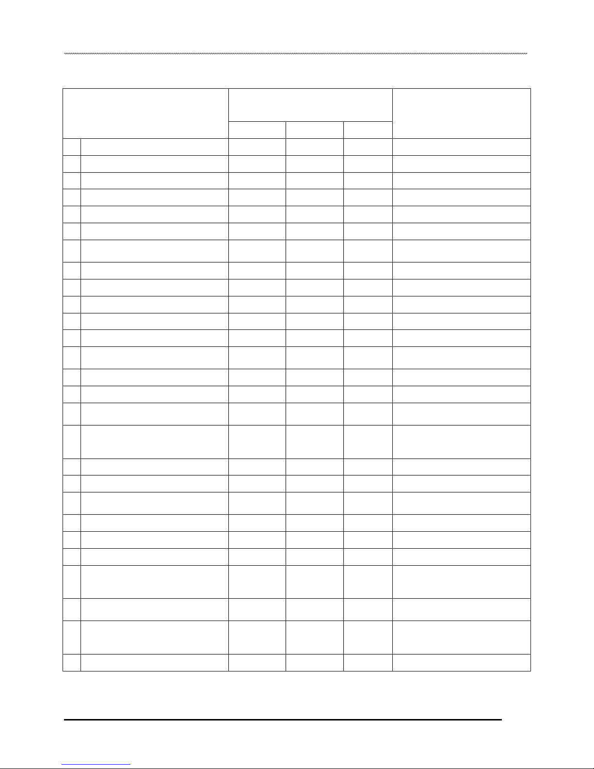
Pre-Ride - 40 Hour Maintenance Interval
Periodic Maintenance Chart
Maintenance Interval
(whichever comes first)
ITEM
Hours Calendar KM
Remarks
■Steering - Pre-Ride - Check for free operation
◆ Front- Suspension - Pre-Ride - Make adjustments as needed.
◆ Rear- Suspension - Pre-Ride - Make adjustments as needed.
Tire - Pre-Ride -
Make adjustments as needed.
Brake system - Pre-Ride - Check Operation
Auxiliary brake - Pre-Ride - Inspect daily; adjust as needed.
Drive chain - Pre-Ride - Check condition and slack; refer
to “drive chain adjustment”
Brake light - Pre-Ride - Check for proper operation.
Throttle - Pre-Ride - Check Operation
Wheels/ Fasteners - Pre-Ride - Make adjustments as needed.
Frame fasteners - Pre-Ride - Make adjustments as needed.
◆ Engine oil lever - Pre-Ride - Make adjustments as needed.
Air filter - Pre-Ride - Inspect; clean often, replace as
needed.
■ Extension tank coolant - Pre-Ride - Inspect coolant lever.
◆ Air box sediment tube Daily Drain deposits when visible.
Head lamp/ tail lamp Daily Check operation; apply dielectric
grease if replacing.
CVT housing Weekly Drain water as needed, check
often if operating in wet
conditions.
■ Brake lever travel 10H Monthly 150 Inspect regularly.
◆ Brake freeplay 10H Monthly 150 Inspect regularly.
■ Spark plug 10H Monthly 150 Clean; check condition; adjust
gap; replace as needed.
Idle speed 10H Monthly 150 Check; adjust as needed.
■ Choke 10H Monthly 150 Check for proper operation.
Battery 20H Monthly 300 Check terminals; clean; test.
■
◆
Engine oil change * Severe duty
**Normal Duty
30H
50h
6M
12M
500
1000
Perform a break-in oil change at
20 hours, change more frequently
during cold weather
■ Radiator 40H 12M 650
inspect external surface; change
coolant
◆ Transmission oil change 40H 12M 650 Inspect level; change yearly;
perform break-in oil change after
the first 10 hours of operation.
◆ Oil pre-filter screen 40H 12M 650 Clean filter at every oil change;
■ Perform these procedures more often for vehicles subjected to severe use.
◆ Have an authorized GOES dealer perform these services.
2.4
MAINTENANCE
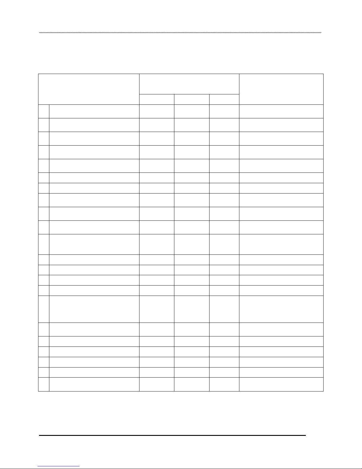
50 - 300 Hour Maintenance Interval
Periodic Maintenance Chart
Maintenance Interval
(whichever comes first)
ITEM
Hours Calendar KM
Remarks
◆General lubrication 50H 3M 800
Lubricate all grease fittings,
pivots, & cables.
■ Carburetor float bowl 50H 6M 800
Drain bowl periodically and prior
to storage.
■ Throttle cable 50H 6M 800
Inspect; adjust; lubricate; replace
if necessary.
■ Choke cable 50H 6M 800
Inspect; adjust; lubricate; replace
if necessary.
◆ Carburetor intake flange 50H 6M 800
Inspect for proper sealing / air
leaks.
■ Brake pads wear 50H 6M 800 Inspect; replace as needed.
■ Drive belt 50H 6M 800 Inspect; replace as needed.
Shift linkage & cable 50H 6M 800
Inspect; adjust; lubricate; replace
if necessary.
◆ Front suspension 50H 6M 800
Inspect; lubricate; tighten
fasteners.
◆ Rear suspension 50H 6M 800
Inspect; lubricate; tighten
fasteners.
■ Fuel system 100H 12M 1500
Check for leaks at tank cap, lines,
fuel valve, filter, carburetor,
replace lines every two years.
■ Fuel filter 100H 12M 1500 Replace yearly.
◆ Engine mounts 100H 12M 1500 Inspect.
◆ Exhaust muffler/ pipe 100H 12M 1500 Inspect.
■ Ignition timing 100H 12M 1500 Inspect.
◆ Wring 100H 12M 1500
Inspect for wear, routing,
security; apply dielectric grease
to connectors subjected to water,
mud, etc.
■ Clutch ( drive & driven ) 100H 12M 1500
Inspect; clean; replace worn
parts.
■ Front wheel bearings 100H 12M 1500 Inspect; replace as needed.
◆ Valve clearance 100H 12M 1500 Inspect; adjust.
◆ Ignition timing 100H 12M 1500 Inspect
◆ Brake fluid 100H 12M 1500 Change every two years.
■ Toe adjustment - - -
Inspect periodically; adjust when
parts are replaced.
■ Perform these procedures more often for vehicles subjected to severe use.
◆ Have an authorized Goes dealer perform these services.
2.5

MAINTENANCE
GENERAL VEHICLE INSPECTION AND MAINTENANCE
Frame, Nuts, Bolts and Fastener Inspection
Periodically inspect the torque of all fasteners in accordance with the maintenance schedule. Check that all cotter pins are in
place. Refer to specific fastener torques listed in each chapter.
Standard Torque Specifications
The following torque specifications are to be used as a general guideline. There are exceptions in the steering, suspension, and
engine areas. Always consult the exploded views in each manual section when available for torque values of fasteners before
using standard torque.
Standard Fastener Torques
Thread Size TORQUE (ft. lbs. / in. lbs.) TORQUE (Nm)
5 mm bolts and nuts 39-52 in. lbs. 4.5-6 Nm
6 mm bolt and nuts 69-104 in. lbs. 8-12 Nm
8 mm boltsand nuts 13-18 ft. lbs. 18-25 Nm
10 mm bolts and nuts 22-29 ft. lbs. 30-40 Nm
12 mm bolts and nuts 36-43 ft. lbs. 50-60 Nm
4 mm screws 22-30 in. lbs. 2.5-3.4 Nm
5 mm screws 30-43 in. lbs. 3.5-5 Nm
6 mm Hex bolts 87-121 in. lbs. 10-14 Nm
8 mm Hex bolts 17-22 ft. lbs. 24-30 Nm
10 mm Hex bolts 25-32 ft. lbs. 35-45 Nm
Maintenance Quick Reference
Item Lube Rec. Method Frequency
1 Engine oil OW-50 Synthetic Check level or
change oil Check during pre-ride inspection change
oil every 30 hours or 6 months.
2 Transmission SAE80W-90 Gear Lubricant Check level or
change lube. Inspect periodically and change
lubrication every 40 hours or annually.
3 Brake fluid DOT-4 Brake Fluid Fill master cylinder
reservoir to indicated
lever inside reservoir.
As require. Change fluid every 2 years.
4 Drive Chain Chain Lube or SAE
80W/90 Lubricate drive chain
Lubricate as required and before
each ride in wet conditions.
More often in severe use.
5 Front Suspension
A-Arm and Spindle) Premium All Season
Grease Inspect; tighten
fasteners; grease
zerks
Every 3 months or 50 hours (also after
washing ATV or driving in water). More
often in severe use
2.6
MAINTENANCE
Re-Coil Starter and Operation
If the battery becomes too weak to start the engine, use the
re-coil starter to start the engine until the battery is serviced.
1. Position the vehicle on a level surface.
2. Shift the transmission into neutral (if equipped).
3. Lock the parking brake.
4. Push the engine stop switch up to the RUN position.
5. Turn the key ON.
6. Pull the re-coil to crank the engine.
Always stop the engine and refuel outdoors or in a well
ventilated area.
Do not smoke or allow open flames or sparks in or near
the area where refueling is performed or where gasoline
is stored.
Do not overfill the tank.
Fill the tank to the bottom of the filler neck.
This will allow for thermal expansion.
If you get gasoline in your eyes or swallow gasoline, see
your doctor immediately.
If you spill gasoline on your skin or clothing, immediately
wash it off with soap and water and change clothing.
Never start the engine or run it in an enclosed area.
Gasoline powered engine exhaust fumes are poisonous
and can cause loss of consciousness and death in a
short time.
FUEL SYSTEM AND AIR INTAKE
Fuel System Safety
Gasoline is extremely flammable and explosive under
certain conditions.
Throttle Stop Speed Control System
IMPORTANT: This procedure should be performed
by consumers only when they determine that their
child is capable of handling the additional speed.
2.7
MAINTENANC
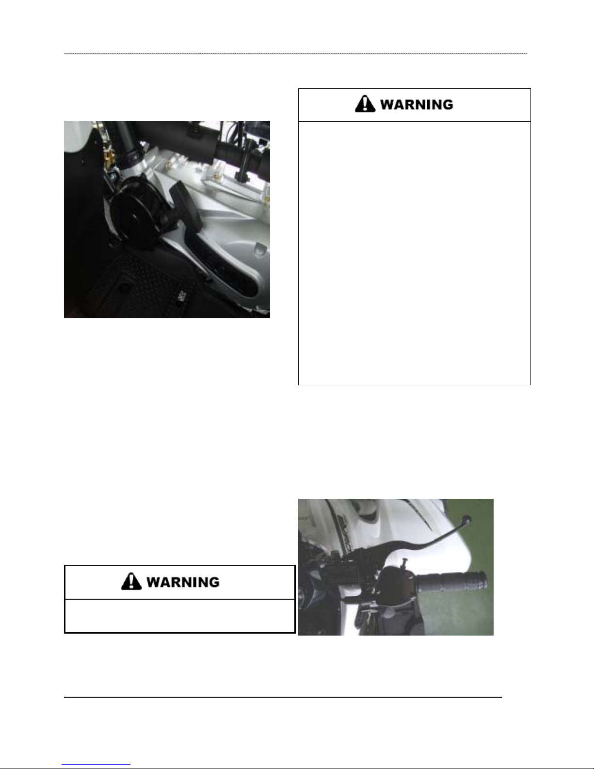
Choke Cable Adjustment
Verify free play of 1.6-4.76 mm (1/16-3/16”) and smooth
operation of choke cable.
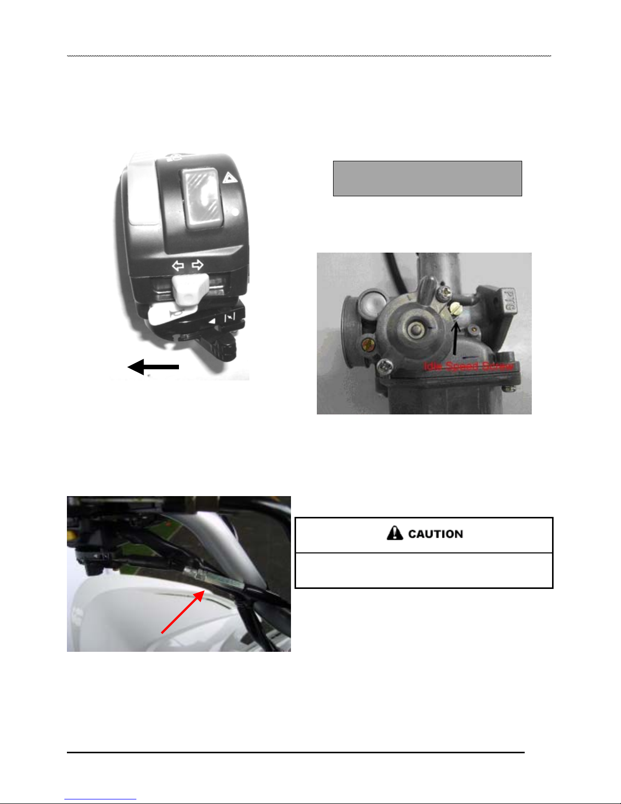
Idle Speed Adjustment
1. Start engine and warm it up thoroughly.
2. Adjust idle speed by turning the slide adjustment screw in
(clockwise) to increase or out (counterclockwise) to decrease RPM.
(Refer to illustration).
Idle Speed
1400 ± 100 r.p.m.
NOTE: Adjusting the idle speed affects throttle
cable freeplay. Always check throttle cable freeplay
after adjusting idle speed and adjust if necessary.
Adjustments to the freeplay can be made by loosening the
choke cable adjustment in or out to gain the desired
freeplay.
If smooth choke operation is not obtainable, inspect choke
cable for kinks or sharp bends in routing.
Fuel Lines
1. Check fuel lines for signs of wear, deterioration, damage, or
leakage. Replace if necessary.
2. Be sure fuel lines are routed properly and secured with cable
ties.
Make sure all fuel lines and vent lines are not kinked or
pinched.
3. Replace all fuel lines every two years.
2.8

MAINTENANCE
Air Screw Adjustment
1. Set idle speed to specification. Always check throttle cable
freeplay after adjusting idle speed and adjust if necessary.
2. To adjust the mixture screw setting, you will need to use
the Adjustment Screwdriver. Slowly turn the mixture screw
clockwise until engine idle RPM begins to decrease. Stop turning
at this point.
3. Slowly turn mixture screw counterclockwise until idle speed
returns to maximum RPM. Continue turning counterclockwise
until idle RPM begins to drop. Stop turning at this point.
4. Center the mixture screw between points in Step 2 and 3.
5. Readjust idle speed if not within specification.
Fuel Filter
The fuel filter should be replaced in accordance with the
“Periodic Maintenance Chart” or whenever sediment is
visible
in the filter.
Fuel Filter Location - Located in-line between fuel valve
and carburetor inlet.
To service the fuel filter:
1. Shut off fuel supply at fuel valve.
2. Remove line clamps at both ends of the filter.
3. Remove fuel lines from filter.
4. Install new filter and clamps onto fuel lines.
5. Turn fuel valve to ‘ON’.
6. Start engine and inspect for leaks.
Pilot Air Screw Base Setting:
Keihin: 1.0 turns out
2.9
Air Screw
This manual suits for next models
2
Table of contents
Popular Offroad Vehicle manuals by other brands


Yamaha
Yamaha YFM250XN 2001 Supplementary service manual

Cobra
Cobra 2008 ECX70 Service manual

High Lifter
High Lifter Arctic Cat Wild Cat Lower Radius Bars quick start guide

Yamaha
Yamaha RAPTOR YFM660RR owner's manual

Can-Am
Can-Am 2009 Outlander 500 EFI Operator's guide

BOMBARDIER
BOMBARDIER SKI-DOO MX-Z Renegade 600 HO SDI Operator's guide