Boozhound Laboratories JFET User manual

Boozhound Laboratories JFET Phono Preamp
Assembly manual (rev.2)
The Boozhoundlabs Philosophy
The plan here is to offer kits that let the curious audiophile experience designs that they would otherwise have to build
from scratch. The parts used in this kit are for the most part considered obsolete and are probably no longer being
manufactured. I source this stuff from overseas via eBay.
I think simplicity is a huge part of why classic equipment sounds so good, and modern stuff can sound so bad. In the days
when capacitors and transformers were expensive, designers minimized the parts count in any design, and this approach
is audible even when designing with modern devices. And for those of us who not only want to build stuff, but to
understand how it works, simple designs are much more comprehensible, with no "black boxes" that we only
understand through the abstraction of a spec sheet.
Why not have fun building stuff instead of just pouring dollars into your system on the quest for ultimate-ness? Part of
the fun for me is the ability to try something new without having to shell out the big bucks.
The JFET Phono Preamp
This is just about the simplest circuit possible that will accomplish what we need - reverse-RIAA equalization with gain.
This is 2 JFET gain stages with a passive (no feedback) RIAA equalization network sandwiched between them.
For more info, and to see how other builders have done something similar, you can search for a circuit called “Le Pacific”
which is the same topology, but with a slightly different EQ section and parts values.
Pretty nifty, huh? Only 22 parts per channel including the power supply filter stuff. The JFET gain stages are straight from
any electronics textbook. The RIAA filter section made up of R5, R8, C1, C2, and C3 are calculated using standard
formulas. Nothing special here –except that almost nobody does it like this.
Gain is approximately 40dB (about 30dB per gain stage, minus about 20dB for the RIAA EQ).

Inventory
Start by verifying that you have all of the parts you need. I endeavor to make sure I send only complete kits, but it is
always possible I missed something. If I screwed up and left something out, please email me immediately at
jsn@boozhoundlabs.com and I will make it right.
Here is what is included with each kit, with checkboxes to make it easy to verify that you have all of this stuff:
( ) 1 Printed Circuit Board
( ) 4 2sk170 transistors
( ) 4 220uF electrolytic capacitor Nichicon Muse
( ) 4 0.1uF PIO capacitor Russian K40-Y
( ) 2 0.033uF PIO capacitor Russian K40-Y
( ) 2 0.001uF PIO capacitor Russian K40-Y
( ) 2 1uF PIO capacitor Russian K42-Y
( ) 4 10 ohm resistor Brown, black, black, gold, brown
( ) 4 49.9 ohm resistor Yellow, white, white, gold, brown
( ) 4 100 ohm resistor Brown, black, black, black, brown
( ) 6 3.16k resistor Orange, brown, blue, brown, brown
( ) 2 28k resistor Red, gray, black, red, brown
( ) 2 47k resistor Yellow, violet, black, red, brown
( ) 2 100k resistor Brown, black, black, orange, brown
( ) 2 1M resistor Brown, black, black, yellow, brown

Assembly
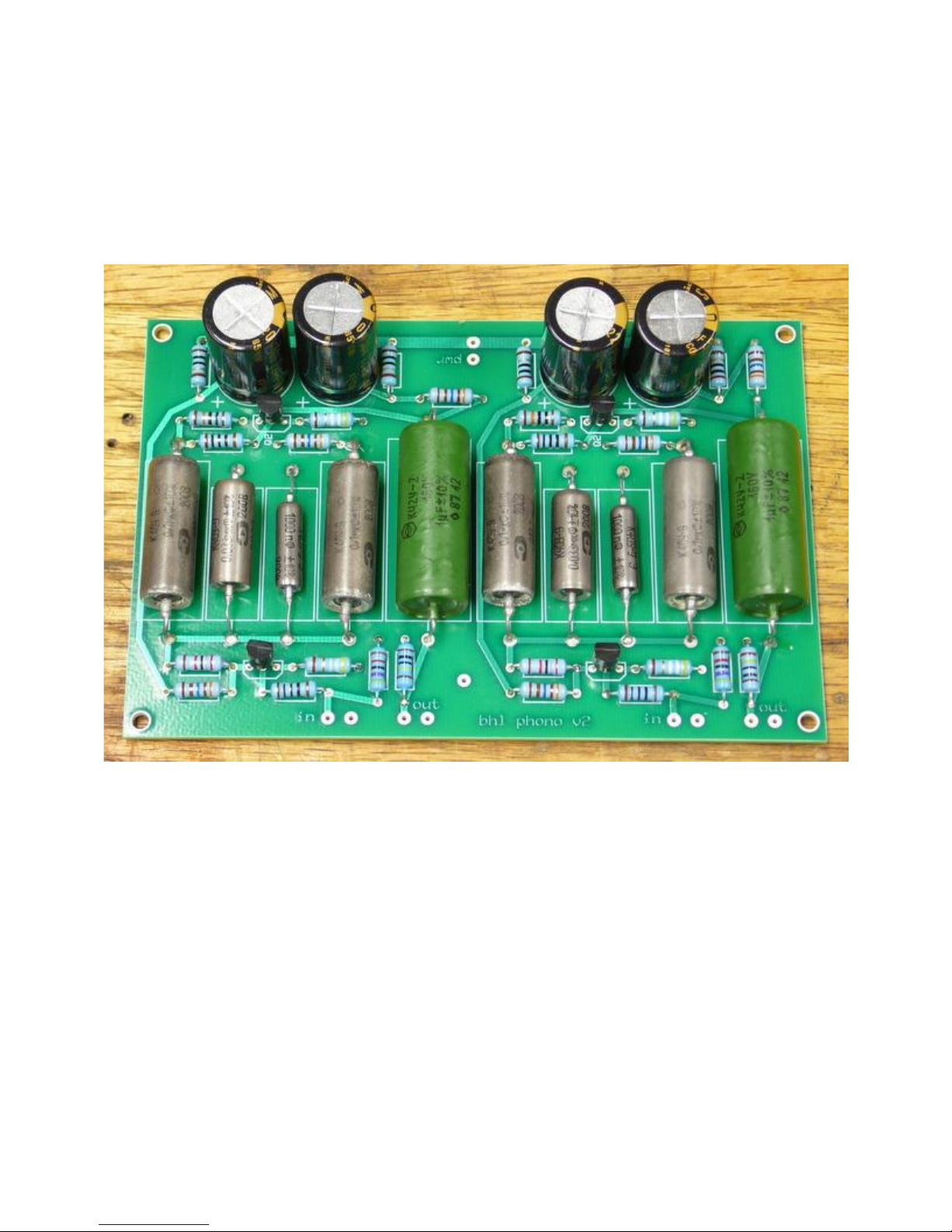
This is almost self-explanatory, but I will offer a few tips, and a few photos.
It is generally a good idea to install the little stuff first and the big stuff afterwards, so that you aren’t melting the big
stuff trying to get to the little stuff. Start with the resistors and the JFETs.
There will be 2 matched pairs of JFETs. Use each pair in the same position in both channels –one pair will be Q1 in both
channels, the other Q2. This will maintain the same amount of gain on both channels. It doesn’t matter which pair is Q1
and which is Q2.
I like to solder from the bottom of the board because it is easier to get to things, and the odds of overheating a part are
lower because you are that much further from the part itself. Be sure to heat the pad and the leads sufficiently to let the
solder flow all the way to the top of the board though. These boards have through-plated holes, so it will be easy.
These boards have traces only on one side, leaving the bottom side to be nothing but a huge ground plane. This will
reduce grounding problems and make this a very quiet design.
I also made the gap between the ground plane and the pads really huge so that it would be hard to accidentally ground
out a component. I tend to use a soldering iron tip until it is far from pointy, so the spacing helps me keep everything
tidy.
The points where the components do attach to the ground plane will take a bit more heat to solder properly since the
ground plane will act as a heat sink.
Next install the capacitors. Or instead of “next” I should say “last” because you are done!
The only thing left to do is visually inspect the solder joints to make sure everything looks good and there are no solder
bridges or obvious cold solder joints.
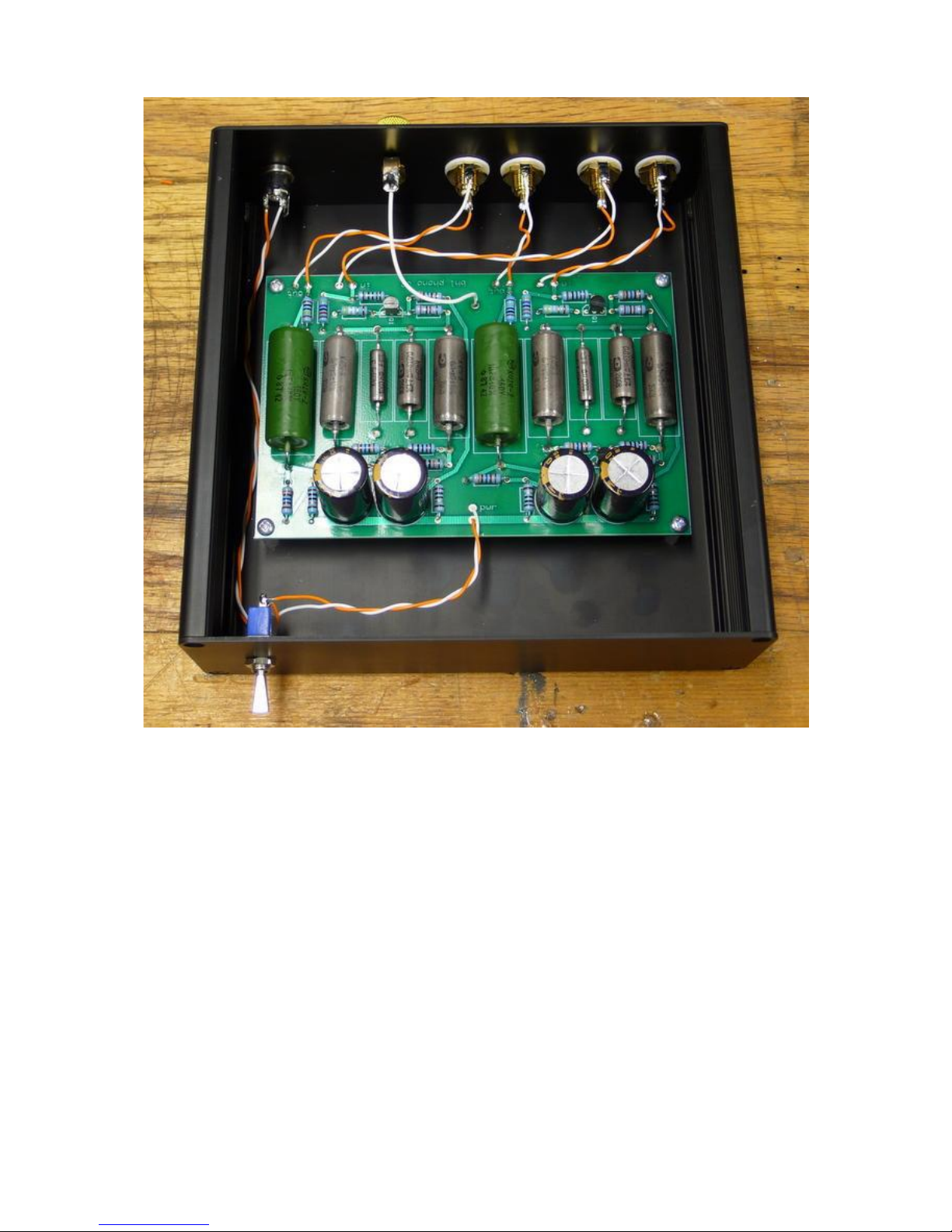
Integration
Connecting this to the various inputs and outputs is also super easy. The in and out pads are obvious. There is one more
pad I probably should have labeled “gnd” that is for a wire to connect to the chassis, ideally at a ground lug where you
connect the ground wire from your turntable.
The pwr pads need to be connected to a source of roughly 24 volts filtered DC. There is a bit of filtering (more like
decoupling) on the board, but not enough to filter AC. I use a mid-grade switch mode wall wart power supply for this
because they are cheap, easy, and very quiet. An upgraded regulated power supply would be a nice upgrade I’m sure.
There is no onboard fuse. The wall wart power supplies I imagine almost everyone will be using for this are internally
current limited. If you use another power supply, a fuse might be a good idea. Current draw is less than 50 mA.
I include the standard 47k load resistor, but feel free to change that to something that is better matched to your
cartridge or stepup transformer or whatever.
The mounting holes at the corners are designed for 4-40 thread screws. The boards measure 5.3”by 3.5”by 1.25”
assembled
Now go play a couple of those Steely Dan albums you buy every time you see them in the thrift store!
-jsn
Table of contents
Popular Amplifier manuals by other brands

Cicognani
Cicognani 6v6 Amp JAZZ & BLUES operating manual

Balanced Audio Technology
Balanced Audio Technology VK-500 owner's manual

Rotel
Rotel QA-101 Instruction/technical manual

DX Connection
DX Connection QSK 2500 instruction manual

Marshall Amplification
Marshall Amplification MG10 owner's manual

Amphenol Procom
Amphenol Procom PRO-ARU4G user manual


