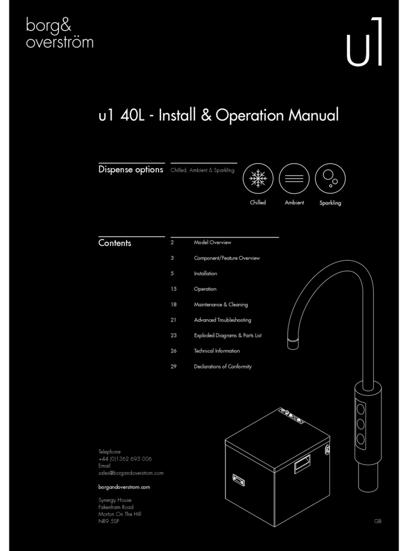
Borg & Overstrom u1 Instruction sheet

Install & Operation Guide
GB
ambient sparklingchilled
Dispense options
Contents
Chilled & Ambient
Chilled, Ambient & Sparkling
5 Range Overview & Features
7 Controls
8 Leak Detection
11 Installation & Operation -
u1 Chilled & Ambient
12 Major Components
17 Water Connection
21 Installation & Operation -
u1 Chilled, Ambient & Sparkling
22 Major Components
27 Water Connection
28 CO2 Bottle Installation & Sparkling
Water Operation
33 Sanitisation Guides
37 Trouble Shooting
45 Electrical Measurements, Component
Diagrams & Lists
56 Electrical Circuit & Water Pathway
Diagrams
62 Certicat
Telephone
+44 (0)1362 695 006
Email
sales@borgandoverstrom.com
borgandoverstrom.com
Synergy House
Fakenham Road
Morton On The Hill
NR9 5SP

The manual is intended as a guide only.
Printed by Borg & Overström NR9 5SP UK.
© Copyright Borg & Overström

u1 Undercounter Systems Install & Operation Guide | 3
GB
Contents
5Range Overview & Features
6 Introduction
7 Controls
8 Leak Detection
9 Specification
11 Installation & Operation - u1 Chilled & Ambient
12 Major Components
14 Positioning
17 Water Connection
18 Maintenance & Removal
19 General Safety Advice
21 Installation & Operation - u1 Chilled, Ambient & Sparkling
22 Major Components
24 Positioning
27 Water Connection
28 CO2 Bottle Installation & Sparkling Water Operation
29 Maintenance and Removal
30 Emptying the Carbonation Tank
31 General Safety Advice
33 Sanitisation Guides
34 u1 Sanitisation Guide
37 Trouble Shooting
38 Fault Diagnosis Guide 1 & 2 – No Water Dispenses
40 Fault Diagnosis Guide 3 – Water Dispenses but not correct Temperature
41 Fault Diagnosis Guide 4 – Water Leaks
42 Fault Diagnosis Guide 5 & 6 – Miscellaneous
45 Electrical Measurements, Component Diagrams & Lists
46 Electrical Test Measurement Values Guide
47 Exploded Component Diagram u1 Chilled & Ambient
48 Electrical Wiring Loom Diagram u1 Chilled & Ambient
49 u1 Chilled & Ambient – Parts List
52 Exploded Component Diagram u1 Chilled, Ambient & Sparkling
53 Electrical Wiring Loom Diagram u1 Chilled, Ambient & Sparkling
54 u1 Chilled, Ambient & Sparkling – Parts List
56 Electrical Circuit & Water Pathway Diagrams
57 Electrical Circuit Diagram u1 Chilled & Ambient
58 Electrical Circuit Diagram u1 Chilled & Ambient
59 Water Pathway Diagram u1 Chilled & Ambient
60 Water Pathway Diagram u1 Chilled & Ambient
62 Certificate

4 | u1 Undercounter Systems Install & Operation Guide
GB

u1 Undercounter Systems Install & Operation Guide | 5
GB
Contents
6 Introduction
7 Controls
8 Leak Detection
9 Specification
Range Overview & Features
u1 Undercounter system
All Models

6 | u1 Undercounter Systems Install & Operation Guide
GB
Range Overview & Features
Introduction
u1 is a range of undercounter water dispensers that are connected to the mains water supply and
dispense water through a proprietary swan-neck faucet that is mounted on a work surface.
There are two models in the range:
• u1 Chilled and Ambient
• u1 Chilled, Sparkling and Ambient
All Types
Both models have robust steel framed cabinets
and attractively injection moulded plastic front,
side and top panels.
An IEC Power Lead is supplied for connection
to the IEC socket found on the rear of all models
(An additional Schuko type is supplied for the
European market).
Both are Direct Chill cold water dispenser
where water is used as the cooling medium
in the Direct Chill tank. This is automatically
filled and controlled by the level control system
upon installation. This tank is then chilled via the
outer evaporation coil of the capillary controlled
refrigeration compression system. We recommend
fitting a Pressure Reducing Valve is fitted to all
supplies to regulate the pressure
to 3.5 bar/355 kPa.
u1 Chilled, Sparkling and Ambient
Models
On the carbonated water model, water is chilled
as it passes through the coil immediately before
dispense or being pumped under pressure into the
carbonator which it fitted inside the same coil.
The carbonator is also level controlled and allows
the sparkling effect to occur through saturation
with CO2.
Dispense is at inlet pressure and controlled via
the solenoid valves.
The Cold Temperature is thermostatically
controlled via the adjustment screw on the back
of the machine. This setting is factory set and
is not necessary to adjust in most cases
The Cold Tank can be drained via the two
Drain Port on the rear of the machine.
The level control system also incorporates a leak
detection device within the cabinet which switches
the machine off in the event of detecting water.

u1 Undercounter Systems Install & Operation Guide | 7
GB
Controls
Chilled & Ambient Models
Undercounter Unit
On/Off switch
At upper rear of machine.
Switches Cooling Operation on/off.
Cold Thermostat
At rear of machine.
10A Fuse
On rear of machine, integral with IEC socket
Top LED
Colours to show Power is switched on
Middle LED
Colours to show Cooling Mode is switched on
Bottom LED
Colours to show when compressor is operating/
water is above set point
Control Button Panel
Ambient Button (Top)
Press to dispense ambient water
Cold Button (Bottom)
Press to dispense Cold water
Chilled & Sparkling Models
Undercounter Unit
On/Off switch
At upper rear of machine.
Switches Cooling Operation on/off.
Soda switch
Switches Sparkling Operation on/off.
Cold Thermostat
At rear of machine.
10A Fuse
On rear of machine, integral with IEC socket
Top LED
Colours to show the Sparkling Operation is
switched on
Middle LED
Colours to show Cooling Mode is switched on
Bottom LED
Colours to show when compressor is operating/
water is above set point
Control Button Panel
Ambient Button (Top)
Press to dispense ambient water
Sparkling Button (Middle)
Press to dispense Sparkling Water
Cold Button (Bottom)
Press to dispense Cold Water
Factory set to:
Cold Thermostat
NB: Turn clockwise to decrease water temperature
DURING NORMAL OPERATION THE ONLY LED INDICATORS
ARE THOSE ON THE FRONT PANEL OF THE UNDERCOUNTER UNIT
-C
+C

8 | u1 Undercounter Systems Install & Operation Guide
GB
Leak Detection
Notice:
This machine is equipped with a leakage detection device.
When leaking is detected, the dispense operation will be cut
off automatically.
This is indicated by the alarm signalling as also described above.
To reset:
Locate the source of leakage and rectify. Locate the detection probe which can
be found in the bottom front left hand
corner. Dry the probes and internal area
with a dry cloth.
Unplug the machine and remove the left
side plate.
Locate the Leak Detector valve. Reset the red lever (push it in). Reconnect the power to machine
and test operation.
HOT
1 2
4
3
5 6

u1 Undercounter Systems Install & Operation Guide | 9
GB
Specification
COOLING SYSTEM u1
All Systems
High efficiency compression system with capillary
control. Premium quality long life hermetic
compressor. Compact internal condenser – fan
assisted for greater efficiency. Environmentally
friendly R134A refrigerant.
3.5 litre stainless steel chiller tank with level
control containing stainless steel cold water
direct chill coil.
Stainless steel carbonator tank with independent
level control fitted inside coil.
COLD TEMPERATURE 2°C to 11°C.
THROUGHPUT PER HOUR 18 litres cold < 12°C / 16 litres
sparkling <12°C.
DISPENSE Swan Neck Faucet with ergonomically designed
and situated light touch sensitive controls.
MAXIMUM RUNNING
POWER CONSUMPTION
85-100 watt. Cooling. (Additional intermittent
carbonation usage). (BK5 0.7A/ BK9 1.5A)
POWER SUPPLY IEC Power – Fused Socket.
WATER CONNECTION Mains in (3.5bar max) - 1/4” Push Fit/Faucet -
6mm Push Fit .
CO2 CONNECTION 1/4” Push Fit.
UNDERCOUNTER
DIMENSIONS
(w x d x h) 230 x 360 x 390mm
WEIGHTS Chilled &
Ambient
Undercounter Unit only - 15.0 kg/Faucet - 1.3kg
Chilled,
Ambient &
Sparkling
Undercounter Unit only - 17.1 kg/Faucet - 1.3kg

10 | u1 Undercounter Systems Install & Operation Guide
GB

u1 Undercounter Systems Install & Operation Guide | 11
GB
Contents
12 Major Components & Water Connection
14 Positioning
17 Water Connection
18 Maintenance & Removal
19 General Safety Advice
Installation & Operation
u1
Chilled & Ambient Model

12 | u1 Undercounter Systems Install & Operation Guide
GB
Major Components
Undercounter Unit Contents:
Top Cover
Side Panels
Front Panel
Back Panel
On/Off Mode Switches
Thermostat
Faucet Connection
IEC Power - Fused Socket
Water out Connections
Water in Connections
LED Indication
u1 Chilled & Ambient
1 no Undercounter Unit
1 no 2.0m Power Cord Set
1 no 1.0m Faucet Connection Harness

u1 Undercounter Systems Install & Operation Guide | 13
GB
Electronic Swan Neck Faucet
Swan Neck
Threaded Stem & Back Nut
Ambient
Cold
Water Pipe
Electrical Connection
Electronic Swan Neck Faucet Contents:
u1 Cold & Ambient
1 no Electronic Swan Neck Faucet
1 no 2-Button Membrane Switch
1 no 1.0m x 6mm Insulated Water Pipe
Also Included:
1 no 2.0m x 1/4” Faucet Connection Pipe
1 no 1.0m Faucet Connection Pipe Insulation
2 no 1/4” Stem Elbow
1 no 1/4” Y Fitting
1 no 1/4” Male Threaded Adaptor
1 no 6mm Female Threaded Adaptor
Please Note:
Mains Installation Kit & Filters are supplied as extra items according to individual ordering requirement.
Major Components

14 | u1 Undercounter Systems Install & Operation Guide
GB
Positioning
187mm
33 - 35mm
Identify a suitable location for the undercounter unit.
It should be positioned within 1.0m of the faucet, and
within 2.0m of a suitable services connections:
Water: Mains potable water – 2.0bar recommended. Min 1.0bar
Electricity: 16A supply – Earth Leakage Protected.
When positioning to drain over an
existing sink bowl, allow for the reach of
the swan neck or otherwise the position
of any optional drip tray
When planning and providing for the
connection to the services, always allow
for easily accessible service isolator
fittings and for the position of an
external water filter.
Identify a suitable position for the swan
neck faucet. A 33-35mm (max) hole is
required
1
34 5
Service Requirements
Position correctly with at least 150mm behind the
unit, at least 25mm each side and 100mm above.
2

u1 Undercounter Systems Install & Operation Guide | 15
GB
400mm
Allow sufficient space for fitting a back
nut to the faucet stem
Connect to the water supply
With the faucet control panel in the right
position, carefully refit the back washer
and nut. Take care not to over-tighten.
Also allow for the height of the swan
neck under any overhanging cupboard/
shelf.
Check the main components are present
as per the lists on pages 12 & 13.
Carefully form the needed hole, using
the correct type of cutter for the work
surface material.
Observe all local occupational
health and safety requirements.
Allow for the space needed for forming
the required hole. Relate the selected
position to the underneath of the counter
and check for any obstructions.
Position the unit in place, ensuring it is
level and stable.
Remove the back nut and washer
from the faucet and carefully feed the
connecting pipe tail and ribbon cable
through the hole formed in the work
surface. Ensure the sealing O ring is
pre-fitted in the base of the faucet. You
may want to apply a thin bead of silicone
sealant also.
8
14
11
6
12
9
7
13
10
78mm
70mm

16 | u1 Undercounter Systems Install & Operation Guide
GB
and always allow adequate connecting
pipe length to enable the unit to
be sufficiently moved for any future
disconnection. Do not turn the water
supply on at this stage.
The maximum recommended inlet
pressure is 3.5bar.We recommend fitting
a check valve, a pressure reducing
valve and a ‘Waterblock’ device.
(These are available as part of our
optional Installation Kit). When fitting
a Waterblock device we recommend a
minimum setting of ‘2’ be used.
Pre-flush and fit the filter in an accessible
position
1715 16

u1 Undercounter Systems Install & Operation Guide | 17
GB
HOT
Water Connection
COLD
AMBIENT
COLD
AMBIENT
COLD
AMBIENT
COLD
AMBIENT
Connect faucet pipework as follows: Fit
2 x Stem Elbows directly to water outlets
on back of unit. Then fit 30mm pieces of
tubing to each Stem Elbow.
Connect to insulated faucet pipe.
Connect the IEC power cord-set to the
electricity supply.
Fit Y Fitting next followed by another
30mm piece of tubing.
Fit optional Drip Tray at this stage (if
selected)
The Direct Chill system should now be
heard to begin filling. This may continue
for a few minutes depending upon water
pressure. (NB: Any immediate whining
noise from the DC pump should soon
stop as the water level in the system rises).
Fit the male threaded adaptor fitting and
the female threaded adaptor fitting
Turn on the water supply and check for
any leaks.
Upon the filling cycle completing,
proceed to flush the cold and the
ambient water channels using these
buttons on the faucet control panel.
We recommend that a minimum of 10lts
is flushed through the unit. (Cold approx.
8 lts and Ambient approx. 2 lts).
1
4
7
2
5
8
3
6
9
COLD
AMBIENT
SODA
COLD
AMBIENT
COLD
AMBIENT
NB: The integrated leak prevention control will prevent any continuous dispense of >60 secs and
could occur while carrying out this prolonged dispensing. When it occurs the dispense will stop
and a bleeping noise will sound. To reset momentarily release the button and press again.

18 | u1 Undercounter Systems Install & Operation Guide
GB
Press the ambient water
button for ambient water
Press the cold water button
for cold water
11
Ambient Water Button
Cold Water Button
Ambient Water Indicator
Cold Water Indicator
COLD
Switch on the Cooling Mode and allow
up to 1 hr for the initial cooling cycle
10
Maintenance & Removal
1 2 3
Please make sure the machine is
completely disconnected from electricity
before carrying out any maintenance
work.
Turn off the water supply. To drain the Direct Chill tank, remove
the cap on the back of the machine.
We recommend it is refitted immediately
upon draining being completed.
1
hour

u1 Undercounter Systems Install & Operation Guide | 19
GB
General Safety Advice
1
2
Always ensure there is adequate airflow
around the unit. Additional ventilation
grills or extraction may be required.
150mm
Keep the machine away from sunlight,
heat and moisture.
Be sure to use single outlet socket with
correct power voltage. Plug the power
cord directly into the electrical socket.
3

20 | u1 Undercounter Systems Install & Operation Guide
GB
Other manuals for u1
5
Table of contents
Other Borg & Overstrom Chiller manuals
Popular Chiller manuals by other brands

Emerson
Emerson Dixell XB Series Installing and operating instructions

Carrier
Carrier PACKAGED AIR COOLED FLOTRONIC 30GB060 Advance product data

Trane
Trane RTCA 108-216 Installation and operation

Parker Hiross
Parker Hiross Hyperchill ICE007 user manual

REMKO
REMKO RVS Series Operating & installation instructions

Monport
Monport CW-5200 Series manual

Moffat
Moffat Friginox RC50-26A Specification sheet

Johnson Controls
Johnson Controls SABROE ChillPAC operating manual

Clint
Clint CWW Series Installation, use and maintenance manual

AERMEC
AERMEC NXP 0500 installation manual

SMC Networks
SMC Networks HRR050-A-20 Series Operation manual

S&A
S&A CWFL-8000 Series user manual