aquatherm AT-5000 Instructions for use

AQUATHERM®
AQUARIUM CHILLER w/
HEATER OUTLET
MODEL: AT-5000
INSTALLATION, USE, & CARE MANUAL
Aquatherm®is a registered trademark.

TABLE OF CONTENTS
IMPORTANT SAFEGUARDS.....................................................................1
PRECAUTIONS..........................................................................................2
UNIT CONTROLS, INDICATORS, AND CONNECTIONS.........................3
INTRODUCTIONS......................................................................................4
SPECIFICATIONS......................................................................................4
UNIT PREPARTATION AND OPERATION ...............................................5-7
UNIT CARE AND MAINTENANCE............................................................8
SAFETY GUIDELINES...............................................................................9
SERVICING UNIT.......................................................................................9
LIMITED WARRANTY................................................................................9

IMPORTANT SAFEGUARDS
a
dthismanual
s
afetyand
l
owedtoinsure
y
IMPORTANT: THIS SAFETY ALERT SYMBOL INDICATES
IMPORTANT SAFETY MESSAGES IN THIS MANUAL.
WHEN YOU SEE THIS SYMBOL, CAREFULLY READ THE
MESSAGE THAT FOLLOWS AND BE ALERT TO THE
POSSIBILITY OF PERSON INJURY OR DEATH.
a
dthismanual
s
afetyand
l
owedtoinsure
y
IMPORTANT: Read all safety and operating instructions
contained in this manual before operating this appliance.
Retain this manual for future reference. This unit has been
engineered and manufactured to assure you personal
safety. Improper use can result in potential electrical
shock or fire hazard.
Observe the following basic rules for appliance installation, use, and
servicing:
1. Warnings: Heed and adhere to all warnings on the unit and in the operating
instructions contained in this manual.
2. Instructions: Follow all operating instructions in this manual.
3. Cabinets and Stands: It is recommended that the unit be used outside of
enclosed areas. The unit should be used only with a cabinet or stand
recommended by the manufacturer.
4. Ventilation: The unit should be located so that its position does not interfere
with its proper ventilation. It is recommended that the unit be placed in a well
ventilated open room environment and not be placed inside a cabinet or
enclosure that does not allow adequate air flow.
5. Heat: The unit should be situated away from heat sources, as this will cause
the unit to work harder than normal and possibly cause failure.
6. Power Cord Protection: Power supply cords should be routed so that they
are not likely to be walked on or pinched by items placed upon or against
them, paying particular attention to cords at plugs, convenience receptacles,
and the point where they exit the unit. Replace cord if damaged.
7. Nonuse Periods: The power cord of the Aquatherm unit should be
unplugged from the outlet when left unused for a long period of time.
8. Foreign Objects and Liquid: Care should be taken to insure that foreign
objects do not fall and liquids are not spilled onto or in the chiller unit.
1

9. Servicing unit: The Aquatherm Chiller unit should be serviced by qualified
service personnel when:
•Power supply cord has been damaged.
•Objects have fallen or liquid has been spilled into the appliance.
•The appliance has been exposed to rain.
•The appliance does not appear to operate normally or exhibits a marked
change in performance.
•The appliance has been dropped or the enclosure damaged.
10. Grounding: The unit should only be plugged into a grounded outlet.
a
dthismanual
s
afetyand
l
owedto insure
y
WARNING: RISK OF ELETRICAL SHOCK IS POSSIBLE WITH
ALL ELECTRICAL APPLIANCES. DO NOT REMOVE COVER
OR ATTEMPT TO SERVICE APPLIANCE WHILE IT IS
PLUGGED IN. UNIT ALSO CONTAINS MOVING PARTS. DO
NOT PLACE FINGERS OR OBJECTS INSIDE VENT OPENINGS
OR REMOVE COVER WHILE UNIT IS RUNNING OR PLUGGED
IN.
a
dthismanual
s
afetyand
l
owedto insure
y
IMPORTANT: FAILURE TO FOLLOW THE ABOVE STEPS WILL
RESULT IN UNIT DAMAGE AND WILL VOID WARRANTY!
PRECAUTIONS
•Do not use oil, solvents, gasoline, paint thinners, or insecticides on the unit.
•Do not expose the unit to temperatures higher than 90°F.
•Keep the unit away from direct sunlight.
•Do not expose the unit to extreme low temperatures.
•Drain unit when not in use.
•Hold the AC power plug by the head when removing it from the AC outlet,
pulling the cord can damage internal wires.
•Remove the AC power plug from the wall jack before attaching or removing
water lines.
a
dthismanual
s
afetyand
l
owedto insure
y
WARNING: The voltage used must be the same as that
specified on this unit. Using this product with a higher
voltage than that which is specified is dangerous and may
result in a fire or other type of accident causing damage.
AQUATHERM will not be held responsible for any damage
resulting from use of this unit with a voltage other than which
is specified.
2

UNIT CONTROLS, INDICATORS, AND CONNECTIONS
Front View
Rear View
Temperature
Controller
See Pg. 7
Lifting
Openings
Cover
Master
Switch
On/Off
Compressor/
Heater
On/Off
Isolator
Switch
Unit
Power
Receptacle
1” FPT
Water
Outlet
Port
Vent
Openings
1” FPT
Water
Inlet
Port
External
Heater
Port
Receptacle
Condenser
3

INTRODUCTION
Thank you for purchasing the Aquatherm Aquarium Chiller unit. This unit
has been designed to provide many years of trouble free service when
used as directed. For proper installation and use, please read this manual
carefully. It will guide you in the operation and care of this unit.
SPECIFICATIONS
As part of a policy of continuous improvement, AQUATHERM reserves the right
to make design and specification changes for product improvement without prior
notice. The performance specification figures indicated are nominal values of
production units. There may be some deviations from these values and
individual units.
Model: AT-5000
HP – 1/3 Plus
BTUs – 5,000
EER – 8.0
Tank Capacity – 100-400 Gallons
Heater Outlet – 1,000 Watts
Electrical Cord – 6’ Detachable, 14 Gauge
Length – 12 inches
Height – 18 inches
Width – 12 inches
Weight – 48 lbs.
Voltage – 115-125v/60Hz
Maximum Breaker – 15 amp.
Inlet/Outlet Connections – 1” FPT
Water Flow
Minimum – 360 GPH
Maximum – 1,100 GPH
Temperature Control Range - 33°F to 99°F
Diode Indicators
All Brazed Fittings
4

UNIT PREPARATION AND OPERATION
1. Placement Guidelines: Correct placement of
the Aquatherm unit can be very critical to its
performance and longevity. First and
foremost, adequate ventilation must be
provided. Chiller units, like air-conditioners
and refrigerators, operate by drawing air in
and exhausting warm air out (see illustration),
making adequate airflow vital to the units
performance.
Recommended Placement: The most common installation of chillers are
within the aquarium setting. If area on either side of the aquarium stand can
be provided to the chiller, it will be able to draw & exhaust the air easily and
efficiently. This is the recommended placement of the chiller unit. The unit
may also be placed in a large enclosed area such as a garage or basement
within close proximity to the tank being cooled, if the water piping from the
chiller to the aquarium is reasonably close.
Alternate Placement: If space or aesthetic appeal is of concern, the unit may
be placed inside the tank cabinet if the cabinet has proper ventilation. The
cabinet cannot be totally enclosed. The cabinet must have an open back
for proper ventilation. If placed at either end of the cabinet, the cabinet must
have louvered openings that are sized no less than the overall height and
width of the Aquatherm unit. If the cabinet does not provide proper
ventilation, an axial fan with a minimum of 250 CFM can be used to pull air
through the cabinet into an open area. Please consult the dealer or
manufacturer for approved designs.
a
dthismanual
s
afetyand
l
owedto insure
y
IMPORTANT: Aquatherm units are not to be used in outdoor
environments unless adequate protection can be provided. It
is advisable to discuss your particular application and
requirements concerning cabinet venting with you dealer or
sales agency before installing unit.
5

UNIT PREPARATION AND OPERATION
2. Connecting Unit: Most likely you will be using a threaded barb fitting.
Connect fittings, 1” MPT, to port openings using a liberal amount of threaded
Teflon sealing tape or paste that is non-harmful to plastic.
NOTE: Do not over tighten fittings as this could result in cracking the
unit’s factory fitting and cause leaking. Tighten fittings until just snug.
Set Chiller unit in desired location making sure it follows recommended
guidelines from previous section. Connect unit to aquarium system following
manufacturer’s instructions and recommendations. The lower fitting is the
inlet water supply to the unit and the upper fitting is the outlet water supply.
Consult aquarium and pump owner’s manual for directions on correct
guidelines for plumbing system. Check your piping connections. If reversed,
erratic operation will result. Do not install power cord or plug in unit until
instructed in next section. Turn on aquarium pump and circulate water
through system and chiller unit for at least 10 minutes to check for leakage.
NOTE: Make sure water lines and hoses do not drape over chiller unit
to insure water does not leak into unit. If leakage is detected, check
connection fittings on unit. If fittings are leaking, tighten 90°and retest
system. Repeat until no leakage is detected. If leakage is determined to
be coming from inside system, disconnect unit and contact a qualified
service representative.
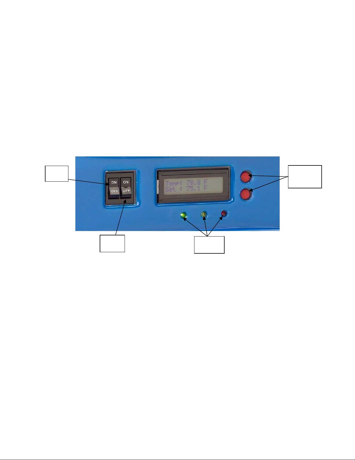
3. To Operate the Unit follow these procedures:
a. Place unit power switch in off position
b. Place compressor/heater power switch in off position.
c. Locate unit power cord supplied and attach to rear of unit in the bottom
receptacle. Plug system heater (if used) into outlet on back of chiller unit.
Temperature controller of unit will automatically control both internal chiller
of unit and an external heat source.
Note: Check heater wattage for appropriate size.
d. Plug unit power cord into a 115V grounded outlet that is on a separate
circuit. Do not plug unit into a non-grounded outlet as this may cause
damage to unit and void warranty.
a
dthismanual
s
afetyand
l
owedto insure
y
CAUTION: Make sure water is flowing through unit at a
minimum of 360 GPH and not more than 1100 GPH. NEVER
OPERATE CHILLER/HEATER WITHOUT WATER FLOWING
THROUGH SYSTEM!
6

UNIT PREPARATION AND OPERATION
e. Set Master switch to on position. LCD display on temperature controller
will power up indicating set point temperature and water circulating
temperature. Allow several minutes for the temperature controller to
display correct tank temperature and pressure to equalize.
f. Select desired tank temperature on LCD display by adjusting temperature
controller (red buttons on right side of LCD display).
g. Set Standby switch to On position. Temperature controller will now take
command of determining whether cooling or heating is required and
automatically control tank temperature.
Note: See following section for temperature controller functions.
Master
Switch Adjust
Set
Temperature
Standby
Switch Indicator
Lights
4. Temperature Controller Indicator Lights: There are three indicator lights
below the LCD display; green, amber, and red. These lights indicate the
current condition of the system as follows:
•No Lights Illuminated: Temperature stabilized to within ±.5°F of set
point and within differential parameters.
•Green Light Illuminated: System chiller is operating and lowering water
temperature to set (desired) temperature.
•Green Light Flashing: System safety has been initiated and 3-minute
time delay has begun. Possible cause: power failure, unit startup.
•Amber Light Flashing: System temperature is above or below 5°F of set
(desired) water temperature. Possible causes: initial unit setup deviation,
water added to tank, power failure.
•Red Light Illuminated: System heater is operating and raising water
temperature to set (desired) temperature.
•Red Light Flashing: System safety has been initiated and 3-minute time
delay has begun. Possible cause: power failure, unit startup.
7
Note: If indicator lights continue flashing after 3 minute delay, turn off
Standby and Master Switches and seek service.

UNIT CARE AND MAINTENANCE
The Aquatherm Model AT-5000 Aquarium Chiller has been designed to provide
years of efficient and reliable service with a minimum amount of maintenance.
a
dthismanual
s
afetyand
l
owedto insure
y
IMPORTANT: Always remove power from the chiller before
performing any cleaning or maintenance activities.
CLEANING:
•The condenser fins on the top of the unit must be kept clean for the unit to
operate properly. Inspect and clean the condenser fins weekly by wiping with
a dry cloth, soft bristle brush, or vacuuming. Be careful not to bend over
condenser fins.
•The plastic housing cover should be wiped with a soft damp cloth. Do not use
any caustic cleaners, as they could scratch of discolor the finish.
•Do not attempt to clean the inner water chambers with any brush that is wire
wound. There is a chance of damaging the delicate internal surfaces. If
cleaning is required, a separate mild chlorine bleach solution is recommended
to remove organic material and a dilute solution of muriatic acid is
recommended for removing mineral deposits. Rinse system and all parts
thoroughly after cleaning before returning unit to service.
a
dthismanual
s
afetyand
l
owedto insure
y
WARNING: Do not perform both internal cleaning operations at
the same time as the combination of chlorine and acid may
cause serious injury or death! Be sure to wear appropriate
protection when using chemical cleaners.
8

9
SAFETY GUIDELINES
a
dthismanual
s
afetyand
l
owedto insure
y
CAUTION: DO NOT STORE UNIT IN FREEZING
TEMPERATURES, UNLESS ALL WATER IS DRAINED FROM
SYSTEM.
a
dthismanual
s
afetyand
l
owedto insure
CAUTION: NEVER OPERATE CHILLER/HEATER WITHOUT
WATER FLOWING THROUGH SYSTEM.
a
dthismanual
s
afetyand
l
owedto insure
y
CAUTION: NEVER LIFT UNIT WHILE IN OPERATION OR
POWER IS SUPPLIED TO UNIT. UNIT IS HEAVY. USE PROPER
LIFTING PROCEDURES WHEN LIFTING UNIT. USE THE
LIFTING PROCEDURES INCLUDED ON SEPARATE PAGE
WHEN LIFTING UNIT.
SERVICING UNIT
For service, first contact your local dealer or authorized sales agency from which
you purchased the unit. If unable to contact your nearest representative, you
may reach Aquatherm at (785) 671-3566, by fax at (785) 671-4292, or by email,
[email protected]. Do not lay unit on its sides or top to drain. Any signs of
misuse, tampering, or lack of controlled maintenance, subject to Aquatherm
inspection, will void warranties. Failure to comply with this warning will void all
warranties.
LIMITED WARRANTY
Aquatherm warrants this product to be free from defective materials and
workmanship for one year from the date of purchase.
Copyright ©2004 - Aquatherm®
Table of contents
Popular Chiller manuals by other brands

Carrier
Carrier 30HH Installation and maintenance instructions

Carrier
Carrier PH4G-K Series installation instructions

Itelco Industry
Itelco Industry MQH R 410A Service manual

Daikin
Daikin McQuay MicroTech III manual

York
York Millennium YCAR 0100SC Wiring diagram

Carrier
Carrier GEMINI 09DPS018 Installation, start-up and maintenance instructions