Bosca SOUL 700 User manual

Save These Instructions
Please read this entire manual before you install and use your BOSCA SOUL 700 Pellet Stove.
Failure to follow instructions may result in property damage, bodily injury, or even death.
Owner´s Manual
SOUL 700 Pellet Stove and Insert
Installation and Operating Instructions

OWNER’S MANUAL
WARNING: If your appliance is not properly installed a house fire may result.
For your safety, follow the installation directions. Contact local building or fire
officials about restrictions and installation inspection requirements in your area.
PLEASE read this entire manual before installation and use of this pellet fuel-
burning room heater.
Failure to follow these instructions could result in property damage, bodily
injury, or even death.
Save these instructions.
PROFESSIONAL INSTALLATION IS HIGHLY RECOMMENDED
OWNER´S MANUAL
-1-

INTRODUCTION 3
SAFETY PRECAUTIONS 4
INSTALLATION 5
Specifications (Soul 700 Free Standing) 5
Preparation (Soul 700 Free Standing) 6
Free Standing Kit Assembly Instructions (Soul 700 Free Standing) 6
Clearances (Soul 700 Free Standing) 10
Combustion Air Supply (Soul 700 Free Standing) 12
When Outside Air Supply is not Used (Soul 700 Free Standing) 12
Venting (Soul 700 Free Standing) 13
Installations (Soul 700 Free Standing) 14
Specifications (Soul 700 Insert) 19
Installations (Soul 700 Insert) 20
Venting System (Soul 700 Insert) 23
Installing Surround Panel (Soul 700 Insert) 24
Specifications (Soul 700 Insert) 25
Installation Check List (Soul 700 Insert) 26
Electrical Installation 26
OPERATION 27
Panel Controls 27
Proper Fuel 28
Pre-Start-Up Check 28
Building a Fire 28
Damper Control 29
Opening Door 29
Room Air Fan 29
If Stove Runs out of Pellets 29
Refueling 29
Shutdown Procedures 30
Safety Features 30
Thermostat Installation 30
Modes 30
OPERATING SAFETY PRECAUTIONS 31
MAINTENANCE 32
Maintenance Tool 32
Ash Removal 32
Ash Disposal 34
Vacuum Use 34
Cleaning 34
Blowers 35
Chimney Cleaning 35
Recommended Maintenance Schedule 35
Removal and Replacement of Broken Door Glass 36
TROUBLESHOOTING GUIDE 36
ELECTRICAL DIAGRAM 41
REPLACEMENT PARTS 42
LIFETIME LIMITED WARRANTY 45
TABLE OF CONTENTS
OWNER´S MANUAL
-2-

Thank you for purchasing the BOSCA SOUL 700 Pellet Stove. You are now prepared to burn wood pellets in
the most efficient, convenient way possible. To achieve the safest, most efficient and most enjoyable performance from your stove,
you must do three things:
1) Install it properly;
2) Operate it correctly; and
3) Maintain it regularly.
The purpose of this manual is to help you do all three.
This stove has been independently tested to ASTM E 1509-04 Standard Specification for Room Heaters, Pellet Fuel Burning Type
1, UL 1482-1998 Standard for Solid Fuel Room Heaters, Oregon Administrative Rules for Mobile Homes (814-23-900 through 814-
23-909) and Installation as a Stove Heater.
This pellet stove, when installed, must be electrically grounded in accordance with local codes, or in the absence of local codes,
with the National Electrical Code ANSI/NFPA70.
This appliance is designed specifically for use only with pelletized wood. It is designed for residential installation according to
current national and local building codes as a residential room heater. It is also approved as a mobile home heater, and is designed
for connection to an outside combustion air source.
The stove will not operate using natural draft or without a power source for the blower systems and fuel feed system and must
not be burned with any type of coal (see PROPER FUEL).
This stove is designed to provide the optimum proportions of fuel and air to the fire in order to burn free of smoke and soot. Any
blockage of the air supply to or from the stove will seriously degrade its performance and will be evidenced by a smoking exhaust
and a sooting window. For best operation the ash content of the pellet fuel should be less than 1% and the caloric value
approximately 8200 BTU/LB. Avoid high ash content fuels because this will rapidly fill up the burn pot and eventually cut off the
combustion air supply.
The BOSCA SOUL 700 Pellet Stove should not be used for commercial and industrial installation since operational control is
often not well managed in these settings.
INTRODUCTION
PLEASE READ THIS ENTIRE MANUAL BEFORE INSTALLATION AND USE OF THIS PELLET
FUEL BURNING ROOM HEATER.
FAILURE TO FOLLOW THESE INSTRUCTIONS COULD RESULT IN PROPERTY DAMAGE,
BODILY INJURY OR EVEN DEATH.
KEEP THIS MANUAL HANDY FOR FUTURE REFERENCE.
OWNER´S MANUAL
-3-

§Do not operate your stove if you smell smoke coming from it. Turn it off, do not unplug, monitor it, and call your
dealer.
§Never use gasoline, gasoline-type lantern fuel, kerosene, charcoal lighter fluid, or similar liquids to start or “freshen up” a
fire in this stove. Keep all such liquids well away from the stove while in use.
§Never block free airflow through the open vents of the stove.
§Never try to repair or replace any part of the stove unless instructions are given in this Manual. All other work should
be done by a trained technician.
§The stove will not operate during a power outage. If an outage does occur, check the stove for smoke spillage and
open a window if any smoke spills into the room.
§Disconnect the power cord before performing any maintenance or repairs on the stove.
NOTE: Turning the stove "off" does not disconnect all power from the stove.
§Do not unplug the stove if you suspect a malfunction. Turn the stove off, immediately inspect it, and call your dealer.
§Keep foreign objects out of the hopper.
§Do not throw this Manual away. This Manual has important operating and maintenance instructions that you will need
at a later time. Always follow the instructions in this Manual.
§Do not place clothing or other flammable items on or near your stove.
§The viewing door must be closed and latched during operation.
§Do not operate the stove if the flame becomes dark and sooty or if the burn pot overfills with pellets. Turn the stove
off, immediately inspect it, and call your dealer.
§The stove is hot while in operation. Keep children, clothing, and furniture away. Contact may cause skin burns. Educate
all children of the danger of a high temperature stove. Young children should be supervised when they are in the same
room as the stove.
§If the stove is installed in a room without air conditioning, or in an area where direct sunlight can shine on it, it is possible
this can cause the temperature of the stove to rise to operational levels. One of the sensors could then make the
convection fan and/or feed system start on its own. It is recommended that the stove be unplugged when not in use
for extended periods of time (i.e. during the summer months).
§Contact your local building officials to obtain a permit and information on any installation restrictions or inspection
requirements in your area. Notify your insurance company of this stove as well.
§This unit must be properly installed to prevent the possibility of a house fire. The instructions in this Manual must be
strictly adhered to. Do not use makeshift methods or compromise in the installation.
§Allow the stove to cool before carrying out any maintenance or cleaning. Ashes must be disposed of in a metal container
with a tight lid and placed on a non-combustible surface well away from the home structure.
§The stove must be connected to a standard 120V, 60 Hz grounded electrical outlet. Do not use an adapter plug or
sever the grounding plug. Do not route the electrical cord underneath, in front of, or over the stove.
§The exhaust system should be checked a minimum of twice a year for any buildup of soot or creosote.
§The exhaust system must be completely airtight and properly installed. The pellet vent joints must be sealed with RTV
500ºF (260ºC) silicone sealant, or with UL-181-AP foil tape. Fasten with at least 3 screws.
§Your stove requires periodic maintenance and cleaning. Failure to maintain your stove may lead to smoke spillage into
your home.
§This stove is designed and approved for pelletized wood fuel only. Any other type of fuel burned in this heater will void
the warranty and safety listing.
§When installed in a mobile or manufactured home, the stove must be bolted to the floor and have outside combustion
air (per H.U.D. requirements). Check with local building officials.
§THIS STOVE MUST NOT BE INSTALLED IN A BEDROOM OR SLEEPING ROOM.
§BOSCA grants no warranty, implied or stated, for the installation or maintenance of your stove, and assumes no responsibility
for any consequential damages.
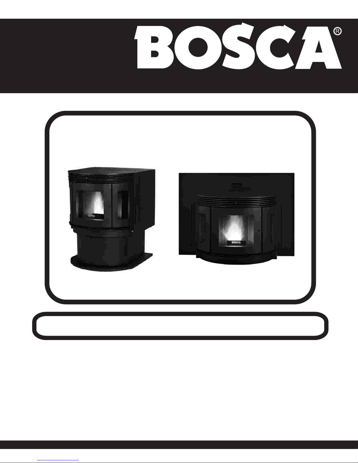
OWNER´S MANUAL
-4-
SAFETY PRECAUTIONS

INSTALLATION
SPECIFICATIONS Soul 700 Pellet Free Standing
TOP VIEW
fig. Nº1
30.2 in.
(767 mm.)
FRONT VIEW
26.8 in.
34.6 in.
(683 mm.)
(880 mm.)
Freestanding
26.8 in.
(683 mm.)
Width:
Height:
Depth:
Weight:
26.8 in.
34.6 in
30.2 in
419 lbs.
Flue Size:
Hopper Capacity:
Emmisions Rate:
Burn Rate:
BTU Range:
Approved Installations:
3" or 4"
80 lbs.
2.5 grs/hour (EPA Certified)
0.75 lbs to 5.5 lbs per hour
8,200 to 47,000
Mobile Home, Alcove, Conventional
OWNER´S MANUAL
-5-

Factory packaging must be removed, and some minor assembly work is required prior to installation. Access to the rear of the
stove is necessary.
1.- PEDESTAL ASSEMBLY (fig. Nº2)
a.- Unpack the stove.
b.- Unbolt stove from pallet.
- 4 hex head bolts
c.- Carefully lay the stove on its back.
2.- ASH BOX ASSEMBLY (fig. Nº3)
a.- Remove firebox floor plate by removing 6 bolts
(1/4" flat head). See Fig. Nº2
b.- Unpack Ash Box.
c.- Align ash box to stove firebox bottom, start
front bolts (1/4" hex head). Adjust and install
remaining (1/4" hex head) bolts.
Do not fully tighten until alignment of all bolts are
started, press ash box up to stove bottom and
tighten.
NOTE: Make sure to get a tight seal. A leak
may cause stove to burn incorrectly.
fig. Nº2
fig. Nº3
FIRE BOX
FLOOR PLATE
ASH BOX
PREPARATION Soul 700 Pellet Free Standing
FREE STANDING KIT ASSEMBLY INSTRUCTIONS Soul 700 Pellet Free Standing
-6-
OWNER´S MANUAL

3.- PEDESTAL ASSEMBLY (fig. Nº4)
a.- Unpack pedestal assembly.
b.- Lay pedestal assembly on it's back.
c.- Line up four (1/4" hex head) bolts to stove bottom.
d.- Start all four holes but do not tighten untill all four are aligned.
e.- Once all four holes are aligned, securely tighten the four bolts.
fig. Nº4
fig. Nº5
PEDESTAL
ASSEMBLY
4.- STAND THE STOVE UP (fig. Nº5)
a.- Carefully raise the stove from back until resting
solid.
OWNER´S MANUAL
-7-

6.- HOPPER TOP ASSEMBLY (fig. Nº7)
5. SIDE PANEL ASSEMBLY
(fig. Nº6)
a.- Unpack side panels.
b.- Left side panel has hopper switch located at
top front.
c.- Connect hopper switch wires by sliding female
wire connection over male spade connectors on
hopper switch.
d.- Align left panel into place
e.- Install bolts through pedestal into side panel.
f.- Loosely tighten
g.- Install top side panel bolts loosely
h.- Align side panel and tighten bolts.
i.- Use same instruction on right side panel, except
hopper switch connection
fig. Nº6
fig. Nº7
SIDE PANELS
-8-
OWNER´S MANUAL
a.- Unpack hopper top assembly.
b.- Slide hopper top down in between side panels.
c.- Adjust to be level with side panels
d.- Screw front three (3/8" Oval Head Phillips)
screws into stove hopper front.
e.- Adjust for level and install screws to side panels.
f.- Tighten all screws securely, make sure all sides
fit tightly to hopper.

7.- HOPPER DOOR ASSEMBLY (fig. Nº8)
8.- BACK PANEL ASSEMBLY (fig. Nº9)
fig. Nº8
fig. Nº9
a.- Unpack hopper door assembly.
b.- Place hopper top over hopper.
c.- Align top squarely and make sure hopper
switch aligns with contact on hopper door.
d..- Align five (3/8" Oval Head Phillips) screws on
back of hopper top back to hopper door hinge
and tighten.
e.- Lift hopper door to ensure it moves freely and
aligns with hopper switch.
a.- Unpack back panel assembly.
b.- Align the back panel to predrilled holes on
hopper top assembly and side panels.
c.- Install nine (3/8" Oval Head Phillips) screws.
d.- Align lower back panel to pre drilled holes on
side panels.
e.- Install six (3/8" Oval Head Phillips) screws, and
tighten securely.
-9-
OWNER´S MANUAL

The BOSCA SOUL 700 Pellet Stove has been tested and listed for installation in residential, mobile home
and alcove applications.
fig. Nº10
NOTE: ceramic tile, or any tile, requires a continuous sheet beneath to prevent the possibility of embers falling through to
the combustible floor if cracks or separation should occur in the finished surface, this would include floor protection for Built-
in raised hearths. Check local codes for approved alternatives.
Clearances are measured from the sides, back and face (door opening) or stove body (refer to fig Nº 11).
The clearances may only be reduced by means approved by the regulatiory authority.
FLOOR PROTECTION
Freestanding installations, minimum 33" wide by 36" deep. The stove must be placed on a continuous (grouted joints)
noncombustible material such as ceramic tile, cement board, brick, 3/8” millboard or equivalent, or other approved or listed
material suited for floor protection (refer to Fig Nº 10) .
FLOOR PROTECTION
CLEARANCES Soul 700 Pellet Free Standing
(76 mm.)
3 in.
(76 mm.)
3 in.
(25 mm.)
1 in.
MINIMUM
6 in. (152 mm.)
-10-
OWNER´S MANUAL

fig. Nº12
WALL CLEARANCES
(76 mm.)
3 in.
7 in.
3 in.
(76 mm.)
Back wall
Side wall
fig. Nº11
FRONT VIEW TOP VIEW
DO NOT USE MAKESHIFT MATERIALS OR COMPROMISES IN THE
INSTALLATION OF THIS UNIT.
INSTALL VENT WITH CLEARANCES SPECIFIED BY
THE VENT MANUFACTURER.
ALCOVE CLEARANCES
OWNER´S MANUAL
-11-
(178 mm.)
(1400 mm.)
(minumum height)
55 in.
(510 mm.)
20 in.
(915 mm.)
(maximum depth)
36 in.
(76 mm.)3 in.
(178 mm.)
7 in.

If outside air is not used, it is important that combustion air is easily available to the air inlet. A closeable outside air register can
be used in tightly insulated homes.
OUTSIDE TERMINATION MUST BE 12" MIN. FROM
THE EXHAUST TERMINATION
For Mobile home installations only: 2” inside diameter pipe may be used for first 5 feet of combustion air supply run. From
5 to 10 feet use 2 3/4” inside diameter pipe. No combustion air supply may exceed 20 feet.
For a mobile home installation, the stove must be connected to an outside source of combustion air. A 2” inside diameter metallic
pipe, either flexible or rigid, may be attached to the inlet at the stove’s rear (refer to Fig. Nº 13). A rodent guard / wind hood
(1/4” minimum wire mesh) must be used at the termination. All connections must be secured and airtight by using the appropriately
sized hose clamp and/or UL-181-AP foil tape.
COMBUSTION AIR SUPPLY Soul 700 Pellet Free Standing
WHEN OUTSIDE AIR IS NOT USED Soul 700 Pellet Free Standing
OWNER´S MANUAL
-12-
fig. Nº13
SELECT A LOCATION BETWEEN
FRAMING MEMBRES FOR THE
OUTSIDE AIR HOLE
SEAL THE AREA AROUND
THE TUBE TO PREVENT AIR
FROM ENTERING THE WALL
SEAL THE
VENT WITH
SILICONE
2" FLEX DUCT
NON COMBUSTIBLE
CUT A MINIMUN 2"
DIAMETER HOLE IN
THE WALL
RAIN
HOOD WITH
RODENT
SCREEN
WALL
COVER
PLATE
SOURCES OF OUTSIDE COMBUSTION AIR
In Fireplaces
- Chimney top.
- Ash clean out door.
For freestanding installations
- A hole in floor near stove rear terminating only in a
ventilated crawl space.
- A hole in the wall behind the stove.

EQUIVALENT VENT LENGTH (EVL)
The longer the run of pipe in your installation, the more restrictions there is in the system. Therefore, larger diameter pipe should
be used.
Use 4” pipe if you have more than 15 feet of equivalent vent length. Horizontal runs shall not exceed 10 feet of EVL. It is
recommended that vertical runs be a minimum of 8 feet.
This is a pressurized exhaust system. All vent connector joints must be sealed with 500 ºF (260 ºC) RTV silicone sealant
to ensure consistent performance and avoid smoke spillage. All horizontal connector joints must be sealed with UL-181-
AP foil tape. We required that all vertical vent connector joints be secured with a minimum of 3 screws.
To calculate EVL, use the following conversions:
90º elbow or “T” 5 equivalent feet
45º elbow 3 equivalent feet
Horizontal Pipe Run 1 equivalent foot per actual foot
Vertical Pipe Run 0.5 equivalent foot per actual foot
NOTE: At altitudes above 3,000 feet, we suggest the use of 4” diameter vent at an EVL of 7 feet or more.
DO NOT CONNECT THIS UNIT TO A CHIMNEY FLUE SERVING
ANOTHER APPLIANCE.
DO NOT INSTALL A FLUE DAMPER IN THE EXHAUST VENTING
SYSTEM OF THIS UNIT.
INSTALL VENT AT CLEARANCES SPECIFIED BY THE VENT
MANUFACTURER.
The BOSCA SOUL 700 Pellet Stove is certified for use with listed TYPE L-Vent, 3” or 4” diameter in size. The stove was tested
with Simpson Duravent brand. Class “A” chimney is not required. Refer to the instructions provided by the vent manufacturer,
especially when passing through a wall, ceiling or roof.
VENTING Soul 700 Pellet Free Standing
OWNER´S MANUAL
-13-
DO NOT CONNECT TO ANY AIR DISTRIBUTION DUCT OR SYSTEM
SECURE EXHAUST VENTING SYSTEM TO THE APPLIANCE WITH
AT LEAST 3 SCREWS. ALSO SECURE ALL CONNECTOR PIPE
JOINTS WITH AT LEAST 3 SCREWS THROUGH EACH JOINT.
OWNER´S MANUAL

fig. Nº14
fig. Nº15
GALVANIZED EXTERIOR
(STAINLESS STEEL FOR
CORVENT)
BLACK
INTERIOR
Fig 14. Locate terminations:
a) not less than 3 feet above any forced air inlet
located with 10 feet;
b) not less than 4 feet below or horizontally from, or
one foot above, any door, window or gravity air inlet
into any building;
c) not less than 2 feet from an adjacent building and
not less than 7 feet above grade when located
adjacent to a public walkway. Mobile home
installations must use a spark arrester.
NOTE: In Canada, where passage through a wall of
combustible construction is desired, the installation
shall conform to CAN/CSA - B 365.
HORIZONTALL TERMINATION
HORIZONTALLY THROUGH WALL
(Fig. Nº14)
NOTE: Follow L-Vent chimney manufacturer’s instructions.
• Position stove, adhering to clearances show in Figure Nº11
• Locate position of hole in wall; directly behind stove exhaust vent.
• Always maintain 3” clearance from combustible materials.
• Install L-Vent wall thimble per L-Vent manufacturer’s instructions (refer fig. Nº 15).
•Attach enough piping to penetrate and extend at least 12” beyond exterior walls. An 5-foot vertical pipe run is suggested
where possible to reduce the possibility of smoke spillage in the event of a loss of negative pressure.
•Attach cap and seal outside wall thimbles with
non-hardening waterproof mastic.
•Termination should not be located so that hot
exhaust gases can ignite trees, shrubs, or grasses
or be a hazard to children. Exhaust gases can
reach temperatures of 500ºF and cause serious
burns if touched.
12 INCHES
MINIMUN
SQUARE
HORIZONTAL
CAP
OPTIONAL
HOUSE
SHIELD
FREESTANDING INSTALLATIONS Soul 700 Pellet Free Standing
WALL THIMBLE
OWNER´S MANUAL
-14-

VERTICALLY WITH NEW CHIMNEY SYSTEM
( Refer to Figures 16a-16b)
fig. Nº16b
4 FT.
fig. Nº16a
24" MIN ATTIC
INSULATION
SHIELD
CEILING
SUPPORT/
FIRESTOP
SPACER
PIPE
ADAPTER
TEE WITH
CLEAN-OUT
ADAPTER
24" MIN
NOTE: Follow L-Vent chimney manufacturer’s instructions.
OPTION: Install L-Vent elbow in place of clean-out tee. Locate stove. Drop plumb bob to center of tee
outlet, mark point on ceiling. Install ceiling support and L-Vent pipe per L-Vent manufacturer’s instructions.
•Always maintain 3” clearance from combustible materials. When passing through additional floors
or ceilings, always install firestop spacer.
•After lining up for hole in roof, cut either around or square hole in roof, always 3” larger all the
way around pipe. Install upper edge and sides of flashing under roofing materials, nail to the roof
along upper edge. Do not nail lower edge. Seal nail head with non-hardening waterproof mastic.
•Apply non-hardening, waterproof mastic where the storm collar will meet the vent and flashing.
Slide storm collar down until it sits on the flashing. Seal and install cap. Mobile home installations must
use a spark arrester.
FIRESTOP
OWNER´S MANUAL
-15-

VERTICALLY INTO EXISTING CHIMNEY SYSTEM
( Refer to Figures 17a-17b)
fig. Nº17afig. Nº17b
Adapters are available to adapt from 3” L-Vent to 6” or 8” Class-A chimney. (Figure 17a)
As an alternative, 3” or 4” L-Vent can be run inside existing chimney to termination. (Figure 17b).
This is the preferred method.
24" MIN ATTIC
INSULATION
SHIELD
CEILING
SUPPORT/
FIRESTOP
SPACER
PIPE
ADAPTER
TEE WITH
CLEAN-OUT
ADAPTER
24" MIN ATTIC
INSULATION
SHIELD
CEILING
SUPPORT/
FIRESTOP
SPACER
PIPE
ADAPTER
TEE WITH
CLEAN-OUT
ADAPTER
Follow guidelines for equivalent
OWNER´S MANUAL
-16-

VERTICALLY INTO EXISTING MASONRY FIREPLACE
OMNI Approved
fig. Nº19
NOTE: Follow L-Vent chimney manufacturer’s instructions.
•Have the masonry chimney inspected by a qualified chimney sweep or installer to determine its structural condition.
•You will need a pipe length equal to the chimney height from the hearth. If outside combustion air is to be used, you will need a
pipe length equal to the chimney height plus 18 inches.
•Install a blanking plate and the chimney pipe, and if used the outside air pipe..
Attach the L-Vent adapter, a section of pipe and clean out tee, making sure the clean-out tee is centered in the chimney flue area.
Use RTV, metallic tape, and a minimum of three self-taping screws at all joint connections to ensure a tight seal.
Install and seal the top plate from step 3 with non-hardening mastic. Slip the storm collar over the pipe, and while
holding the pipe at the proper elevation, affix the collar with a minimum of three 1/4” stainless steel sheet metal
screws. Seal all joints and seams around the collar.
Connect the horizontal pipe by pushing it through the hole in the masonry and lining it up with the branch in the
tee. Push the pipe into the tee while twisting it to lock it into the tee.
If desired, once the horizontal pipe is in place, the space between the pipe and masonry may be filled with high-
temperature grout.
Install the trim collar. An adjustable pipe length and adapter may be needed to finish the connection to the stove.
TEE FLEX
LINER
FLEX
LINER
OWNER´S MANUAL
-17-
( Fig. Nº18)
fig. Nº18
TEE
REDUCTION
COLLAR OR
TRIMCOLLAR

fig. Nº19
INSTALLATION THROUGH SIDE OF MASONRY CHIMNEY
(Fig. Nº 19)
NOTE: Follow L-Vent chimney manufacturer’s instructions.
•Position the stove, adhering to the clearances in figure Nº 11. Mark the center of the hole where the pipe is to pierce the
masonry chimney. It will be necessary to break out the masonry around the location of the pipe center mark. Use a 4-inch
diameter hole for 3-inch pipe and 5-inch diameter hole for a 4-inch pipe.
•Measure and build chimney top plate. Cut out holes for chimney pipe, and if used cut necessar
holes for the outside air pipe. Install the tee on the bottom of the vertical pipe system and lower it
down the chimney until the center branch of the tee is level with the center of the hole in the masonry, as shown in
Figure Nº19.
•Install and seal the top plate from step 3 with non-hardening mastic. Slip the storm collar over the
pipe, and while holding the pipe at the proper elevation, affix the collar with a minimum of three
1/4” stainless steel sheet metal screws. Seal all joints and seams around the collar.
•Connect the horizontal pipe by pushing it through the hole in the masonry and lining it up with
the branch in the tee. Push the pipe into the tee while twisting it to lock it into the tee. If desired,
once the horizontal pipe is in place, the space between the pipe and masonry may be filled with
high-temperature grout.
•If desired, once the horizontal pipe is in place, the space between the pipe and masonry may be filled with
high-temperature grout.
•Install the trim collar. An adjustable pipe length and adapter may be needed to finish the connection
to the stove.
OWNER´S MANUAL
-18-

TOP VIEW
fig. Nº20
FRONT VIEW
Insert
Width:
Height:
Total Depth:
Weight:
40 in. (standard) - 45 in. (oversize)
30.5 in. (standard) - 34 in. (oversize)
27.4 in
309 lbs.
Flue Size:
Hopper Capacity:
Emmisions Rate:
Burn Time
BTU Range:
Approved Installations:
3" or 4"
55 - 75 adjustable hopper
2.5 grs/hour (EPA Certified)
0.75 lbs to 5.5 lbs per hour
8,200 to 47,000
Mobile Home, Alcove, Conventional
SPECIFICATIONS Soul 700 Pellet Insert
(Fig. Nº20)
30.5 in.
(775 mm.)
(standard)
40 in.
(1017 mm.)
(standard)
34 in.
(864 mm.)
(oversize with)
45 in.
(1143 mm.)
(oversize with)
27.4 in.
(697 mm.)
26.8 in.
(683 mm.)
SIDE VIEW
12.6 in.
(320 mm.)
14.8 in.
(377 mm.)
22.4 in.
(570 mm.)
Adjustable
19.5 in. to 22.5 in.
OWNER´S MANUAL
-19-
Table of contents
Other Bosca Stove manuals
Popular Stove manuals by other brands

Enviro
Enviro MINI-2 owner's manual

Infinity
Infinity 890 HDBF Instruction for user, Installation & Servicing

Arada
Arada Holborn Gas manual

HWAM
HWAM Vivaldi User, installation and servicing instructions

Horus
Horus VERTIGO 12.0 Operating, installation and maintenance manual

Charnwood
Charnwood Cove 2B Operating & installation instructions