Bosch Rexroth AG VT 3000 User manual

1/8
Analog amplifier
Type VT 3000
Component series 3X
RE 29935/10.12
Replaces: 11.06
Overview of contents Features
– Suitable for the control of pilot operated proportional direc-
tional valves (type .WRZ, up to component series 6X) and
direct operated proportional pressure valves (type DBEP6
and 3DREP6, each component series 1X) without electrical
position feedback
– Four command values adjustable with potentiometers
– Four command value call-ups with LED display
– Differential input
– Step function generator
– Ramp generator
– Two pulsed current output stages
– Polarity protection for the voltage supply
Note:
When supplied the amplifiers have a ramp time of 5 s (setting
of the ramp time of 1 s see page 6).
Contents Page
Features 1
Ordering code 2
Functional description 2
Block circuit diagram / pin allocation 4
Technical data 5
Output curve 6
Indicator / Adjustment elements 6
Unit dimensions 7
Engineering notes / maintenance instructions /
supplementary information 7
H4162
similar figure
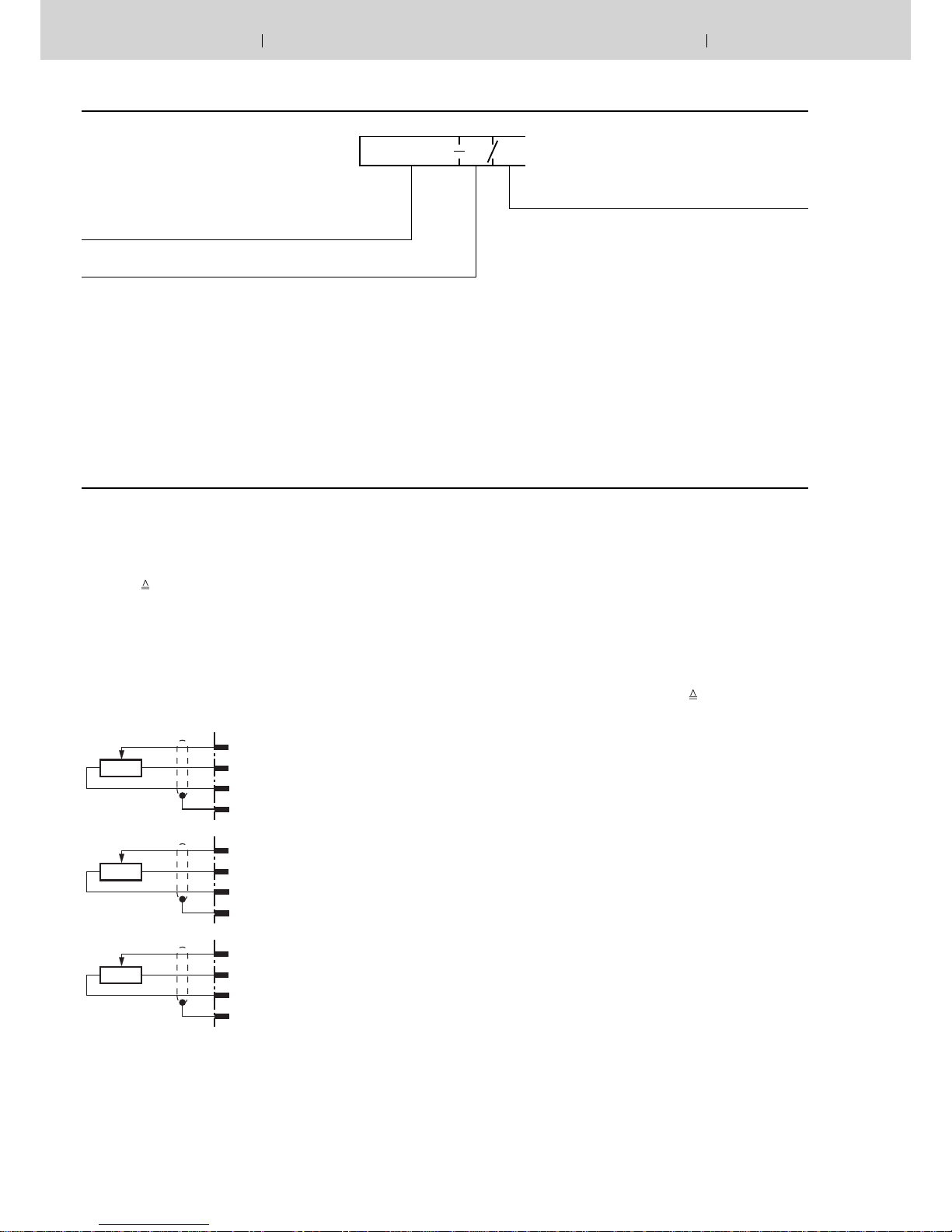
5 K
10c (10a, 8a, 12a)
20c +9 V
20a M0
26a
5 K
5 K
10c (10a, 8a, 12a)
26c –9 V
20a M0
26a
10c (10a, 8a, 12a)
20c +9 V
26c –9 V
26a
2/8 Bosch Rexroth AG Hydraulics VT 3000 RE 29935/10.12
Ordering code
Amplifier for prop. directional valves (type .WRZ, up to
component series 6X) and prop. pressure valves (type
DBEP6 and 3DREP6, each component series 1X)
Component series 30 to 39 = 3X
(30 to 39: unchanged technical data and pin allocation)
Further details in plain text
VT 3000 3X *
Functional description
With the command value inputs 1 to 4 command values can
be called up [1] by operating the corresponding relays (K1
to K4). The command value voltage is either given directly
through the controlled voltages ±9 V of the power supply [10]
or via an external command value potentiometer. For this in-
puts ±9 V ±100 % 1) is valid. If these four command value
inputs are directly connected to the controlled voltages ±9 V
four different command values can be set at the potentiom-
eters „w1“ to „w4“. When using external command value po-
tentiometers at these inputs the internal potentiometers also
function as weakeners or limiters when these are not set to
maximum.
External command value potentiometer
Inputs
Control
solenoid „B“
Inputs
Control
solenoid „A“
Inputs
Control
solenoid
„A“ and “B“
Which command value is momentarily called up is indicated
by the LEDs „H1“ to „H4“. If more than one command value
is called up simultaneously the input with the highest num-
ber has priority. Example: If command value 1 and command
value 3 are activated simultaneously the command value 3
becomes effective.
A further output of the card provides a supply voltage for the
command value call-ups which can be switched over from
+9 V to –9 V with the relay K6 1).
All relays on the card are switched with 24 VDC (smoothed).
Additionally, the direct command value input 5 is available for
the input voltage 0 to ±6 V. Valid is ±6 V ± 100 % 1).
The command value input 6 is a differential input (0 to ±10 V).
If the command value is presented by a separate electronics
with a different reference potential this input must be used.
When switching on or off the command value it must be taken
care that both signal lines are either separated from or con-
nected to the input.
All command values are summated with the correct value and
sign before they are connected further [3].
The added ramp generator [4] produces a ramp-like output
signal from the jump-like given input signal. The time constant
can be set with the potentiometers „t1“ to „t5“. The ramp time
given refers to a command value jump of 100 % and can be,
according to the setting through the selection via jumpers (J5,
J6), approximately 1 s or 5 s. If a command value jump small-
er than 100 % is switched to the input of the ramp generator
the ramp time shortens appropriately.
Card holder:
– Type VT 3002-1-2X/32D, see data sheet 29928
Single card holder without power pack
1) Reference potential for the command values 1 to 5
is M0 (measuring zero)

Hydraulics Bosch Rexroth AGRE 29935/10.12 VT 3000 3/8
Note:
When using an external time potentiometer the internal
potentiometer for the ramp time must be set at maximum.
The maximum ramp time decreases because the resist-
ance of the external potentiometer is connected parallel to
the internal potentiometer (approx. 500 kΩ)!
By switching the relay K5 or through an external bridge the
ramp time is set to its minimum value (approx. 30 ms).
The output signal of the ramp generator [4] runs parallel to
the summator [6] and the step function generator [5]. On com-
mand values > ±1 % the step function generator produces a
polarity-dependent constant step signal with the command
value voltages which is added to the output signal of the
ramp generator. This step function causes the rapid travelling
across the overlapping area of the valve spool.
Functional Description (Continuation)
The output signal of the summator [6] is the command current
value and is led to the two current output stages [7] and to the
test point „W“ on the front plate of the card. A voltage of +6 V
at the command value test point „W“ corresponds to a com-
mand value of +100 %.
A positive command value signal at the input of the amplifier
controls the output stage for solenoid „B“, a negative com-
mand value signal the output stage for solenoid „A“. If the
command value signal is smaller than ±1 % (step function still
ineffective) a pilot current of 20 mA flows through both sole-
noids. The actual values of the currents through the two sole-
noids can be measured separately at the test points „IA“ (so-
lenoid „A“) and „IB“ (solenoid „B“). Here a current of 800 mA
corresponds to a voltage of 800 mV.
LED „H11“ lights up when the system is powered up.
LED „H12“ („Ready for operation“) lights up to indicate trou-
ble-free operation as long as:
– the internal power supply (±9 V) is functioning properly
– there is no short-circuit in the solenoid lines
In the event of a fault, both output stages are immediately de-
energized and the signal „Ready for operation“ is cancelled.
Once the fault has been cleared, the amplifier card is immedi-
ately operable and LED „H12“ lights up again.
[ ] = Allocation in block circuit diagram page 4
External time potentiometer and ramp „Off“
14a
14c
26a
500 K
14a
14c
Ramp „controllable“
min. time at 0 Ω
max. time at 500 kΩ
Ramp „on/off“
i
u
u
K5
10c
10a
8a
12a
12c
K1.1 K2.1 K3.1 K4.1
w4
w3
w2
w1
+
K6
H1
H2
K3
K2
K1
H4
H3
K4
K5
K6
16a
26c
20c
2a
18a
16c
6c
6a
4a
8c
4c
18c
30a
24a
22a
28a
32a
+U
B
26a
J5, J6
u
2,5 A T
20a
I
B
32c
X1
0 V
28c
–
10
I
A
W
8
7
7
7
6
5
43
2
1
=
14c
14a
t
–1
+9 V
M0
–9 V
9
H12
H11
F F F F
1
F
6
F
F
F
F
F
X1
6
6
7
i
u
F
F
F
F
6
4/8 Bosch Rexroth AG Hydraulics VT 3000 RE 29935/10.12
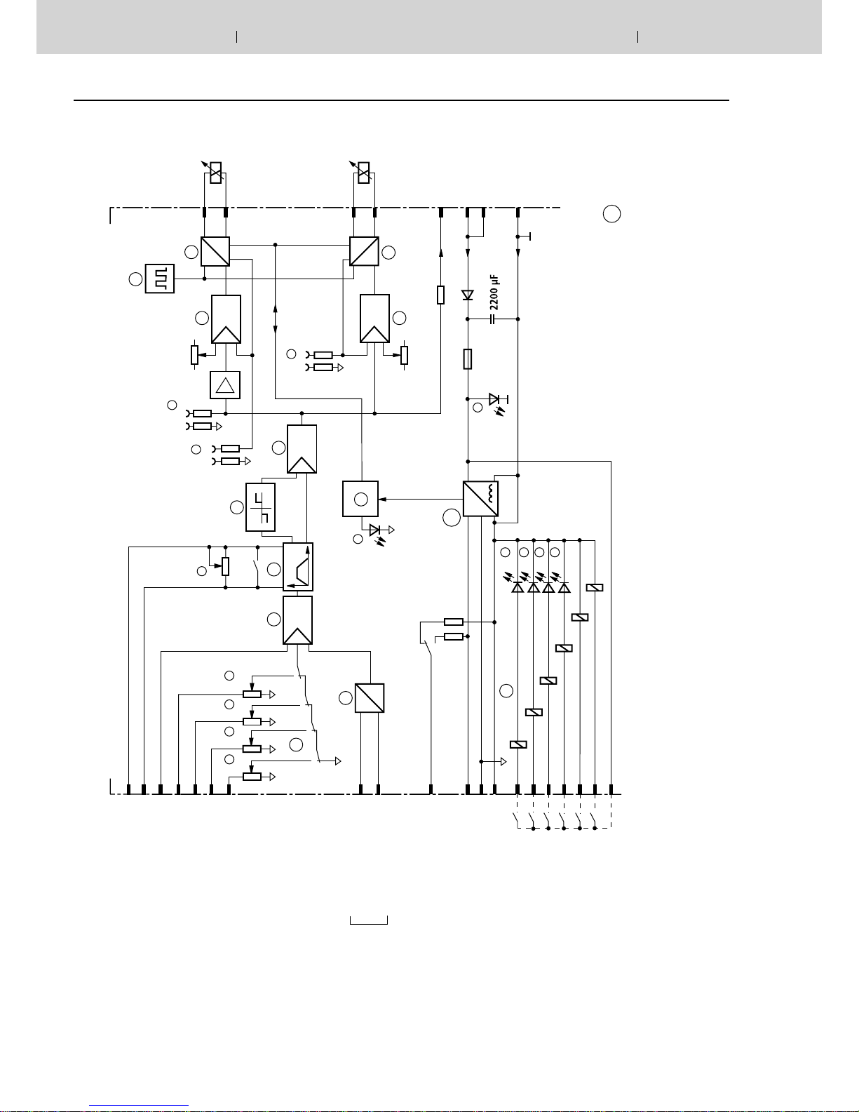
Block circuit diagram / pin allocation
Positive comm. value
controls solenoid „B“
Negative comm. value
controls solenoid „A“
External ramp
Command value 5 ±6 V
Command value 4 ±9 V
Command value 3 ±9 V
Command value 2 ±9 V
Command value 1 ±9 V
Command value 6
Reference potential
Differential
input
Aux. voltage ±9 V
Measuring zero (M0) is
raised by 9 V compared
to 0 V operating voltage!
Call-up command value 1
Call-up command value 2
Call-up command value 3
Call-up command value 4
Call-up „Ramp off“
Call-up „Switch-over aux. voltage
“
Relay call-up voltage (+ 24 V)
Current command value at „w“
0 to +6 V for solenoid „A“
0 to –6 V for solenoid „B“
Current actual value IA at „IA“
Current actual value IB at „IB“
Biasing
current
solenoid „A“
Solenoid „A“
Solenoid „B“
Comm. value
after ramp
Operating
voltage
H1 to H4 = LED-display for com-
mand value call-ups
H11 = „power on“
H12 = „Ready for operation“
K1 to K6
= Call-up relais
w1 to w4
= Command values
t= Ramp time
1Command values
2Differential input
3; 6 Summator
4Ramp generator
5Step function generator
7Current output stage
8Pulse generator
9Monitorings
10 Power supply
F = on front plate
For explanation of
jumpers (J5, J6) and
arrangement of in-
dicator and adjust-
ment elements, see
page 6
Biasing current
solenoid „B“

Hydraulics Bosch Rexroth AGRE 29935/10.12 VT 3000 5/8
Technical data (For application outside these parameters please consult us!)
Operating voltage 1) UB24 VDC +60 % –5 %
Operating range:
– Upper limit value uB(t)max 39 V
– Lower limit value uB(t)min 22 V
Power consumption PS< 50 VA
Current consumption I< 1 A (with loading current)
Fuse IS2.5 A slow
Inputs:
– Command values 1 to 4 Ue±9 V (reference potential is M0)
– Command value 5 Ue±6 V (reference potential is M0)
– Command value 6 (differential input) Ue0 to ±10 V; Re = 100 kΩ
Ramp time (setting range) t30 ms to approx. 1 s or 5 s
Outputs:
– Output stage
• Solenoid current/resistance Imax 800 mA; R(20) = 19.5 Ω
• Biasing current IV20 mA ±25 %
• Pulse frequency f 170 Hz ±10 %
– Regulated voltage U±9 V ±1 %; ±25 mA externally loadable
– Measuring sockets
• Current command value „W“ U±6 V; Ri = 5 kΩ
• Current actual value „IA“; „IB“UA; UB0 to 800 mV equivalent 0 to 800 mA
Relay data:
– Nominal voltage Uoperating voltage UB
– Threshold voltage U16.8 V
– Return voltage U2.4 V
– Coil resistance R2150 Ω
Type of connection 32-pin terminal strip, DIN 41612, form D
Card dimensions Euro-card 100 x 160 mm, DIN 41494
Front plate dimensions
– Height 3 HE (128.4 mm)
– Width soldering side 1 TE (5.08 mm)
– Width component side 7 TE
Permissible operating temperature range 0 to 50 °C
Storage temperature range –25 to 85 °C
Weight m0.13 kg
1) To guarantee the max. solenoid current for the solenoid
(19.5 Ω) in the complete solenoid temperature range the
operating voltage must be at least 28 VDC!
Note:
For details regarding environmental simulation test in the
field of EMC (electromagnetic compatibility), climate and me-
chanical stress, see data sheet 30304-U (declaration on envi-
ronmental compatibility).
+
100
%
+
50
%
+
1
%
–
1
%
–
50
%
–
100
%
20
200
600
800
400
ramp time
5 s
1 s
J5
J5
J6
J6
Jx
Jx
= bridge
= open
= delivery state
F1
2,5 A T
J6
J5
X1
t
W
IB
IA
0 ... ± 6 V
mV = mA
mV = mA
VT 30XX
w1
H1
w2
H2
w3
H3
w4
H4
H11
H12
6/8 Bosch Rexroth AG Hydraulics VT 3000 RE 29935/10.12
Output curve
Solenoid „A“ Solenoid „B“
← Command value in % →
Output current in mA →
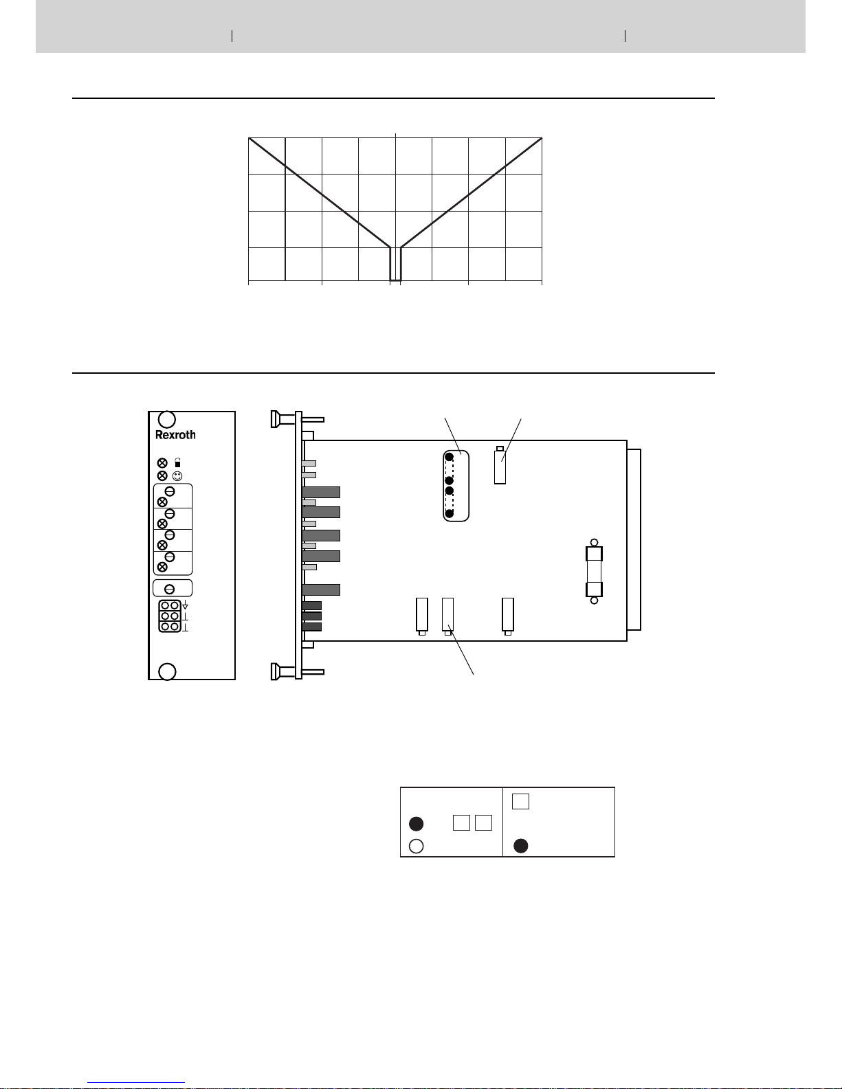
Indicator / Adjustment elements
Max. ramp time-
approx. 1 s or 5 s
Biasing current-
solenoid „A“
Biasing current
solenoid „B“
LED lamps:
H1 Call-up command value 1
H2 Call-up command value 2
H3 Call-up command value 3
H4 Call-up command value 4
H11 Operating voltage „Power on“ (yellow)
H12 Indication „Ready for operation“ (green)
Potentiometer:
w1 Command value 1
w2 Command value 2
w3 Command value 3
w4 Command value 4
t1 Ramp time
Measuring sockets:
WCommand value solenoid current
IAActual current value solenoid „A“
IBActual current value solenoid „B“
Meaning of the jumpers on the card for the settings
Meaning of the jumpers on the card for the settings
Note:
The loss of unused jumpers can be avoided by plugging
these jumpers into only one pin.
jumper plugged in
Jumper open
delivery condition
Rampenzeit

2
100
165
182
89
7
8TE (40,3)
3HE (128,4)
t
W
I
B
I
A
0 ... ± 6 V
mV = mA
mV = mA
VT 30XX
w1
H1
w2
H2
w3
H3
w4
H4
H11
H12
Hydraulics Bosch Rexroth AGRE 29935/10.12 VT 3000 7/8
Unit dimensions (Dimensions in mm)
Engineering notes / maintenance instructions / supplementary information
– The amplifier card may only be plugged in or unpluged when switched off.
– Do not use plugs with free wheel diodes or LED displays when connecting the solenoids.
– Only carry out measurements on the cards with instruments Ri > 100 kΩ.
– Measuring zero (M0) is raised by +9 V compared to 0V operating voltage and is not potentially separated, i.e. –9 V
controlled voltage is equivalent to 0V operating voltage. Therefore do not connect measuring zero (M0) to 0V operating
voltage.
– When switching command values use relays with gold contacts (small voltages, small currents).
– When switching card relays only use contacts with a loadability of approx. 40 V, 50 mA.
When controlling externally the control voltage may have a maximum residual ripple of 10 %.
– Always screen command value lines; connect screen to 0 V operating voltage on the card side, other side remains open
(danger of earth loops).
Recommendation: Also screen solenoid lines.
Use cable type LiYCY 1.5 mm2 for solenoid lines of up to 50 m in length.
For longer lengths please consult us.
– Minimum distance to arial lines, radio sources and radar equipment must be at least 1m.
– Do not lay solenoid and signal lines near power lines.
– Because of the loading current of the smoothing capacitor on the card pilot fuses must be slow.
– Note: When using the differential input both inputs must always be switched on or off simultaneously.

Bosch Rexroth AG
Hydraulics
Zum Eisengießer 1
97816 Lohr am Main, Germany
Phone +49 (0) 93 52 / 18-0
www.boschrexroth.de
© This document, as well as the data, specifications and other informa-
tion set forth in it, are the exclusive property of Bosch Rexroth AG. It
may not be reproduced or given to third parties without its consent.
The data specified above only serve to describe the product. No
statements concerning a certain condition or suitability for a certain
application can be derived from our information. The information given
does not
release the user from the obligation of own judgment and verification. It
must be remembered that our products are subject to a natural process
of wear and aging.
8/8 Bosch Rexroth AG Hydraulics VT 3000 RE 29935/10.12
Notes
Table of contents


