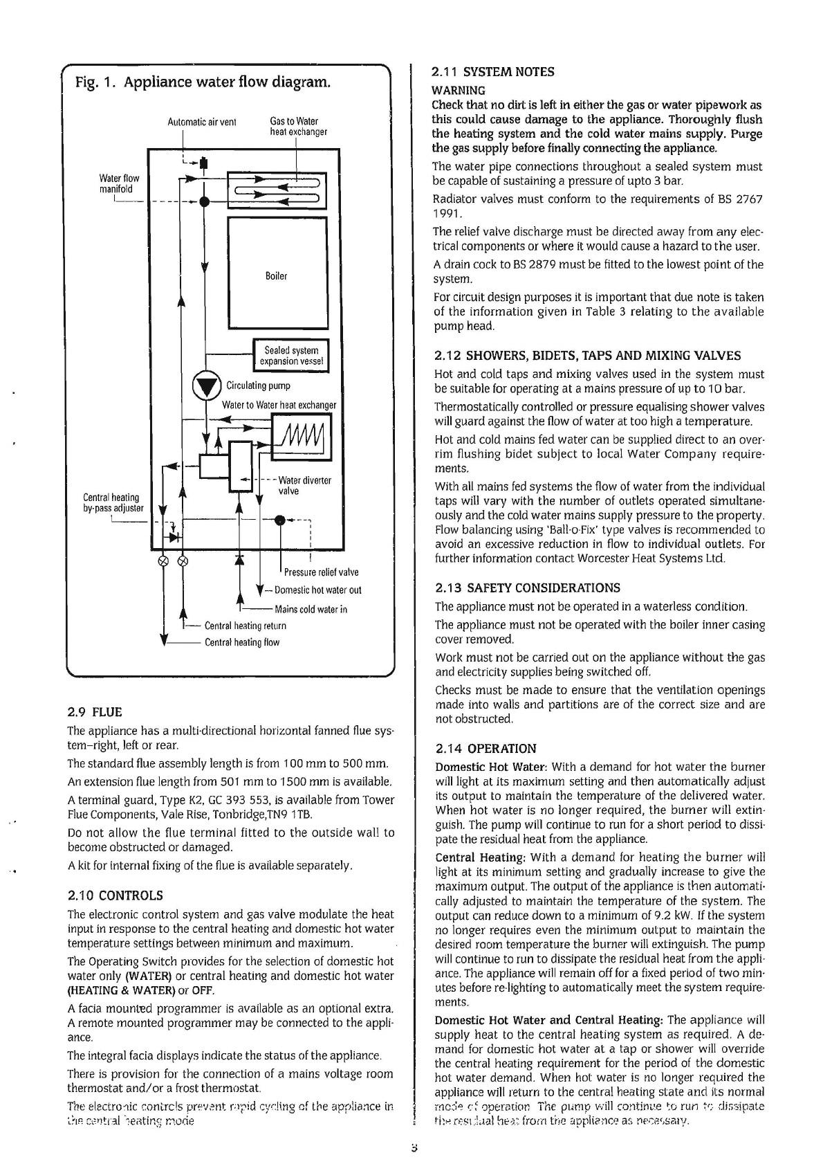
Fig.
1. Appliance
water
flow diagram.
Waterflow
manifold
I__
Central
heating
by-pass
adjuster
L__
Automatic
air
vent
Gas
to
Water
I h h
eat
axe
anger
~a-·
~
----
--
Boiler
J
Sealed
system
expansion
vessel
~
Circulating
pump
Water
to
Water
heat
exchanger
-
'l!..---
JVvV\1
~
1-c
--
---Waterdivertor
,__
valve
' -
1--0---~
-
-,.
f-*
'
'
I
o
c9
I
Pressure
relief
val
ve
-
Domestic
hot
water
out
I'
__
Mains
cold
water
in
-
Central
heating
retmn
--
Central
heatin
flow
2.9
FLUE
The
appliance has a multi-directional horizontal fanned
flue
sys-
tem-right,
left
or
rear.
The
standard
flue
assembly length
is
from
1
00
mm
to
500
mm.
An
extension
flue
length
from
501
mm
to
1500
mm
is
available.
Aterminal guard,
Type
K2,
GC
393
553,
is
available
from
Tower
Flue
Components,
Vale
Rise,
Tonbridge,TN9
1
TB.
Do
not
al.low
the
flue
terminal fitted to the outside wall to
become
obstructed or damaged.
A
kit
for
internal
fixing
of
the
flue
is
available separately.
2.1
0
CONTROLS
The
electronic control system and gas valve modulate the heat
input
in
response to the central heating and domestic hot water
temperature settings between minimum and maximum.
The
Operating
Switch
provides
for
the selection
of
domestic hot
water
only
(WATER)
or central heating and domestic hot water
(HEATING
&
WATER)
or
OFF.
A
facia
mounted programmer
is
available as
an
optional extra.
Aremote mounted programmer may
be
connected
to
the
appli-
ance.
The
integral
facia
displays indicate the status
of
the appliance.
There
is
provision
for
the connection
of
a mains voltage
room
thermostat
and/
or a frost thermostat.
The
electro'lic contrcls
prfv~~nt
nrid
cyr:!ing
cf the
applia:1ce
in
·,~IR
Cc'YJ~t.:tl
·,ei{tir.5.i
/.!.ode
2_11
SYSTEM
NOTES
WARNING
Check
that no dirt
is
left in either the gas or water pipework as
this could cause damage to the appliance. Thoroughly flush
the heating system and
the
cold water mains supply. Purge
the gas supply before finally connecting the appliance.
The
water pipe connections throughout a sealed system must
be capable
of
sustaining a pressure
of
upto 3 bar.
Radiator valves must conform to the requirements
of
BS
2767
1991.
The
relief
valve discharge must be directed away
from
any
elec·
trical
components or where
it
would cause a hazard
to
the user.
Adrain
cock
to
BS
2879 must
be
fitted
to
the lowest point
of
the
system.
For
circuit design purposes
it
is
important that due note
is
taken
of
the information given
in
Table 3 relating
to
the available
pump head.
2.12
SHOWERS,
BIDETS,
TAPS
AND
MIXING
VALVES
Hot
and
cold
taps and
mixing
valves used
in
the
system must
be suitable
for
operating at a mains pressure
of
up
to
10 bar.
Thermostatically controlled
or
pressure equalising shower valves
will
guard against the
flow
of
water at too high a temperature.
Hot
and
cold
mains
fed
water can
be
supplied direct
to
an over·
rim
flushing bidet subject to local Water Company require-
ments.
With
all
mains
fed
systems the
flow
of
water
from
the individual
taps
will
vary with the number
of
outlets operated simultane-
ously and the
cold
water mains supply pressure
to
the property.
Flow
balancing using
'Ball-o-Fix'
type valves
is
recommended to
avoid an excessive reduction
in
flow
to individual outlets.
For
further information contact Worcester Heat Systems
Ltd.
2.13
SAFETY
CONSIDERATIONS
The
appliance must not be operated
in
a waterless condition.
The
appliance must not
be
operated with the boiler inner casing
cover removed.
Work
must not
be
carried out
on
the appliance without the gas
and electricity supplies being switched
off.
Checks
must
be
made to ensure that the ventilation openings
made into
walls
and partitions are
of
the correct
size
and are
not obstructed.
2.14
OPERATION
Domestic Hot Water:
With
a demand
for
hot water the burner
will
light
at its maximum setting and then automatically adjust
its output
to
maintain the temperature
of
the delivered water.
When
hot water
is
no
longer required, the burner
will
extin·
guish.
The
pump
will
continue to
run
for
a short period to
dissi-
pate the residual heat
from
the
appliance.
Central Heating: With a demand
for
heating the burner
will
light
at its minimum setting and gradually increase
to
give
the
maximum output.
The
output of the appliance
is
then automati·
cally
adjusted
to
maintain the temperature
of
the system.
The
output can reduce down to a minimum
of
9.2
kW.
If
the system
no
longer requires even the minimum output
to
maintain the
desired room temperature the burner
will
extinguish.
The
pump
will
continue to run to dissipate the residual heat
from
the appli·
ance.
The
appliance
will
remain
off
for
a
fixed
period
of
two
min·
utes before
re-lighting
to
automatically meet the system require·
ments.
Domestic Hot Water
and
Central Heating:
The
appliance
will
supply heat
to
the central heating system as required. A
de·
mand
for
domestic hot water
at
a tap
or
shower
will
override
the central heating requirement
for
the period
of
the domestic
hot water demand.
When
hot
water
is
no
longer required the
appliance
will
return
to
the central heating state and its normal
mc3~
('~
0pennior.
The
pump will
continv.e
~o
run
~r:.
dissipate
ti:.;
r•'SLLBll'lr:J:
from
the
applii?.no~
as
ne·~B',scuv.


 Installation and maintenance instructions")