Bosch DECT6000 User manual

DECT6000 System
Installation Instructions
en


CONTENTS
1 About this manual 1
2 General information 2
3 Installation of a complete new DECT6000 system 3
3.1 Tools 3
3.2 Introduction 3
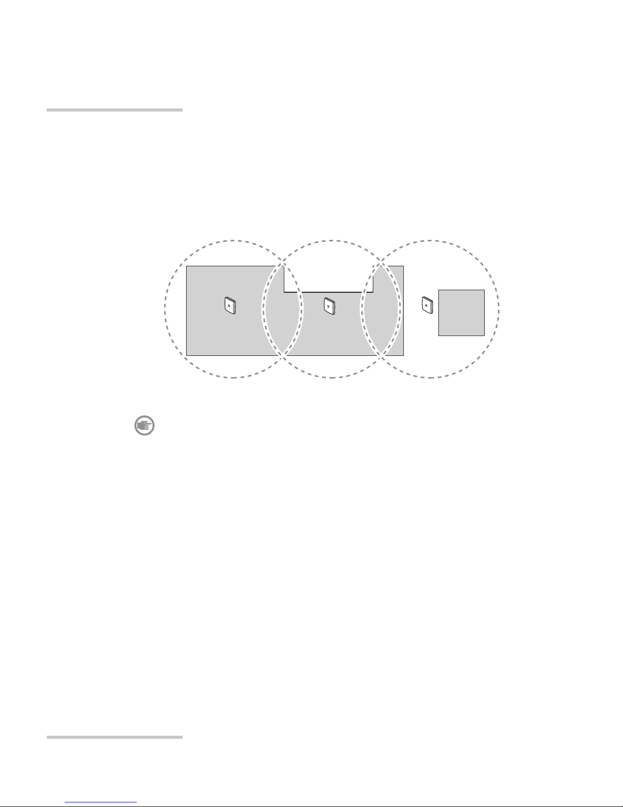
3.3 Location and number of base stations 4
3.4 Location of the DCU 4
3.5 Configuration of the DCU 5
4 DECT6000 Control Unit (DCU) LBB 6721/00 6
4.1 Functional description 6
4.2 Controls and connectors 7
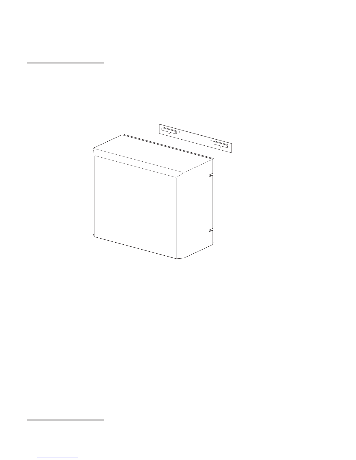
4.3 Installation 8
4.3.1 Mounting procedure 8
4.3.2 Hardware configuration of the DCU 8
4.3.3 Installing an ACU 8
4.3.4 Installing an extension card 8
4.3.5 Wiring 9
4.3.6 Software configuration of the DCU 9
5 Alphadesk central control PC 10
5.1 Functional description 10
5.2 Installation 11
5.2.1 Wiring the Alphadesk PC to the DCU
distance less than 3 m. 11
5.2.2 Wiring the Alphadesk PC to the DCU when
distance longer than 3 m. 12
6 Installing an Analogue Connection Unit (ACU)
LBB 6725/xx and LBB 6726/xx 13
6.1 Functional description 13
6.2 Connectors 14
6.3 Installation 15
6.3.1 Installing an ACU card into a DCU 15
6.3.2 Wiring ACU-PABX 17
6.3.3 Software configuration of the ACU 18
7 Base Station (BS) LBB 6730/01 19
7.1 Functional description 19
7.2 Connectors 20
7.3 Installation 21
7.3.1 Mounting procedure 21
7.3.2 Wiring 22
7.3.3 Software configuration of the base station 23
CONTENTS
en
Installation Instructions
DECT6000 T-1
9922 141 80271 03-07

8 Installing an extension card LBB 6723/00 24
8.1 Functional description 24
8.2 Connectors 24
8.3 Installation 25
8.3.1 Mounting an extension card into a DCU 25
8.3.2 Connecting base station-extension card 27
8.3.3 Software configuration of the extension card 28
9 Repeater LBB 6734/01 (Euro) and LBB 6734/11 (UK) 29
9.1 Functional description 29
9.2 Controls and connectors 30
9.3 Installation 31
9.3.1 Mounting procedure 31
9.3.2 Wiring 32
9.3.3 Technical data of the power supply 32
9.3.4 Configuration repeater 33
9.4 Directional antenna LBB 6735/00 34
9.4.1 Functional description 34
9.4.2 Connectors 34
9.4.3 Installation 35
10 Link card package LBB 6722/00 36
10.1 Functional description 36
10.2 Connectors 37
10.3 Installation 38
10.3.1 Mounting procedure 38
10.3.2 Wiring 40
10.3.3 Configuring the linked system 41
CONTENTS
Installation Instructions
T-2 DECT6000
9922 141 80271 03-07
en

1About this manual
This manual is intended to be used by installers involved in installation and
extension of DECT6000 systems. It provides information about determining layout,
installation and configuration of a DECT6000 system. Refer to the data sheet for the
latest product data.
Abbreviations
ACU Analogue Connection Unit, LBB 6725/xx and LBB 6726/xx
BS Base Station, LBB 6730/01
DCU DECT6000 Control Unit, LBB 6721/00
DECT Digital Enhanced Cordless Telecommunications
ESD Electro Static Discharge
PABX Private Automatic Branch Exchange
PCB Printed Circuit Board
PSTN Public Switched Telephone Network
RF Radio Frequency
UTP Unshielded Twisted Pair
CHAPTER 1
Installation Instructions
DECT6000 1
9922 141 80271 03-07
en

2General information
The DECT6000 system is a communication system in which cordless telephony, paging
and personal security functions are combined. Because the DECT6000 system is a
modular system it can be used in small buildings as well as large industrial sites.
The flexibility of the DECT6000 system makes it possible to connect external systems,
e.g. a nurse call system, a fire alarm system or a building management system.
The DECT6000 system main parts are:
An Alphadesk central control PC
A DECT6000 Control Unit (DCU) LBB 6721/00
Base Stations (BS) LBB 6730/01
Repeater(s) (optional) LBB 6734/01 (Euro) and LBB 6734/11 (UK)
DECT6000 handsets LBB 670x/00
The Alphadesk central control PC controls paging calls within the DECT6000 system.
The DCU is connected to the telephone exchange (PABX) to make telephone calls
possible. Traffic channels for paging and telephone calls are controlled by the DCU.
CHAPTER 2
Installation Instructions
2DECT6000
9922 141 80271 03-07
en
6
Public
Switched
Telephone
Network
Alphadesk
central control
PC
DECT6000
control unit
(DCU)
DECT6000 (PS)
Handsets
BS
BS
BS
R
RS232
PABX
2
3
4
5
6
1
Figure 2.1 Overview of the DECT6000 system

3Installation of a complete new DECT6000 system
3.1 Tools
For installation of a DECT6000 system some tools are needed. An overview of necessary
and useful tools is given below:
•Set of normal and Pozidrive screwdrivers
•Drill with drill bit (6 mm) (for mounting DCU and Base Stations)
•Crimping tool for modular plug RJ11
•Soldering iron & solder
•Tweezers (curved)
3.2 Introduction
To set up a new DECT6000 system actions mentioned in this section have to be carried
out. When an existing system must be extended some of these actions may not be
necessary, e.g. position and mounting of the DCU.
The actions that have to be carried out to install a complete system are:
• Determine position and number of base stations (and repeaters) using the
DECT 6000 deployment kit
• Mounting base stations (and repeaters)
• Determine position of the DCU
•Hardware configuration of the DCU
•Mounting the DCU
•Installing the Alphadesk central control PC with the necessary software installed
(LBB 6511/00)
•Connect the DCU, base stations, Alphadesk PC and PABX to each other
•Cable delay measurement using Alphadesk LBB 6511/00 software
•Install a back-up power supply (optional)
•Configure the complete system by using the software LBB 6511/00
CHAPTER 3
Installation Instructions
DECT6000 3
9922 141 80271 03-07
en

3.3 Location and number of base stations
Before base stations are mounted within the facility it is necessary to determine their
quantity and location. To calculate this you must take into account that the coverage
area of base stations depends on construction and layout of the facility. The average
coverage area within buildings has a radius of 30-75 metres depending on building
material. Use the DECT6000 deployment kit LBB 6738/00 to determine the base
station locations.
Note
In case the entire area cannot be covered, (e.g. A remote area which
cannot be linked to the system with a cable) you can use repeaters to
extend the coverage area. For information about repeaters see chapter 9.
3.4 Location of the DCU
The location of the DCU depends on the location of the PABX and base stations in
order to minimise cable length. The Alphadesk central control PC has to be placed close
to the DCU, because the maximum cable length between Alphadesk central control PC
and the DCU is normally 3 metres. For a longer distance refer to chapter 5.2.2.
CHAPTER 3
Installation Instructions
4DECT6000
9922 141 80271 03-07
en
BS BS BS
Figure 3.1 Example of top view with positions of base stations

3.5 Configuration of the DCU
The configuration of the DCU depends on the number of needed base stations and
handsets within the DECT6000 system, which is determined by the coverage test.
A standard DCU can connect up to 8 base stations. Expansion of the system is possible
by installing an extension card into the DCU and/or linking two DCUs to each other
(linked system, see chapter 10). Possible configurations are shown below in table 3.1.
The DCU has one or more (max. 8) Analogue Connection Units (ACU) because each
handset needs also a connection with the PABX to make a telephone call.
Note
The maximum distance between two DCUs is determined by the cable
length of the link cable, which is 1 metre.
CHAPTER 3
Installation Instructions
DECT6000 5
9922 141 80271 03-07
en
DCU configuration Maximum number
of base stations
Maximum number
of ACUs
Maximum number
of handsets
(ACU x 8)
1 DCU 8 8 64
1 DCU + extension card 16 8 64
2 DCUs (linked system) 16 16 128
2 DCUs (linked system) +
1 extension card
24 16 128
2 DCUs (linked system) +
2 extension cards
32 16 128
Table 3.1 DCU Configurations

4DECT6000 Control Unit (DCU) LBB 6721/00
4.1 Functional description
The DECT6000 Control Unit (DCU) is the heart of the DECT6000 system and is
delivered without an ACU.
The functions of the DCU are:
•Controlling the base stations
•Powering the base stations
•Establishing the connection between the handsets and the PABX analogue lines
•Providing 2-way paging in combination with the Alphadesk central control PC
CHAPTER 4
Installation Instructions
6DECT6000
9922 141 80271 03-07
en
Figure 4.1 DCU with mounting bracket

4.2 Controls and connectors
RS232 connector for connection with Alphadesk central control PC
Mains inlet, 110...230 Vac/50..60 Hz, 1.6A
Fuse, T3.15 Ah/250 Vac
On/Off switch
Reset switch
Connector (not used)
Trimmer for clock adjustment WARNING do not adjust, factory set
Battery for clock, estimated life time 10 years
Connector for (optional) extension card
Base station interconnection PCB
RS232 interconnection PCB
Jumper 1 (reset)
Jumper 2 (master/slave), for settings see chapter 10
CHAPTER 4
Installation Instructions
DECT6000 7
9922 141 80271 03-07
en
1 2 43
Link card
not used
not used
ACU 7
ACU 6
ACU 5
ACU 4
ACU 3
ACU 2
ACU 1
ACU 0
BS 0-7
BS 8-15
Figure 4.2 Bottom view of the DCU
BS 8-15 (optional)
Power
Supply
BS 0-7
1
7
J2
J1
5
234
6
RS232
Link card
not used
not used
ACU 7
ACU 6
ACU 5
ACU 4
ACU 3
ACU 2
ACU 1
ACU 0
Figure 4.3 Inside view of the DCU

4.3 Installation
4.3.1 Mounting procedure
The DCU can be used as a tabletop or can be mounted on a wall.
To mount a DCU to a wall the following steps have to be carried out:
1. Mark the drill spots on the wall. Use the bracket as drawing mould.
2. Drill 4 holes of 6 mm on the marked drill spots.
3. Place the plugs in the holes.
4. Mount the bracket to the wall using four screws.
5. Place the DCU on the bracket.
4.3.2 Hardware configuration of the DCU
The hardware configuration of the DCU depends on the number of handsets and base
stations that are used in the system.
4.3.3 Installing an ACU
The DCU must be equipped with at least one and maximum 8 ACUs to communicate
with the PABX.
For information about how to install an ACU see chapter 6.
4.3.4 Installing an extension card
The DCU can be equipped with an extension card to connect 8 extra base stations.
For information about how to install an extension card see chapter 8.
CHAPTER 4
Installation Instructions
8DECT6000
9922 141 80271 03-07
en
DCU configuration Maximum number
of base stations
Maximum number
of ACUs
Maximum number
of handsets
(ACU x 8)
1 DCU 8 8 64
1 DCU + extension card 16 8 64
2 DCUs (linked system) 16 16 128
2 DCUs (linked system) +
1 extension card
24 16 128
2 DCUs (linked system) +
2 extension cards
32 16 128
Table 4.1 DCU configurations

4.3.5 Wiring
After the DCU is equipped with one or more ACUs and an extension card (optional)
it must be connected to the base stations, PABX and Alphadesk central control PC.
For information about how to connect them to the DCU refer to the documentation
of the relevant item.
4.3.6 Software configuration of the DCU
Note
After installing and wiring the DCU the software configuration has to take
place. This has to be done by use of the software installed on the
Alphadesk central control PC, described in the “Instructions For Use” of
the LBB 6511/00.
CHAPTER 4
Installation Instructions
DECT6000 9
9922 141 80271 03-07
en

5Alphadesk central control PC
5.1 Functional description
The Alphadesk central control PC is basically installed with the LBB 6000/00 and
LBB 6511/00 software, which is the minimum configuration. The features of the
LBB 6000/00 software packages are shown below. For information to configure the
Alphadesk central control PC refer to the “Instructions For Use” of the LBB 6511/00.
Features of the basic software package LBB 6511/00
•Integrates the DECT6000 system with DP 6000 paging
•Provides paging features to DECT6000 systems
•Configuration of DECT6000 control unit (DCU)
•Subscription of DECT6000 handsets
•Transmission of normal, urgent, emergency and mailbox messages
• Reception of paging message results
• Enables handset-to-handset messaging
CHAPTER 5
Installation Instructions
10 DECT6000
9922 141 80271 03-07
en

5.2 Installation
5.2.1 Wiring the Alphadesk PC to the DCU distance less than 3 m.
The Alphadesk central control PC is connected to the RS232 connector (see Figure 5.1)
of the DCU with an RS232 cable. Normally this cable is equipped with two 9-pole
connectors. Some PCs however are equipped with a 25-pole RS232 connection.
The cable layout for both connections is given in Figure 5.2.
RS232 connector for connection with Alphadesk central control PC
Mains inlet, 110...230 Vac/50..60 Hz, 1.6A
Fuse, T3.15 Ah/250 Vac
On/Off switch
Note
The maximum length of the RS232 cable is 3 metres.
CHAPTER 5
Installation Instructions
DECT6000 11
9922 141 80271 03-07
en
1 2 43
Link card
not used
not used
ACU 7
ACU 6
ACU 5
ACU 4
ACU 3
ACU 2
ACU 1
ACU 0
BS 0-7
BS 8-15
Figure 5.1 Bottom view of the DCU
DCU Alphadesk central control PC
9-pole D
connector
female
9-pole D
connector
female
Pin
1
2
3
4
5
6
7
8
Pin
1
2
3
4
5
6
7
8
9
DCD
RxD
TxD
DTR
GND
DSR
RTS
CTS
8
3
2
20
7
6
4
5
PinDescription
DCD
RxD
TxD
DTR
GND
DSR
RTS
CTS
Not connected
Description
or
25-pole D
connector
female
Figure 5.2 RS232 9-pole female to 9- or 25-pole female

5.2.2 Wiring the Alphadesk PC to the DCU when distance
longer than 3 m.
In case the distance between the Alphadesk central control PC and the DCU is longer
than 3 metres, you have to use a modem or RS485 converter.
CHAPTER 5
Installation Instructions
12 DECT6000
9922 141 80271 03-07
en

6Installing an Analogue Connection Unit (ACU)
LBB 6725/xx and LBB 6726/xx
6.1 Functional description
The Analogue Connection Unit (ACU), which is mounted in the DCU, is an interface
unit between the DCU and the telephone exchange (PABX) analogue lines.
Each ACU contains 8 analogue lines in which each line represents a DECT6000
handset. The ACU also functions as a galvanic isolation between the DECT6000 system
and the PABX. One DCU can contain up to 8 ACUs. Figure 6.1 and 6.2 shows the
situation without and with the use of a DCU. If possible existing telephone wiring may
be used as shown in example below.
CHAPTER 6
Installation Instructions
DECT6000 13
9922 141 80271 03-07
en
PABX
Terminal strip Terminal strip
Figure 6.1 Normal telephone system
PABX
DCU
Terminal strip Terminal strip
BS BS
BS-DCU connection cable
ACU-PABX connection cable
BS BS
Figure 6.2 Telephone system integrated with DECT using existing cabling

Note
On the type of PABX which is used, choose an ACU with loop break circuit
LBB 6725 or an ACU with earth circuit LBB 6726.
6.2 Connectors
DCU slot connector
PABX connector 25 pole male. For connections see chapter 6.3.2
CHAPTER 6
Installation Instructions
14 DECT6000
9922 141 80271 03-07
en
Type number Country code Country
LBB 6725 or LBB 6726 /00 Most countries except;
LBB 6725 /10 France
LBB 6725 or LBB 6726 /20 The Netherlands
LBB 6725 or LBB 6726 /30 South Africa
LBB 6725 or LBB 6726 /40 Poland
Table 6.1 Available types of ACU
2
1
Figure 6.3 Connectors of the ACU

6.3 Installation
6.3.1 Installing an ACU card into a DCU
To be able to install the ACU card into the DCU, proceed as follows.
Note
For more information refer to the “Installation Instructions” on
the CD-ROM delivered with the DCU
Warning
Disconnect the main power supply before any work is carried out
on the DECT6000 system.
Caution
When work is carried out on the DCU wear an anti-ESD bracelet to
prevent damage to the PCBs.
CHAPTER 6
Installation Instructions
DECT6000 15
9922 141 80271 03-07
en

1. Unscrew the 2 screws at each side of the DCU (see figure 6.4).
2. Unscrew 4 screws ‚ at the bottom of the DCU.
3. Lift the top cover from the DCU.
4. Remove blind cover of the first available slot. Blind cover plates are slightly
welded to the DCU housing, tap out a blind cover plate with a screwdriver
(see figure 6.4).
5. Place the ACU in the first available slot (ACU0…ACU7) (see figure 6.5).
6. Screw the ACU to the DCU housing with a Pozidrive size 1 screwdriver and
the two supplied screws.
7. Close the DCU.
CHAPTER 6
Installation Instructions
16 DECT6000
9922 141 80271 03-07
en
BS 0-7
BS 8-15
1 1
2
2 2
2
Link card
not used
not used
ACU 7
ACU 6
ACU 5
ACU 4
ACU 3
ACU 2
ACU 1
ACU 0
Figure 6.4 Bottom view of the DCU
Figure 6.5 Placing the ACU into the DCU
Table of contents
Other Bosch Cordless Telephone manuals