Bosch DIVAR IP 7000 1U User manual

DIVAR IP 7000 1U
DIP-7040-00N, DIP-7042-2HD, DIP-7042-4HD
en Installation Manual


Table of contents
1Safety precautions 5
1.1 General safety precautions 5
1.2 Electrical safety precautions 6
1.3 ESD precautions 7
1.4 Operating precautions 7
1.5 Important notices 8
1.6 FCC and ICES compliance 8
2System overview 9
2.1 Chassis features 9
2.2 Chassis components 9
2.2.1 Chassis 9
2.2.2 Backplane 10
2.2.3 Fans 10
2.2.4 Mounting rails 10
2.2.5 Power supply 10
2.2.6 Air shroud 10
2.3 System interface 10
2.3.1 Control panel buttons 11
2.3.2 Control panel LEDs 11
2.3.3 Power supply LEDs and overheat indicators 12
3Inserting hard disks 13
4Rack installation 14
4.1 Unpacking the system 14
4.2 Preparing for setup 14
4.2.1 Choosing a setup location 14
4.2.2 Rack precautions 14
4.2.3 General system precautions 15
4.2.4 Rack mounting considerations 15
4.3 Rack mounting instructions 16
4.3.1 Identifying the sections of the rack rails 16
4.3.2 Installing the inner rails 17
4.3.3 Assembling the outer rails 17
4.3.4 Installing the outer rails to the rack 18
4.3.5 Installing the chassis into the rack 19
4.3.6 Installing the chassis into a Telco rack 20
4.4 Turning on the system 20
5System setup - first steps 21
5.1 Introduction 21
5.2 Setup instruction 21
5.3 Starting the application 21
5.4 Using Bosch VMS Config Wizard 22
5.5 Adding additional licenses 23
5.6 Using Bosch VMS Operator Client 23
6Installing additional drives 25
6.1 Adding new drives to Windows Server 25
6.2 Creating a VHD iSCSI target for VRM 25
6.3 Adding and formatting the VHD as a VRM target 26
DIVAR IP 7000 1U Table of Contents | en 3
Bosch Sicherheitssysteme GmbH Installation Manual 2014.12 | V3 | DOC

7Connecting to the internet 27
7.1 Protecting the system from unauthorized access 27
7.2 Setting up port forwarding 27
7.3 Choosing an appropriate client 27
7.3.1 Remote connection with Operator Client 27
7.3.2 Remote connection with Video Security App 27
7.4 Installing an Enterprise Management Server 28
8Recovering the unit 29
9Additional documentation and client software 30
10 Appendices 31
10.1 Motherboard 31
10.1.1 Motherboard layout 31
10.1.2 Motherboard component overview 32
10.1.3 Motherboard features 34
10.1.4 Block diagram 36
10.2 Chipset overview 36
10.3 PC health monitoring 37
10.4 Power configuration settings 37
10.5 Power supply 38
10.6 Super I/O 38
10.7 iSCSI support 38
10.8 Overview of the Nuvoton BMC controller 39
4en | Table of Contents DIVAR IP 7000 1U
2014.12 | V3 | DOC Installation Manual Bosch Sicherheitssysteme GmbH

Safety precautions
Observe the safety precautions in this chapter.
General safety precautions
Follow these rules to ensure general safety:
– Keep the area around the system clean and free of clutter.
– Place the chassis top cover and any system components that have been removed away
from the system or on a table so that they won't accidentally be stepped on.
– While working on the system, do not wear loose clothing such as neckties and
unbuttoned shirt sleeves, which can come into contact with electrical circuits or be
pulled into a cooling fan.
– Remove any jewelry or metal objects from your body, which are excellent metal
conductors that can create short circuits and harm you if they come into contact with
printed circuit boards or areas where power is present.
– After accessing the inside of the system, close the system back up and secure it to the
rack unit after ensuring that all connections have been made.
– The system is heavy when fully loaded. When lifting the system, two people at either end
should lift slowly with their feet spread out to distribute the weight. Always keep your
back straight and lift with your legs.
!
Warning!
Interruption of mains supply:
Voltage is applied as soon as the mains plug is inserted into the mains socket.
However, for devices with a mains switch, the device is only ready for operation when the
mains switch (ON/OFF) is in the ON position. When the mains plug is pulled out of the
socket, the supply of power to the device is completely interrupted.
!
Warning!
Removing the housing:
To avoid electric shock, the housing must only be removed by qualified service personnel.
Before removing the housing, the plug must always be removed from the mains socket and
remain disconnected while the housing is removed. Servicing must only be carried out by
qualified service personnel. The user must not carry out any repairs.
!
Warning!
Power cable and AC adapter:
When installing the product, use the provided or designated connection cables, power cables
and AC adaptors. Using any other cables and adaptors could cause a malfunction or a fire.
Electrical Appliance and Material Safety Law prohibits the use of UL or CSA-certified cables
(that have UL/CSA shown on the code) for any other electrical devices.
1
1.1
DIVAR IP 7000 1U Safety precautions | en 5
Bosch Sicherheitssysteme GmbH Installation Manual 2014.12 | V3 | DOC

!
Warning!
Lithium battery:
Batteries that have been inserted wrongly can cause an explosion. Always replace empty
batteries with batteries of the same type or a similar type recommended by the manufacturer.
Handle used batteries carefully. Do not damage the battery in any way. A damaged battery
may release hazardous materials into the environment.
Dispose of empty batteries according to the manufacturer's instructions.
!
Warning!
Handling of lead solder materials used in this product may expose you to lead, a chemical
known to the State of California to cause birth defects and other reproductive harm.
Notice!
Electrostatically sensitive device:
To avoid electrostatic discharges, the CMOS/MOSFET protection measures must be carried
out correctly.
When handling electrostatically sensitive printed circuits, grounded anti-static wrist bands
must be worn and the ESD safety precautions observed.
Notice!
Installation should only be carried out by qualified customer service personnel in accordance
with the applicable electrical regulations.
Disposal
Your Bosch product has been developed and manufactured using high-
quality materials and components that can be reused.
This symbol means that electronic and electrical devices that have reached
the end of their working life must be disposed of separately from
household waste.
In the EU, separate collecting systems are already in place for used
electrical and electronic products. Please dispose of these devices at your
local communal waste collection point or at a recycling center.
Electrical safety precautions
Basic electrical safety precautions should be followed to protect you from harm and the
system from damage:
– Be aware of the locations of the power on/off switch on the chassis as well as the room's
emergency power-off switch, disconnection switch or electrical outlet. If an electrical
accident occurs, you can then quickly remove power from the system.
– Do not work alone when working with high voltage components.
– Power should always be disconnected from the system when removing or installing main
system components, such as the motherboard or memory modules. When disconnecting
power, you should first turn off the system and then unplug the power cords from all the
power supply modules in the system.
– When working around exposed electrical circuits, another person who is familiar with the
power-off controls should be nearby to switch off the power if necessary.
1.2
6en | Safety precautions DIVAR IP 7000 1U
2014.12 | V3 | DOC Installation Manual Bosch Sicherheitssysteme GmbH

– Use only one hand when working with powered-on electrical equipment. This is to avoid
making a complete circuit, which will cause electrical shock. Use extreme caution when
using metal tools, which can easily damage any electrical components or circuit boards
they come into contact with.
– The power supply power cords must include a grounding plug and must be plugged into
grounded electrical outlets. The unit has more than one power supply cord. Disconnect
both power supply cords before servicing to avoid electrical shock.
– Mainboard replaceable soldered-in fuses: Self-resetting PTC (Positive Temperature
Coefficient) fuses on the mainboard must be replaced by trained service technicians only.
The new fuse must be the same or equivalent as the one replaced. Contact technical
support for details and support.
!
Caution!
Mainboard Battery: There is a danger of explosion if the onboard battery is installed upside
down, which will reverse its polarities. This battery must be replaced only with the same or
an equivalent type recommended by the manufacturer (CR2032). Dispose of used batteries
according to the manufacturer's instructions.
!
Caution!
DVD-ROM Laser: This system comes without a DVD-ROM drive but if added: To prevent direct
exposure to the laser beam and hazardous radiation exposure, do not open the enclosure or
use the unit in any unconventional way.
ESD precautions
Electrostatic Discharge (ESD) is generated by two objects with different electrical charges
coming into contact with each other. An electrical discharge is created to neutralize this
difference, which can damage electronic components and printed circuit boards. The
following measures are generally sufficient to neutralize this difference before contact is made
to protect your equipment from ESD:
– Do not use mats designed to decrease electrostatic discharge as protection from
electrical shock. Instead, use rubber mats that have been specifically designed as
electrical insulators.
– Use a grounded wrist strap designed to prevent static discharge.
– Keep all components and printed circuit boards (PCBs) in their antistatic bags until ready
for use.
– Touch a grounded metal object before removing the board from the antistatic bag.
– Do not let components or printed circuit boards come into contact with your clothing,
which may retain a charge even if you are wearing a wrist strap.
– Handle a board by its edges only. Do not touch its components, peripheral chips, memory
modules or contacts.
– When handling chips or modules, avoid touching their pins.
– Put the mainboard and peripherals back into their antistatic bags when not in use.
– For grounding purposes, make sure your computer chassis provides excellent
conductivity between the power supply, the case, the mounting fasteners and the
mainboard.
Operating precautions
The chassis cover must be in place when the system is operating to assure proper cooling. Out
of warranty damage to the system can occur if this practice is not strictly followed.
1.3
1.4
DIVAR IP 7000 1U Safety precautions | en 7
Bosch Sicherheitssysteme GmbH Installation Manual 2014.12 | V3 | DOC

Note:
Please handle used batteries carefully. Do not damage the battery in any way. A damaged
battery may release hazardous materials into the environment. Do not discard a used battery
in the garbage or a public landfill. Please comply with the regulations set up by your local
hazardous waste management agency to dispose of your used battery properly.
Important notices
Accessories - Do not place this unit on an unstable stand, tripod, bracket,
or mount. The unit may fall, causing serious injury and/or serious damage to
the unit. Use only with the cart, stand, tripod, bracket, or table specified by
the manufacturer. When a cart is used, use caution and care when moving
the cart/apparatus combination to avoid injury from tip-over. Quick stops,
excessive force, or uneven surfaces may cause the cart/unit combination to
overturn. Mount the unit per the manufacturer's instructions.
FCC and ICES compliance
(only for U.S.A. and Canada)
This equipment has been tested and found to comply with the limits for a Class A digital
device pursuant to Part 15 of the FCC Rules. These limits are designed to provide reasonable
protection against harmful interference when the equipment is operated in a commercial
environment. This equipment generates, uses, and can radiate radio frequency energy and, if
not installed and used in accordance with the manufacturer’s instruction manual, may cause
harmful interference with radio communications. Operation of this equipment in a residential
area is likely to cause harmful interference, in which case you will be required to correct the
interference at your own expense.
1.5
1.6
8en | Safety precautions DIVAR IP 7000 1U
2014.12 | V3 | DOC Installation Manual Bosch Sicherheitssysteme GmbH

System overview
DIVAR IP 7000 1U is an affordable, simple and reliable all-in-one recording, viewing and
management solution for network surveillance systems of up to 64 channels (with 32 channels
pre-licensed). Running the full Bosch VMS (Video Management System) solution and powered
by Bosch VRM (Video Recording Manager) software, the DIVAR IP 7000 1U is an intelligent IP
storage device that eliminates the need for separate NVR (Network Video Recorder) server and
storage hardware.
The 1U unit combines advanced management and state-of-the-art recording management into
a single cost-effective, plug and play IP recording appliance for IT-minded customers which are
seeking for a state-of-the-art “second generation” NVR recording solution.
DIVAR IP 7000 1U features:
– Instant real time access to video
View high quality HD video despite low or limited bandwidth connections. Dynamic
Transcoding technology ensures that you can view your video immediately — anytime,
anywhere.
– Easy installation
DIVAR IP 7000 1U features wizard based set-up and centralized configuration to reduce
installation times. All components are pre-installed and pre-configured. Simply connect to
the network and turn on the unit — DIVAR IP 7000 1U starts recording straight out of the
box.
– Access to Bosch VMS
After starting the system, immediate access to the Bosch VMS management application is
offered by a customized user interface. The ability to use one central user interface for
configuration and operation management reduces installation and training requirements,
and helps to keep ongoing system management costs low.
Chassis features
The chassis includes the following features:
– 4 slots for 4 SATA drives
– Graphic card (1x DVI, 1x Display Port output)
– One slim DVD-RW drive. This drive allows you to quickly install or save data.
– One internal USB Transcoder device
– Other onboard features are included to promote system health. These include various
cooling fans, a convenient power switch and a reset button.
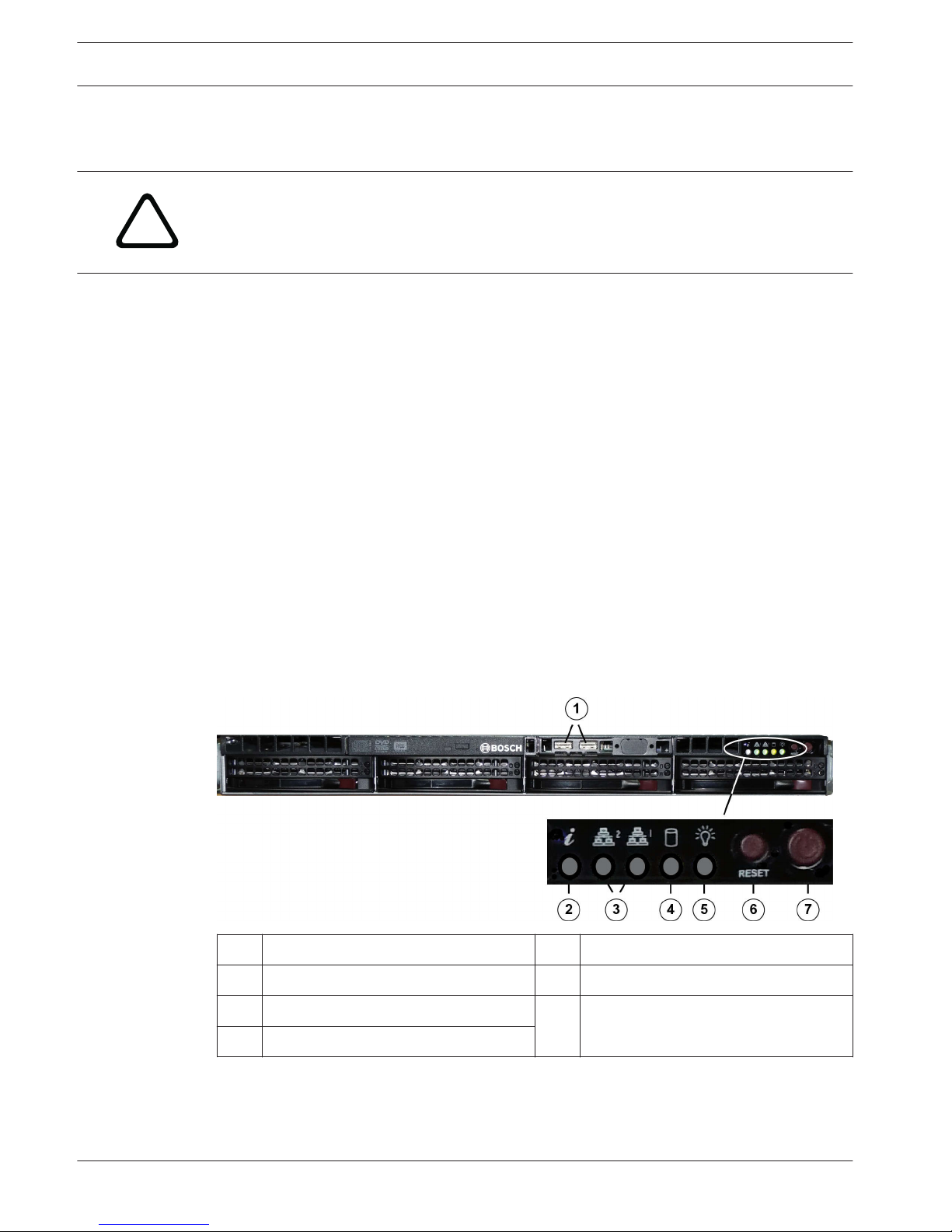
Chassis components
This chapter describes the most common components included with your chassis. For more
information, see the installation instructions detailed later in this manual.
Chassis
The chassis includes 4 hard drive bays and supports a 1U backplane, fans and two power
supplies.
2
2.1
2.2
2.2.1
DIVAR IP 7000 1U System overview | en 9
Bosch Sicherheitssysteme GmbH Installation Manual 2014.12 | V3 | DOC

Backplane
Each chassis comes with a 1U backplane. The backplane accepts SAS/SATA hard drives.
!
Warning!
Use caution when servicing and working around the backplane. Hazardous voltage or energy
is present on the backplane when the system is operating. Do not touch the backplane with
any metal objects and make sure no ribbon cables touch the backplane.
Fans
The chassis supports system fans that are 1U high and powered from the motherboard.
Mounting rails
The unit can be placed in a rack for secure storage and use. To setup your rack, follow the
step-by-step instructions included in this manual.
Power supply
Each chassis model includes 2 high-efficiency power supplies (redundant). In the unlikely
event your power supply fails, replacement is simple and can be accomplished without tools.
Air shroud
Air shrouds are shields, usually plastic, which conduct the airflow directly to where it is
needed. Always use the air shroud included with your chassis.
System interface
There are several LEDs on the front and rear of the chassis. The LEDs show the over-all status
of the system and the activity and health of specific components.
Front view:
12x USB 2.0 5Power
2Failure information (not used) 6Reset
3NIC1/NIC2 7Power on/off
4HDD
2.2.2
2.2.3
2.2.4
2.2.5
2.2.6
2.3
10 en | System overview DIVAR IP 7000 1U
2014.12 | V3 | DOC Installation Manual Bosch Sicherheitssysteme GmbH

Rear view:
12x mains connection 100 – 240 VAC,
50 - 60 Hz
Note: Connect both power cables.
5Monitor (VGA)
Note: Do not use!
22x PS/2 (mouse and keyboard) 62x NIC
Note: Connect both NIC ports to the
appropriate network switch.
32x USB 2.0 71x graphic card (1x Display Port,
1x DVI)
Note: DVI port must be used for
configuration.
4Serial interface COM
Control panel buttons
There are two push-buttons located on the front of the chassis. These are (in order from left
to right) a reset button and a power on/off button.
– Reset: The reset button is used to reboot the system.
– Power: The main power switch is used to apply or remove power from the power
supply to the server system. Turning off system power with this button removes the main
power but keeps standby power supplied to the system. Therefore, you must unplug
system before servicing.
Control panel LEDs
The control panel located on the front of the chassis has LEDs to provide you with critical
information related to different parts of the system. This section explains what each LED
indicates.
– Information LED: not used
– NiC2: A flashing LED indicates network activity on GLAN2.
– NIC1: A flashing LED indicates network activity on GLAN1.
2.3.1
2.3.2
DIVAR IP 7000 1U System overview | en 11
Bosch Sicherheitssysteme GmbH Installation Manual 2014.12 | V3 | DOC

– HDD: A flashing LED indicates IDE channel activity in the SAS/SATA drive, SCSI
drive, and/or DVD-ROM drive activity.
– Power: Indicates power is being supplied to the system's power supply units.
This LED should normally be illuminated when the system is operating.
Power supply LEDs and overheat indicators
This chassis provides several options which may include hot-swappable, cold-swappable, and
redundant power supplies. Some power supplies include an LED in the rear with the following
definitions:
Power supply LEDs
Solid green Power supply is on.
Solid amber The power supply is plugged in and turned off, or the
system is off but in an abnormal state.
2.3.3
12 en | System overview DIVAR IP 7000 1U
2014.12 | V3 | DOC Installation Manual Bosch Sicherheitssysteme GmbH

Inserting hard disks
This chapter describes the insertion of hard disks that are mounted in drive carriers to
simplify their installation.
To insert the drive carrier:
4Insert the drive carrier into the chassis bay. Make sure that the drive carrier handle is
completely closed.
Notice!
We recommend using the respective Bosch hard disk drives. The hard disk drives as one of
the critical component are carefully selected by Bosch based on available failure rates. HDD –
not delivered from Bosch – are not supported. Information on supported HDDs can be found
in the datasheet in the Bosch Online Product Catalog.
See also:
–Installing additional drives, page 25
3
DIVAR IP 7000 1U Inserting hard disks | en 13
Bosch Sicherheitssysteme GmbH Installation Manual 2014.12 | V3 | DOC

Rack installation
This chapter provides a quick setup checklist to get your chassis up and running. Following
these steps in the order given should enable you to have the system operational within a
minimum amount of time.
Unpacking the system
You should inspect the box the chassis was shipped in and note if it was damaged in any way.
If the chassis itself shows damage, file a damage claim with the carrier who delivered it and
notify the respective Bosch RMA desk.
You will also need it placed near at least one grounded power outlet.
Due to the weight of the system: After opening the top of the shipping box, one person should
stand at either end and lift the disk array out together.
Be sure to read the safety precautions.
Preparing for setup
The box the system is shipped in includes a rack mount kit, which you will need to install the
system into the rack.
Follow the steps in the order given to complete the installation process in a minimum amount
of time. Read this section before you begin the installation procedure outlined in the sections
that follow.
Choosing a setup location
– Situate the system in a clean, dust-free area that is well ventilated. Avoid areas where
heat, electrical noise and electromagnetic fields are generated. Place the system near a
grounded power outlet.
– Leave approximately 25 inches clearance in front of the rack to be able to open the front
door completely.
– Leave approximately 30 inches of clearance in the back of the rack to allow for sufficient
airflow and ease in servicing.
– Install the system only in a Restricted Access Location (dedicated equipment rooms,
service closets and the like).
Notice!
This product is not suitable for use with visual display work place devices acccording to §2 of
the the German Ordinance for Work with Visual Display Units.
Rack precautions
!
Warning!
To prevent bodily injury when mounting or servicing this unit in a rack, you must take special
precautions to ensure that the system remains stable. The following guidelines are provided
to ensure your safety:
– Ensure that the leveling jacks on the bottom of the rack are fully extended to the floor
with the full weight of the rack resting on them.
– In single rack installations, attach stabilizers to the rack.
– If the rack is provided with stabilizing devices, install the stabilizers before mounting or
servicing the unit in the rack.
4
4.1
4.2
4.2.1
4.2.2
14 en | Rack installation DIVAR IP 7000 1U
2014.12 | V3 | DOC Installation Manual Bosch Sicherheitssysteme GmbH

– This unit should be mounted at the bottom of the rack if it is the only unit in the rack.
– When mounting this unit in a partially filled rack, load the rack from the bottom to the top
with the heaviest component at the bottom of the rack.
– In multiple rack installations, couple the racks together.
– Always make sure the rack is stable before extending a component from the rack.
– Extend only one component at a time - extending two or more simultaneously may cause
the rack to become unstable.
General system precautions
– Review the electrical and general safety precautions that came with the components you
are adding to your chassis.
– Determine the placement of each component in the rack before installing the rails.
– Install the heaviest components on the bottom of the rack first, and then work up.
– Use a regulating uninterruptible power supply (UPS) to protect the system from power
surges, voltage spikes if you want to keep your system operating in case of a power
failure.
– Allow the SATA hard drives and power supply modules to cool before touching them.
– Always keep the rack’s front door and all panels and components on the system closed
when not servicing to maintain proper cooling.
See also:
–Safety precautions, page 5
Rack mounting considerations
Ambient operating temperature
If installed in a closed or multi-unit rack assembly, the ambient operating temperature of the
rack environment may be greater than the ambient temperature of the room. Therefore,
consideration should be given to installing the equipment in an environment compatible with
the manufacturer’s maximum rated ambient temperature (Tmra).
Reduced airflow
Equipment should be mounted into a rack so that the amount of airflow required for safe
operation is not compromised.
Mechanical loading
Equipment should be mounted into a rack so that a hazardous condition does not arise due to
uneven mechanical loading.
Circuit overloading
Consideration should be given to the connection of the equipment to the power supply
circuitry and the effect that any possible overloading of circuits might have on overcurrent
protection and power supply wiring. Appropriate consideration of equipment nameplate
ratings should be used when addressing this concern.
Reliable ground
A reliable ground must be maintained at all times. To ensure this, the rack itself should be
grounded. Particular attention should be given to power supply connections other than the
direct connections to the branch circuit (i.e. the use of power strips, etc.).
4.2.3
4.2.4
DIVAR IP 7000 1U Rack installation | en 15
Bosch Sicherheitssysteme GmbH Installation Manual 2014.12 | V3 | DOC

Rack mounting instructions
This section provides information on installing the chassis into a rack unit. There are a variety
of rack units on the market, which may mean the assembly procedure will differ slightly. You
should also refer to the installation instructions that came with the rack unit you are using.
Notice!
This rail will fit a rack between 26" and 33.5" deep.
Identifying the sections of the rack rails
The chassis package includes two rail assemblies in the rack mounting kit. Each assembly
consists of two sections:
– an inner fixed chassis rail that secures directly to the chassis
– an outer fixed rack rail that secures directly to the rack itself.
1Rail extension (inner rail is pre-installed on the chassis)
2Outer rails
4.3
4.3.1
16 en | Rack installation DIVAR IP 7000 1U
2014.12 | V3 | DOC Installation Manual Bosch Sicherheitssysteme GmbH

Installing the inner rails
The chassis includes a set of inner rails which are in two sections: inner rails and inner rail
extensions. The inner rails are pre-attached and do not interfere with normal use of the
chassis if you decide not to use a server rack. Attach the inner rail extension to stabilize the
chassis within the rack.
To install the inner rails:
1. Place the inner rail extensions on the side of the chassis aligning the hooks of the chassis
with the rail extension holes. Make sure the extension faces "outward" just like the pre-
attached inner rail.
2. Slide the extension toward the front of the chassis.
3. Secure the chassis with 2 screws as illustrated.
4. Repeat steps for the other inner rail extension.
Assembling the outer rails
To assemble the outer rails:
1. Secure to the front of the rack.
2. Attach the two sections of the outer rail together.
3. Secure to the rear of the rack.
4.3.2
4.3.3
DIVAR IP 7000 1U Rack installation | en 17
Bosch Sicherheitssysteme GmbH Installation Manual 2014.12 | V3 | DOC

Installing the outer rails to the rack
Outer rails attach to the rack and hold the chassis in place. The outer rails extend between 30
inches and 33 inches.
To install the outer rails to the rack
1. Attach the longer section of the outer rail to the outside of the shorter section of the
outer rail. You must align the pins with the slides. Both ends of the outer rail must face
the same direction in order to be secured to the rack.
2. Adjust both sections of the outer rail to the proper length so that the rail fits snugly
within the rack.
3. Secure the longer section of the outer rail to the front of the rack with two M5 screws
and the shorter section to the rear side of the rack with two M5 screws.
4. Repeat steps for the remaining outer rail.
See also:
–Assembling the outer rails, page 17
4.3.4
18 en | Rack installation DIVAR IP 7000 1U
2014.12 | V3 | DOC Installation Manual Bosch Sicherheitssysteme GmbH

Installing the chassis into the rack
1Inner rail 3Outer rails
2Rail extension
To install the chassis into a rack
1. Confirm that chassis includes the inner rails and rail extensions. Also, confirm that the
outer rails are installed on the rack.
2. Line chassis rails with the front of the rack rails.
3. Slide the chassis rails into the rack rails, keeping the pressure even on both sides (you
may have to depress the locking tabs when inserting). When the system has been pushed
completely into the rack, you should hear the locking tabs click.
4. (Optional) Insert and tightening the thumbscrews that hold the front of the system to the
rack.
!
Warning!
Do not pick up the unit with the front handles. The handles are designed to pull the system
from a rack only.
!
Warning!
Stability hazard
Before sliding the unit out for servicing make sure that the rack stabilizing mechanism is in
place, or the rack is bolted to the floor. Failure to stabilize the rack can cause the rack to tip
over.
See also:
–Rack precautions, page 14
4.3.5
DIVAR IP 7000 1U Rack installation | en 19
Bosch Sicherheitssysteme GmbH Installation Manual 2014.12 | V3 | DOC

Installing the chassis into a Telco rack
To install the chassis into a Telco type rack, use two L-shaped brackets on either side of the
chassis (four in total). First, determine how far the chassis will extend out the front of the
rack. Larger chassis should be positioned to balance the weight between front and back. If a
bezel is included on the chassis, remove it. Then attach the two front brackets to each side of
the chassis, then the two rear brackets positioned with just enough space to accommodate
the width of the Telco rack. Finish by sliding the chassis into the rack and tightening the
brackets to the rack.
Turning on the system
The last thing to be done is to provide input power to the system.
To turn on the system:
1. Plug the power cord from the power supply unit into a high-quality power strip that offers
protection from electrical noise and power surges. We recommended using an
uninterruptible power supply (UPS).
2. Press the power button on the control panel to turn on the system.
4.3.6
4.4
20 en | Rack installation DIVAR IP 7000 1U
2014.12 | V3 | DOC Installation Manual Bosch Sicherheitssysteme GmbH
Table of contents
Popular Firewall manuals by other brands

Cisco
Cisco M190 quick start guide

Fortinet
Fortinet FortiGate 800/800F installation guide

PaloAlto Networks
PaloAlto Networks PA-800 SERIES Hardware reference

Ruijie Networks
Ruijie Networks RG-WALL1600-S3100 Hardware installation and reference guide

D-Link
D-Link NetDefend DFL-1660 user manual

Sophos
Sophos XG 115 quick start guide

Fortinet
Fortinet FortiGate-200A quick start guide

Sophos
Sophos UTM 425 operating instructions

IBM
IBM Proventia Management SiteProtector SP1001 Getting started

KEYTRONIX
KEYTRONIX I-SAD 19"-S operating instructions

Watchguard
Watchguard Firebox M400 quick start guide

Watchguard
Watchguard SOHO Features guide