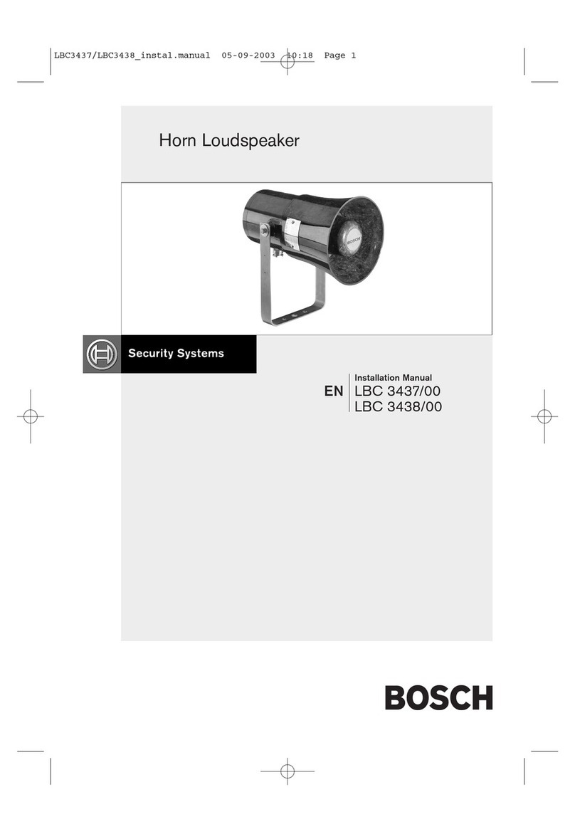
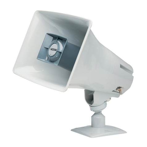
Bosch LHN-UC15L-SIP User manual

LHN‑UC15L‑SIP | LHN‑UC15W‑SIP |
AMN‑P15‑SIP
en User manual


LHN‑UC15L‑SIP | LHN‑UC15W‑SIP | AMN‑P15‑SIP Table of contents | en 3
Bosch Security Systems B.V. User manual 2023.02 | V01 | F.01U.389.835
Table of contents
1Safety 5
1.1 Safety information 5
1.2 Disposal instructions 6
1.3 FCC statement - Wired Class B digital device (unintentional radiator) 6
1.4 FCC suppliers Declaration of Conformity 7
2Installation 8
2.1 LHN-UC15L-SIP or LHN-UC15W-SIP IP Horn loudspeaker 8
2.1.1 Considerations 8
2.1.2 Mounting 8
2.1.3 Connections 9
2.1.4 Microphone 12
2.1.5 Physical reset button 13
2.2 AMN-P15-SIP IP Amplifier Module 14
2.2.1 Considerations 14
2.2.2 Mounting 14
2.2.3 Connections 17
2.2.4 Physical reset button 20
3Getting started 21
3.1 Download and update firmware 21
3.2 IP address detection 22
3.3 Logon with the web browser 23
4Web-GUI configuration 24
4.1 Overview 24
4.2 Generic settings 25
4.3 Users 25
4.4 SIP 26
4.4.1 SIP settings 26
4.4.2 SIP accounts 26
4.5 Audio 28
4.5.1 Basic audio settings 29
4.5.2 Advanced audio settings 30
4.6 Messages 31
4.7 Rules 31
4.7.1 Name and priority 32
4.7.2 Trigger settings 32
4.7.3 Action settings 34
4.8 Certificates 36
4.9 Security 36
4.10 Maintenance 37
4.10.1 Device tests 37
4.10.2 User interface settings 38
4.10.3 General purpose inputs and outputs 38
4.10.4 Miscellaneous 38
4.11 Logging 39
4.12 Logout 39
5HTTPS REST API 40
6Direct Bosch camera integration via ATSL 41
7Technical data 43

LHN‑UC15L‑SIP | LHN‑UC15W‑SIP | AMN‑P15‑SIP Safety | en 5
Bosch Security Systems B.V. User manual 2023.02 | V01 | F.01U.389.835
1 Safety
1.1 Safety information
1. Read and keep these safety instructions. Follow all instructions and heed all warnings.
2. Download the latest version of the applicable installation manual from
www.boschsecurity.com for installation instructions.
Information
Refer to the Installation Manual for instructions.
3. Follow all installation instructions and observe the following alert signs:
Notice! Containing additional information. Usually, not observing a notice does not
result in damage to the equipment or personal injuries.
!
Caution! The equipment or the property can be damaged, or persons can be injured if
the alert is not observed.
Warning! Risk of electric shock.
4. System installation and servicing by qualified personnel only, in accordance with
applicable local codes. No user-serviceable parts inside.
5. System installation for emergency sound (except for call stations and call station
extensions) in a Restricted Access Area only. Children may not get access to the system.
6. For rack-mounting of system devices, make sure that the equipment rack is of suitable
quality to support the weight of the devices. Use caution when moving a rack to avoid
injury from tip over.
7. The apparatus shall not be exposed to dripping or splashing and no objects filled with
liquids, such as vases, shall be placed on the apparatus.
Warning! To reduce the risk of fire and electric shock, do not expose this apparatus to
rain or moisture.
8. Mains powered equipment shall be connected to a mains power outlet socket with a
protective earthing connection. An external, readily operable, mains plug or all‑pole mains
switch shall be installed.
9. Only replace the mains fuse of an apparatus with a fuse of the same type.
10. The protective ground connection of an apparatus shall be connected to protective
ground before the apparatus is connected to a power supply.
11. Amplifier outputs marked with
may carry audio output voltages up to 120VRMS.
Touching uninsulated terminals or wiring may result in an unpleasant sensation.
Amplifier outputs marked with or may carry audio output voltages above 120VRMS. It
requires a skilled person to strip and connect the loudspeaker wires in such a way that
the naked conductors are inaccessible.
12. The system may receive power from multiple mains power outlet sockets and backup
batteries.
Warning! To prevent a shock hazard disconnect all power sources prior to system
installation.
13. Only use recommended batteries and observe polarity. Risk of explosion if an incorrect
type of battery is used.
6en | Safety LHN‑UC15L‑SIP | LHN‑UC15W‑SIP | AMN‑P15‑SIP
2023.02 | V01 | F.01U.389.835 User manual Bosch Security Systems B.V.
14. Fiber optical converters use invisible laser radiation. To prevent injury, avoid eye
exposure to the beam.
15. Devices for vertical (wall) mounting supporting a user interface for operation shall only be
mounted below 2m height.
16. Devices installed above 2m height may cause injury when falling down. Preventive
measures must be taken.
17. To prevent hearing damage do not listen at high volume levels for long periods.
18. An apparatus may use a lithium coin battery. Keep away from children. If ingested, high
risk of chemical burn hazard. Seek medical attention immediately.
1.2 Disposal instructions
Old electrical and electronic appliances.
Electrical or electronic devices that are no longer serviceable must be collected
separately and sent for environmentally compatible recycling (in accordance with the
European Waste Electrical and Electronic Equipment Directive).
To dispose of old electrical or electronic devices, you should use the return and
collection systems put in place in the country concerned.
1.3 FCC statement - Wired Class B digital device (unintentional
radiator)
Changes or modifications not expressly approved by Bosch could void the user’s authority to
operate the equipment.
Class B digital device: FCC
NOTE: This equipment has been tested and found to comply with the limits for a Class B
digital device, pursuant to part 15 of the FCC Rules. These limits are designed to provide
reasonable protection against harmful interference in a residential installation. This equipment
generates, uses and can radiate radio frequency energy and, if not installed and used in
accordance with the instructions, may cause harmful interference to radio communications.
However, there is no guarantee that interference will not occur in a particular installation. If
this equipment does cause harmful interference to radio or television reception, which can be
determined by turning the equipment off and on, the user is encouraged to try to correct the
interference by one or more of the following measures:
– Reorient or relocate the receiving antenna.
– Increase the separation between the equipment and receiver.
– Connect the equipment into an outlet on a circuit different from that to which the
receiver is connected.
– Consult the dealer or an experienced radio/TV technician for help.

LHN‑UC15L‑SIP | LHN‑UC15W‑SIP | AMN‑P15‑SIP Safety | en 7
Bosch Security Systems B.V. User manual 2023.02 | V01 | F.01U.389.835
1.4 FCC suppliers Declaration of Conformity
Product(s):
Material Commercial code Material description
F.01U.389.835 LHN-UC15L-SIP Horn loudspeaker 15W, long
throw, SIP
F.01U.389.865 LHN-UC15W-SIP Horn loudspeaker 15W, wide
angle, SIP
F.01U.389.866 AMN-P15-SIP Amplifier module 15W, SIP
Compliance statement
This device complies with part 15 of the FCC Rules. Operation is subject to the following two
conditions:
1. This device may not cause harmful interference, and
2. this device must accept any interference received, including interference that may cause
undesired operation.
Responsible party
Bosch Security Systems LLC
130 Perinton Parkway
14450 Fairport, NY, USA
www.boschsecurity.us

8en | Installation LHN‑UC15L‑SIP | LHN‑UC15W‑SIP | AMN‑P15‑SIP
2023.02 | V01 | F.01U.389.835 User manual Bosch Security Systems B.V.
2 Installation
This chapter shows you the steps necessary to install the IP Horn loudspeaker and the IP
Amplifier module.
2.1 LHN-UC15L-SIP or LHN-UC15W-SIP IP Horn loudspeaker
2.1.1 Considerations
Before installing the IP Horn loudspeaker, consider the following:
Mounting location:
The IP Horn loudspeaker must be fixed to a stable and suitable surface to support its weight.
– The mounting surface must be able to support more than the nominal weight of a single
loudspeaker.
– Choose the mounting location where there is an unobstructed line-of-sight path between
the horn and the intended area of coverage.
Required tools
– M13 wrench (fasten torque: 5-6Nm)
– T20 Torx screwdriver (fasten torque: 1.3-1.8Nm)
2.1.2 Mounting
The IP Horn loudspeaker comes with a metal bracket attached. The mounting bracket has one
central hole and two slotted holes adjacent to it. The central hole has a diameter of 6.8mm.
The slotted holes are 15mmx7mm.
Figure2.1: Mounting bracket
To mount the IP Horn loudspeaker unit to a wall or any other solid surface, do the following:
1. Using a M13 wrench, remove the side screws and washers that attach the bracket to the
IP Horn loudspeaker.
Remove the bracket from the IP Horn loudspeaker.
2. Fit the bracket in its final position and secure it with one screw in the central hole.
3. Rotate the bracket until you achieve the position you desire.
4. Affix the bracket with two screws in the remaining slotted holes.
5. Reattach the IP Horn loudspeaker to the bracket, inserting the side screws and washers.
6. Make sure the IP Horn loudspeaker is facing the ground in a 10° angle.
7. Fasten the side screws to lock the IP Horn loudspeaker to its final position with a torque
of 5-6Nm.

LHN‑UC15L‑SIP | LHN‑UC15W‑SIP | AMN‑P15‑SIP Installation | en 9
Bosch Security Systems B.V. User manual 2023.02 | V01 | F.01U.389.835
2.1.3 Connections
To access the cable connections, do the following:
1. Using a T20 Torx screwdriver, remove the four cover screws.
2. Lift the cover from the chassis with care.
The back of the IP Horn loudspeaker shows as the reference view bellow.
Reference view
3
2
1
Figure2.2: Back panel of the IP Horn loudspeaker (without the cover)
Connecting the network (Figure 2.2, callout 1)
The IP Horn loudspeaker supports PoE/PoE+ power supply mode. You need one Ethernet
cable to connect to a PoE switch or injector for a convenient installation. For the most reliable
operation, always use shielded CAT-5e or higher class cables.
i
Notice!
Connect the IP Horn loudspeaker using shielded network cables that are properly grounded.
To connect the network cable:
1. Cut an Ethernet cable to the desired length.
2. Thread the Ethernet cable through the cable gland on the bottom left of the cover.
3. Crimp the RJ45 connector to the cable.
4. Connect that end of the cable to the network port (Figure 2.2, callout 1).
4Verify the network connection:
The network port LED turns on a few seconds after the network cable is connected,
indicating that PoE/PoE+ power has been successfully applied.
There are two lights on the Ethernet jack:
– A solid green LED (right) indicates the port is operating at 1000Mbps (1 Gbps). It flickers
to indicate network activity.
– An orange/yellow LED (left) indicates a network link of 100Mbps. It flickers to indicate
network activity.

10 en | Installation LHN‑UC15L‑SIP | LHN‑UC15W‑SIP | AMN‑P15‑SIP
2023.02 | V01 | F.01U.389.835 User manual Bosch Security Systems B.V.
Connecting the GPIO (Figure 2.2, callout 2)
i
Notice!
Connect the IP Horn loudspeaker using shielded cables that are properly grounded.
The GPIO terminal on the device allows you to connect general purpose inputs and outputs.
For example:
10k
10k
24 VDC
LIGHT/
RELAY
GPI used as logical input GPI used as supervised input GPO used as direct logical
outputs
– Configure the GPIO behavior via
General purpose inputs and outputs, page 38
(GPI
active range (V)).
– For logical input, use < 0.75 V
– For supervised input, use 0.75 1.25 V
Connecting the analog Audio (Figure 2.2, callout 3)
i
Notice!
Connect the IP Horn loudspeaker using shielded cables that are properly grounded.

LHN‑UC15L‑SIP | LHN‑UC15W‑SIP | AMN‑P15‑SIP Installation | en 11
Bosch Security Systems B.V. User manual 2023.02 | V01 | F.01U.389.835
The Line-in allows you to route an external analog audio signal into the device. The Line-out
allows you to route an audio signal to an external device.
Both audio connections are analog unbalanced.
For example:
Line-
Source
Line-
Input
Analog audio used as Line-in Analog audio used as Line-out
To connect the analog Audio:
1. Remove the cap on the bottom right of the cover.
2. Attach the cable gland (supplied) to the bottom right of the cover.
3. Thread the cable through the cable gland.
4. Connect the wires to the Audio terminal on the device (Figure 2.2, callout 3).
Reassembling the cover
After you make all the relevant connections to the IP Horn loudspeaker, reassemble the cover.
To reassemble the cover:
1. Fit the rubber seal on the cover. Make sure that the seal is properly placed.
2. Align the cover with the screw holes, with the cable glands facing downwards.
3. Using a T20 Torx screwdriver, tighten the four cover screws with a torque of 1.3 - 1.8Nm.

12 en | Installation LHN‑UC15L‑SIP | LHN‑UC15W‑SIP | AMN‑P15‑SIP
2023.02 | V01 | F.01U.389.835 User manual Bosch Security Systems B.V.
2.1.4 Microphone
The integrated microphone provides talkback capability (two-way SIP communication),
ambient noise level trigger, and automatic volume control.
It is possible to switch on/off the integrated microphone on the IP Horn loudspeaker via the
physical switch inside the IP Horn loudspeaker:
1
Figure2.3: Integrated microphone physical switch
On/Off switch
Switches the microphone on and off (Figure 2.3, callout 1).
i
Notice!
By default, the microphone is enabled

LHN‑UC15L‑SIP | LHN‑UC15W‑SIP | AMN‑P15‑SIP Installation | en 13
Bosch Security Systems B.V. User manual 2023.02 | V01 | F.01U.389.835
2.1.5 Physical reset button
Reference view
2
1
Figure2.4: Physical reset button and LED
Test/Reset button (Figure 2.4, callout 1)
There is a physical button for test and reset purposes. This button will perform different
actions depending on how long you press it:
1. Press and hold for 1 - 5 seconds: the IP Horn loudspeaker will play a default message to
test the loop between the speaker and the microphone. The IP Horn loudspeaker
performs a check that the speaker is operating and therefore the microphone is used.
When the microphone physical switch is On, the tone lasts around 2 seconds; when it is
turned Off, you hear a brief beep (approximately ½ second).
2. Press and hold for 6 - 10 seconds: the IP address of the IP Horn loudspeaker will reset to
factory default (DHCP);
3. Press and hold for 11 - 20 seconds: the IP Horn loudspeaker will reset to factory default.
Indication LED (Figure 2.4, callout 2)
The LED next to the Test/Reset button serves as a time indicator of how long the Test/reset
button is pressed. Once you click the Test/Reset button once, the LED lights up every five
seconds for as long as you keep the button pressed, and once more when you let go of the
button to indicate the reset is applied.
The LED next to the test button flashes slowly (1Hz) if the test is successful and quickly
(4Hz) when it is unsuccessful.

14 en | Installation LHN‑UC15L‑SIP | LHN‑UC15W‑SIP | AMN‑P15‑SIP
2023.02 | V01 | F.01U.389.835 User manual Bosch Security Systems B.V.
2.2 AMN-P15-SIP IP Amplifier Module
2.2.1 Considerations
Before installing the IP Amplifier module, consider the following:
Required tools
– Slotted screwdriver (0.4 x 2.5mm)
– 4x ≤5mm Allen head screws
– T20 Torx screwdriver (fasten torque: 2.0-2.5Nm)
2.2.2 Mounting
The IP Amplifier module has two installation options:
Fixed to surface Mounted on a DIN rail
The chassis has 4 pierce-through holes that
you can drill for surface mounting. Each hole
has a maximum diameter of 5 mm.
The module comes with a DIN rail mounting
plate and 2 TX20 screws as part of the
components. To mount this into a DIN rail
(corresponds to TH 35-7.5 acc. to EN 60715)
you must first attach the mounting plate to
the IP Amplifier module.
Surface mount (A)
To mount the IP Amplifier module to a solid surface:
1 Remove the cover by pressing the
two latches on the top of the cover
(1).
The cover disengages from the IP
Amplifier module (2).
2
1

LHN‑UC15L‑SIP | LHN‑UC15W‑SIP | AMN‑P15‑SIP Installation | en 15
Bosch Security Systems B.V. User manual 2023.02 | V01 | F.01U.389.835
2 Pre-drill the marked holes on the
chassis of the IP Amplifier module.
3 Using four screws with less than
5mm diameter (not supplied),
attach the IP Amplifier module to
the surface.
4 Align the cover tabs with the clamp
holes on the IP Amplifier module.

16 en | Installation LHN‑UC15L‑SIP | LHN‑UC15W‑SIP | AMN‑P15‑SIP
2023.02 | V01 | F.01U.389.835 User manual Bosch Security Systems B.V.
5 Gently push the cover until you hear
a click.
DIN rail mount (B)
To mount the IP Amplifier module in a DIN rail:
1 Using the two TX20 screws
(supplied), attach the DIN rail
mounting plate to the back of the
IP Amplifier module with a torque
of 2.0 - 2.5Nm.
TX20

LHN‑UC15L‑SIP | LHN‑UC15W‑SIP | AMN‑P15‑SIP Installation | en 17
Bosch Security Systems B.V. User manual 2023.02 | V01 | F.01U.389.835
2 After the mounting plate is secured
in place, clip the IP Amplifier
module to the DIN rail.
NOTE: To remove the IP Amplifier module, push it downward until the bottom slot disengages
from the rail.
2.2.3 Connections
Once the IP Amplifier module is mounted, you can proceed making the cable connections.
The interior of the IP Amplifier module shows as the reference view bellow.
Reference view
3
4
2
1
Figure2.5: Front panel of the IP Amplifier module
Connecting to the network (Figure 2.5, callout 1)
The IP Amplifier module supports PoE/PoE+ power supply mode. You need one Ethernet cable
to connect to a PoE switch for a convenient installation. For the most reliable operation,
always use shielded CAT-5e or higher class cables.
i
Notice!
The IP Amplifier module shall be connected using shielded network cables that are properly
grounded.

18 en | Installation LHN‑UC15L‑SIP | LHN‑UC15W‑SIP | AMN‑P15‑SIP
2023.02 | V01 | F.01U.389.835 User manual Bosch Security Systems B.V.
To connect the network cable:
1. Using an Ethernet cable, connect one end of the cable to the PoE/PoE+ port (Figure 2.5,
callout 1).
2. Connect the other end of the Ethernet cable to the switch or the injector.
The network port light turns on a few seconds after the network cable is connected,
indicating that PoE/PoE+ power has been successfully applied.
There are two lights on the Ethernet jack:
– A solid green LED (right) indicates the port is operating at 1000Mbps (1 Gbps). It flickers
to indicate network activity.
– A orange/yellow LED (left) indicates a network link of 100Mbps. It flickers to indicate
network activity.
Connecting the GPIO (Figure 2.5, callout 2)
i
Notice!
The IP Amplifier module shall be connected using shielded cables that are properly grounded.
The GPIO terminal on the device allows you to connect general purpose inputs and outputs.
For example:
10k
10k
24 VDC
LIGHT/
RELAY
GPI used as logical input GPI used as supervised input GPO used as direct logical
outputs
– Configure the GPIO behavior via
General purpose inputs and outputs, page 38
(GPI
active range (V)).
– For logical input, use < 0.75 V
– For supervised input, use 0.75 1.25 V
Connecting the analog Audio (Figure 2.5, callout 3)
i
Notice!
The IP Amplifier module shall be connected using shielded cables that are properly grounded.

LHN‑UC15L‑SIP | LHN‑UC15W‑SIP | AMN‑P15‑SIP Installation | en 19
Bosch Security Systems B.V. User manual 2023.02 | V01 | F.01U.389.835
The Line-in allows you to route an external analog audio signal into the device. The Line-out
allows you to route an audio signal to an external device.
Both audio connections are analog unbalanced.
For example:
Line-
Source
Line-
Input
Analog audio used as Line-in Analog audio used as Line-out
To connect the analog Audio:
– Connect the wires to the Audio terminal on the device (Figure 2.5, callout 3).
Connecting the passive loudspeaker (Figure 2.5, callout 4)
The IP Amplifier module allows you to connect passive loudspeakers from an impedance of 4
Ohms to an impedance of 8 Ohms.
For example:
_
+
+
_
Passive loudspeaker basic connection

20 en | Installation LHN‑UC15L‑SIP | LHN‑UC15W‑SIP | AMN‑P15‑SIP
2023.02 | V01 | F.01U.389.835 User manual Bosch Security Systems B.V.
2.2.4 Physical reset button
Reference view
2
1
Figure2.6: Test/Reset button and LED
Test/Reset button (Figure 2.6, callout 1)
There is a physical button for test and reset purposes (Figure 2.6, callout 1). Use a paper clip
or similar object to press and hold the Test/Reset button. This button will perform different
actions depending on how long you press it:
1. Press and hold for 6 - 10 seconds: the IP address of the IP Amplifier module will reset to
factory default;
2. Press and hold for 11 - 20 seconds: the IP Amplifier module will reset to factory default.
Indication LED (Figure 2.6, callout 2)
The LED (Figure 2.6, callout 2) next to the Test/reset button serves as a time indicator of how
long the Test/reset button is pressed. Once you click the Test/Reset button once, the LED
lights up every five seconds for as long as you keep the button pressed, and once more when
you let go of the button to indicate the reset is applied.
This manual suits for next models
2
Table of contents
Other Bosch Horn manuals