Bosch Worchester Greenstyle Hanbury 4 User guide

Installation, servicing and user instructions
Multifuel Stove-Defra Exempt Smokeless Fuel
Greenstyle Hanbury
4, 5&8
HANBURY4COVER.qxp_Ri 1224 manual V5 Current 13/04/2016 16:59 Page 1

2 6720819898 C 11/2017
CONTENTS
1. KEY TO SYMBOLS AND SAFETY INSTRUCTIONS .................................................................................... 3
2. APPLIANCE INFORMATION ........................................................................................................................ 4
3. USER INFORMATION .................................................................................................................................. 4-5
4. INSTALLATION ............................................................................................................................................. 6-20
5. COMMISSIONING ......................................................................................................................................... 21
6. USER INSTRUCTION ................................................................................................................................... 21-25
7. SERVICE AND SPARES ............................................................................................................................... 26-31
8. NOTES........................................................................................................................................................... 32-33
9. COMMISSIONING CHECKLIST ................................................................................................................... 34
10. SERVICE RECORD ...................................................................................................................................... 35

36720819898 C 11/2017
KEY TO SYMBOLS AND SAFETY INSTRUCTIONS
1 KEY TO SYMBOLS AND SAFETY INSTRUCTIONS
1.1 KEY TO SYMBOLS
Warnings
The following keywords are dened and can be used in this
document:
NOTICE indicates a situation that could result in damage to
property or equipment.
CAUTION indicates a situation that could result in minor to medium
injury.
WARNING indicates a situation that could result in severe injury
or death.
DANGER indicates a situation that will result in severe injury or
death.
IMPORTANT INFORMATION
This symbol indicates important information where there
is no risk to people or property.
ADDITIONAL SYMBOLS
EXAMPLES OF ADDITIONAL SYMBOLS USED
A numbered step in an action sequence
A sequence of numbered steps or actions carried out in a specic
order to complete a task.
1. First action
2. Second action
3. Third action
etc.
A STEP IN AN ACTION SEQUENCE
A sequence of dened actions or steps carried out in order to
complete
► a task.
► Action
► Next action
► etc.
A REFERENCE TO A RELATED PART IN THE DOCUMENT
OR TO OTHER RELATED DOCUMENTS.
To refer the reader to a specic gure/table/section within the
manual.
e.g. gure 1.
A reference number to identify or refer to a part or item.
In a related gure, items or parts identied by a sequential number.
List entries, rst and second levels
• A single component/item
• A component/list, made up of multiple parts/items.
– Sub component or sublist of main component/list.
– etc.
PLEASE READ THESE INSTRUCTIONS CAREFULLY
BEFORE STARTING INSTALLATION.
WARNINGS IN THIS DOCUMENT ARE
IDENTIFIED BY A WARNING TRIANGLE
PRINTED AGAINST A GREY BACKGROUND.
KEYWORDS AT THE START OF A WARNING
INDICATE THE TYPE AND SERIOUSNESS
OF THE ENSUING RISK IF MEASURES TO
PREVENT THE RISK ARE NOT TAKEN.
1 2 3 4 5 6 7 8
9 10 11 12 13 14 15 16
1 2 3 4 5 6 7 8
9 10 11 12 13 14 15 16
Symbol Meaning
a numbered step in an action sequence
a step in an action sequence
a reference to a related part in the document or to
other related documents
a reference number to identify or refer to a part or
item
a list entry
a list entry (second level)
1 2 3 4 5 6 7 8
9 10 11 12 13 14 15 16
1 2 3 4 5 6 7 8
9 10 11 12 13 14 15 16
1 2 3 4 5 6 7 8
9 10 11 12 13 14 15 16
1 2 3 4 5 6 7 8
9 10 11 12 13 14 15 16
1 2 3 4 5 6 7 8
9 10 11 12 13 14 15 16
1 2 3 4 5 6 7 8
9 10 11 12 13 14 15 16
1 2 3 4 5 6 7 8
9 10 11 12 13 14 15 16
These instructions are applicable to the Worcester appliance
model(s) stated on the front cover of this manual only and must
not be used with any other make or model of appliance.
These instructions apply in the UK and Ireland only and must
be followed except for any statutory obligations.
If you are in any doubt, contact the Worcester Technical helpline
(0330 123 2445).
Please leave these instructions with the completed
CHECKLIST, (or a certicate conrming compliance with
IS 813, Eire only) and the user manual with the owner after
installation or servicing.
Distance learning and training courses are available from
Worcester.
The CHECKLIST can be found in the back of this Installation
manual.
This is a multifuel burning stove, and as such has
only been tested and certied to burn wood and Defra
exempt smokeless fuel. Failure to adhere to this can
invalidate the manufacture’s guarantee.
1 2 3 4 5 6 7 8
9 10 11 12 13 14 15 16
1 2 3 4 5 6 7 8
9 10 11 12 13 14 15 16
Read the instruction booklet and these supplementary
instructions carefully before installation.

4 6720819898 C 11/2017
APPLIANCE
The Checklist can be used to demonstrate compliance with
Building Regulations and should be provided to the customer for
future reference.
HEALTH AND SAFETY
The appliance contains no asbestos and no substances have
been used in the construction process that contravene the
COSHH Regulations (Control of Substances Hazardous to Health
Regulations 1988).
COMBUSTION AND CORROSIVE MATERIALS
Do not store or use any combustible materials (paper, thinners,
paints etc.) inside or within the vicinity of the appliance. Chemically
aggressive substances can corrode the appliance and invalidate
any warranty.
FITTINGS AND MODIFICATIONS
Fitting the appliance and any controls to the appliance may only
be carried out by a qualied, competent engineer. Flue systems
must not be modied in any way other than as described in the
tting instructions. Any misuse or unauthorized modications to
the appliance, ue or associated components and systems could
invalidate the warranty. The manufacturer accepts no liability
arising from any such actions, excluding statutory rights.
SERVICING
Advise the user to have the system serviced annually by a
competent, qualied registered engineer. Approved spares must
be used to help maintain the economy, safety and reliability of the
appliance.
IMPORTANT
The service engineer must complete the Service Record on the
Checklist after each service.
WORCESTER ORIGINAL SPARE PARTS
Only use Worcester original spare parts with this appliance. Non
Worcester original spare parts will invalidate the guarantee (if
applicable) and any warranty.
TECHNICAL DATA
IMPORTANT INFORMATION
The installation and operation information given here is of a general
nature. National and European standards, and building regulations
as well as re prevention laws must be observed during the
operation of the stove.
APPLIANCE INFORMATION
USER INFORMATION
TECHNICAL DATA Hanbury 4 Hanbury 5 Hanbury 8
Height To Top Of Stove 546mm 583mm 621mm
Height To Top Of Spigot 585mm 622mm 664mm
Width 394mm 419mm 436mm
Depth 325mm 341mm 440mm
Weight 63kg 77kg 99kg
Flue Pipe 127mm 127mm 127mm
Nominal Thermal Output
(Wood) 4.2kW 5.0kW 7.7kW
Nominal Thermal Output
(Smokeless) 4.3kW 5.0kW 7.5kW
Fluegas Mass
Flow(closed) (Wood) 2.8g/s 4.8g/s 4.8g/s
Fluegas Mass Flow
(closed) (Smokeless) 5.0g/s 6.7g/s 9.7g/s
Fluegas Temperature
(closed) (Wood) 179 °C 253 °C 313 °C
Fluegas Temperature
(closed) (Smokeless) 312 °C 306 °C 345 °C
Minimum ue pressure
(closed) 12Pa 12Pa 12Pa
Efciency (Wood) 86% 78% 78%
Efciency (Smokeless) 71% 68% 67%
Maximum Output 6.1kW 7.5kW 11.6kW
GENERAL SAFETY INSTRUCTIONS FOR THE OPERATION OF YOUR STOVE
• Thoroughly read the entire manual before starting up your stove
and observe the caution notices.
• Your heating unit may not be moved without approved means of
transport with sufcient load-bearing capacity
• Your heating unit is not suitable to be used as a stand or as a
ladder
• Only burn approved fuels and materials listed in the chapter
Clean Burning
• Do not wear loose or ammable clothing when adding fuel to the
re in your stove.
• Placing non-heat-related objects on the stove or in the vicinity of
the stove is forbidden.
• Make your children aware of this particular danger and keep them
at a safe distance from the stove whenever it is in operation.
• The burning or placing of ammable or explosive materials, such
as empty spray cans and such like items into the rebox as well
as the storage of such materials in the immediate vicinity of your
stove is strictly prohibited due to the danger of explosion.
• Do not lay laundry on the stove for drying. Laundry hung up to
dry must be kept at a safe distance from the stove because of
the danger of re.
• During the operation of your stove, it is forbidden to use ammable
or explosive materials in the same or an adjacent room to the
one in which your stove is located.

56720819898 C 11/2017
WARNING: Some parts of your appliance, especially
the external surfaces, will be hot to touch when in
operation. Due care should be taken to prevent
burns. Keep children away from the appliance during
operation.
1 2 3 4 5 6 7 8
9 10 11 12 13 14 15 16
USER INFORMATION
ADDITIONAL INFORMATION BEFORE INSTALLING
YOUR MULTIFUEL STOVE
• Once you determine the room in which your multifuel stove will be
installed, install a carbon monoxide alarm in the same room. This
alarm should be installed 1-3m from the stove. When mounted
on a wall it must be at least 150mm below the ceiling. When
mounted to the ceiling it must be 300mm away from all walls.
• All local regulations, including those referring to national and
European standards need to be complied with when installing
the appliance.
• Any air inlet grilles are to be positioned so they are not liable to
blockage.
• Do not use your appliance as an incinerator. Only burn well
seasoned wood or Defra exempt smokeless fuel.
• A minimum of annual maintenance is necessary to be sure
your appliance is running optimally. All maintenance must be
performed by a competent engineer or Chimney Sweep. Access
should be provided for regular cleaning of the appliance, ue gas
connector and chimney ue.
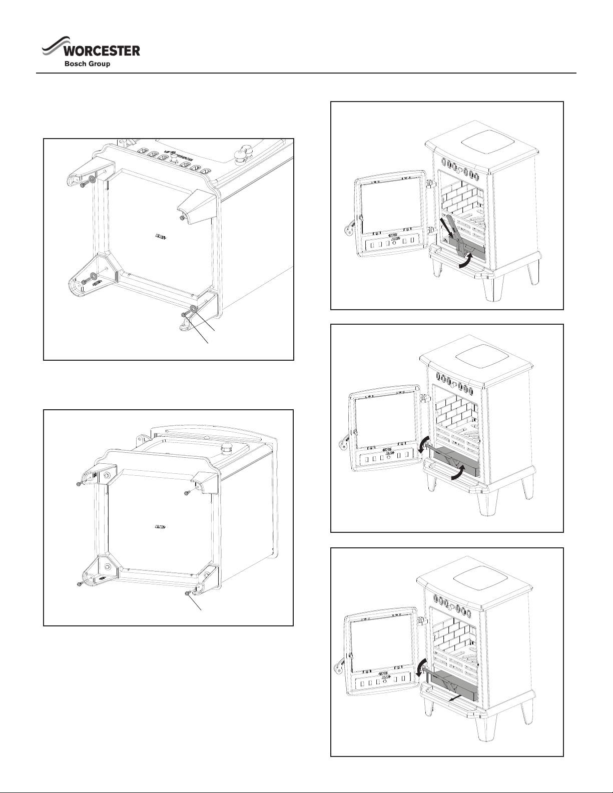
• Do not operate your appliance with the fueling door open. Only
operate with the fueling door open during ignition, refueling and
removal of residue material to prevent fume spillage. Operating
with the fueling door open can cause over-ring of your appliance.
Operation with the door open can cause excess smoke.
• This appliance is NOT suitable for installation in a shared ue
system.
• This appliance is suitable and has been tested for intermittent
operation.
• There must be no unauthorized modication of the appliance.
THE CLEAN AIR ACT 1993 AND SMOKE CONTROL
AREAS
Under the Clean Air Act local authorities may declare the whole
or part of the district of the authority to be a smoke control area. It
is an offence to emit smoke from a chimney of a building, from a
furnace or from any xed boiler if located in a designated smoke
control area. It is also an offence to acquire an “unauthorized fuel”
for use within a smoke control area unless it is used in an “exempt”
appliance (“exempted” from the controls which generally apply in
the smoke control area).
In England, appliances are exempted by publication on a list by the
Secretary of State in accordance with changes made to sections 20
and 21 of the Clean Air Act 1993 by section 15 of the Deregulation
Act 2015. Similarly in Scotland, appliances are exempted by
publication on a list by Scottish Ministers under section 50 of the
Regulatory Reform (Scotland) Act 2014.
In Wales and Northern Ireland, these are authorised by regulations
made by Welsh Ministers and by the Department of the Environment
respectively.
The Hanbury 4 has been recommended as suitable for use in smoke
control areas when burning wood logs or Defra exempt smokeless
fuel, when operated in accordance with these instructions and when
tted with a modication that prevents closure of the Secondary Air
control.
The Hanbury 5 has been recommended as suitable for use in smoke
control areas when burning wood logs or Defra exempt smokeless
fuel, when operated in accordance with these instructions and when
tted with a modication that prevents closure of the Secondary Air
control.
The Hanbury 8 has been recommended as suitable for use in smoke
control areas when burning wood logs or Defra exempt smokeless
fuel, when operated in accordance with these instructions and when
tted with a modication that prevents closure of the Secondary Air
control.
Further information on the requirements of the Clean Air Act can be
found here : https://www.gov.uk/smoke-control-area-rules
Your local authority is responsible for implementing the Clean Air Act
1993 including designation and supervision of smoke control areas
and you can contact them for details of Clean Air Act requirements.
PERMANENT AIR VENT
All stoves requires an adequate air supply in order to operate safely
and efciently. In accordance with current Building Regulations the
installer may have tted a permanent air supply vent into the room
in which the stove is installed to provide combustion air. This air
vent should not under any circumstances be shut off or sealed.
SETTING UP YOUR STOVE
Make sure that the room in which the stove is set up has at least
one door or window into the outside or is directly adjacent to such a
room. Other replaces or exhaust fans must not be operated in the
same room as this stove.
STOVES GUARANTEE - REGISTRATION
Please visit the website: worcester-bosch.co.uk/guarantee so that
you can register your stove online or via the Worcester Guarantee
App. Alternatively, if you wish to register your Worcester Greenstyle
Stove Guarantee via telephone please call 03301 232 552.
Required safety distances (minimum clearances to combustible
materials.
Hanbury 4 Hanbury 5 Hanbury 8
A > 1200mm
(toward the front of
the stove)
A > 1200mm
(toward the front of
the stove)
A > 1200mm
(toward the front of
the stove)
B > 600mm (to the
side)
B > 600mm (to the
side)
B > 700mm (to the
side)
C > 750mm (to the
back)
C > 725mm (to the
back)
C > 700mm (to the
back)

6 6720819898 C 11/2017
UNPACKING THE APPLIANCE
1. Remove the top section of the box.
2. Remove the remaining top panel.
3. Remove the bafe, fastener card, legs, ash pan, log guard,
glove, and ue collar from inside the rebox of the stove.
FASTENER CARD
INSTALLATION
Contents List
Qty. Item
1Bafe
1Fastener Card
4 Legs
1 Ash Pan
1Log Guard
1Glove
1Flue Collar
1 Ash PanTool

76720819898 C 11/2017
INSTALLATION
INSTALLING BAFFLE
REMOVING THE BAFFLE
► Lift the front edge of the bafe away from the support bars.
► Lift the bafe up off of the rear support bar.
► Lower the bafe and use the front door to remove it from the
unit.
► To replace the bafe simply reverse the order of the above
steps.
Note: Clean the bafe regularly to ensure safe and efcient
operation of the stove.
To locate the bottom of the bafe there is a H4, H5, or H8 (depending on the model purchased) cut into the bottom of the bafe
along with two arrows. When reinstalling the bafe be careful not to install the bafe upside down. When correctly installed the
H4, H5, or H8 cutout will rest on the rear liner as shown and the arrows will be pointing down.
1 2 3 4 5 6 7 8
9 10 11 12 13 14 15 16

8 6720819898 C 11/2017
INSTALLING THE LEGS
1. Align the leg with the stove.
2. Insert the provided (A) bolt and (C) washer.
3. Repeat for the remaining three legs.
LEG LEVELERS
Insert four (A) bolts into the bottom of the stove leg, and adjust as
needed for leveling.
REMOVING THE ASHPAN
INSTALLATION
A
C
A
A
C
A

96720819898 C 11/2017
INSTALLING THE BRICK LINERS
HANBURY 4
1. Install the rear liner rst.
2. Next install the grate. Note that there are two small notches
and two large notches. The two large notches must face to
the front of the stove or the grate will not correctly install.
3. Install the left and right brick liners (ip left brick liner to t).
4. Install the log retainer by sliding down into the slots located at
the front of the door.
INSTALLATION
Small Rear Notch
Large Front Notch
Small Rear Notch
Large Front Notch
Small Rear Notch
Large Front Notch
Small Rear Notch
Large Front Notch
Small Rear Notch
Large Front Notch

10 6720819898 C 11/2017
INSTALLING THE BRICK LINERS
HANBURY 5, 8
1. Insert the rear brick liner into the unit through the front door.
2. Next insert the right and left brick liners by sliding them down
into the slots provided.
3. Insert the grate.
4. Slide the log retainer down into the slots located at the front
of the door
INSTALLATION

116720819898 C 11/2017
INSTALLATION
CONVERTING TO USE REAR FLUE
1. Reach in through the front door of the stove and remove the
three (B) bolts, and (C) washers from the ue cover plate.
2. Reach in through the front door of the stove and remove the
three (B) bolts, and (C) washers, that are holding on the ue
collar.
3. Attach the ue collar to the rear of the unit with three (B) bolts
and (C) washers.
4. Attach the ue cover plate to the top of the stove with the three
bolts and washers you previously removed.
B
C
B
C
B
C
B
C

12 6720819898 C 11/2017
DIMENSION Hanbury 4 Hanbury 5 Hanbury 8
JStove Width 394mm 419mm 436mm
KStove Depth 325mm 341mm 440mm
LFront 225mm min. 225mm min. 225mm min.
MBack 150mm min. 150mm min. 150mm min.
NLeft 150mm min. 150mm min. 150mm min.
PRight 150mm min. 150mm min. 150mm min.
QTotal Width 694mm 719mm 736mm
RTotal Length 700mm 716mm 815mm
FREESTANDING
HEARTH
POSITIONING THE STOVE
It is very important to position the multifuel stove as close as
possible to the chimney, and in an area that will favour the most
efcient heat distribution possible throughout the house. The stove
must, therefore, be installed in the room where the most time is
spent and in the most spacious room possible. Recall that these
multifuel stoves produce radiating heat. A multifuel stove also
functions by convection, that is through the displacement of hot air
accelerated upwards and its replacement with cooler air.
The multifuel stove must not be connected to a hot air distribution
system since an excessive accumulation of heat may occur.
Your stove has been tested to applicable international standards
and therefore As a general rule, it is always advisable for a stove to
be installed upon a constructional hearth, but in certain instances
(when only being used to burn wood and not in a recess) it may be
installed upon a 12mm decorative, non-combustible hearth. If the
stove is installed in a recess, such as an inglenook replace, the
appliance must be installed on a constructional hearth.
NOTE: The appliance must be installed on oors with an adequate
load-bearing capacity. If an existing construction does not meet this
prerequisite, suitable measures (e.g. load distributing plate) shall
be taken to achieve it.
FLOOR LOADING CAPACITY
WARNING: Ensure that the load capacity of
the oor is sufcient to carry the weight of the
entire unit, before the stove is installed.
1 2 3 4 5 6 7 8
9 10 11 12 13 14 15 16
INSTALLATION
HANBURY 4 MODEL
WARNING: If multi-fuel is intended to be
burned in the Hanbury 4, this model must be
installed on a constructional hearth.
1 2 3 4 5 6 7 8
9 10 11 12 13 14 15 16

136720819898 C 11/2017
Diagram A Hearth suitable for a solid fuel appliance
Diagram B Hearth suitable for a solid fuel appliance
Section through hearth
Plan (a) Fireplace recess (b) Free standing
Top surface of hearth
At least
150mm
Projection
at least
500mm
from jamb
Air space of
at least 50mm
At least
250mm
Combustible material
At least 125mm
At least
840mm
At least
840mm
INSTALLATION
Hearths should be constructed of suitably robust materials and
to appropriate dimensions such that, in normal use, they prevent
combustion appliances setting re to the building fabric and
furnishings, and they limit the risk of people being accidentally
burnt.
The hearth should be able to accommodate the weight of the
appliance and its chimney if the chimney is not independently
supported.
Appliances should stand wholly above hearths made of non-
combustible board/sheet material or tiles at least 12mm thick, if
the appliance is not to stand in an appliance recess, or already on
a constructional hearth in accordance with the paragraph below.
CONSTRUCTIONAL HEARTH
Constructional hearths should have plan dimensions as shown in
Diagram A below and be made of solid, non-combustible material,
such as concrete or masonry, at least 125mm thick, including the
thickness of any non-combustible oor and/or decorative surface.
Combustible material should not be placed beneath constructional
hearths unless there is an air-space of at least 50mm between
the underside of the hearth and the combustible material, or the
combustible material is at least 250mm below the top of the hearth.
(See diagram B below)

14 6720819898 C 11/2017
FREE STANDING STOVE CLEARANCES
A multifuel stove must never be installed in a hallway or near a
staircase, since it may block the way in case of re or fail to respect
required clearances. It is of utmost importance that the clearances
to combustible materials be strictly adhered to during installation of
the stove. Refer to the tables below . Do not place any combustible
material within 1.2m of the front of the unit.
The clearance between the ue pipe and a wall are valid only for
vertical walls and for vertical ue pipe.
The chimney connector must not pass through an attic or roof
space, closet or similar concealed space, a oor, or a ceiling.
Transition must be made with a twin-wall chimney.
These stoves can be installed with a clearance of 50mm to non
combustible material If this reduced clearance installation is
performed, it is critical to respect the clearances to any combustible
materials in the proximity of this installation. Combustible materials
could include, but not be limited to, paint or a nish material on
the non-combustible materials. Combustible materials would
include these materials coming in contact with the non-combustible
materials.
DIMENSION Hanbury 4 Hanbury 5 Hanbury 8
ABackwall to Stove 750mm 725mm 700mm
BSidewall to Stove 600mm 600mm 700mm
CWall to corner (Angled Installation) 700mm 625mm 700mm
DBackwall to Flue 781mm 757mm 742mm
ESidewall to Flue 717mm 732mm 842mm
FWall to Flue (Angled Installation) 731mm 657mm 742mm
Combustible Side Wall
Combustible
Side Wall
Combustible Back Wall
Combustible
Back Wall
CORNER INSTALLATION
Combustible Side Wall
Combustible
Side Wall
Combustible Back Wall
Combustible
Back Wall
CORNER INSTALLATION
INSTALLATION

156720819898 C 11/2017
CHIMNEY CONNECTOR (STOVE PIPE)
The chimney connector should have a dimension of 125mm which
will t snuggly into the 127mm ue collar of your stove. If this is not
the case, we recommend you contact the dealer in order to ensure
there will be no problem with the draught.
The stove pipe must be made of aluminized or cold roll steel
with a minimum thickness of 0.53 mm. It is strictly forbidden to
use galvanized steel. Stove pipe made from vitreous enamel or
stainless steel is also acceptable.
The stove pipe should be assembled in such a way that the male
section (crimped end) of the pipe faces down. Attach each of the
sections to one another with three equidistant metal screws. Seal
with furnace cement.
The pipe must be short and straight. Any installation with a
horizontal run of chimney pipe must conform to Document J.
To ensure a good draught, the total length of the connecting ue
pipe should never exceed 2 m.
Installation of a draught damper is not recommended. Indeed, with
a controlled combustion multifuel stove, the draught is regulated
upon intake of the combustion air in the stove and not at the
exhaust.
REAR FLUE PIPE INSTALLATION
• Insert a tee into the ue collar. The tee piece is used as
cleaning access.
• Lift appliance into position. Take care not to damage the
hearth nish.
• Level the appliance
• Connect tee to the chimney using ue pipe
• Secure with self tapping screw
• Seal the connecting joints
Self tapping
screw at rear
Seal ue collar with
Fire Cement
Seal Collar with Fire Cement
Self tapping screw
Cap
600mm min
1000mm max
unsupported
Elbow with
access cover
To chimney connection
as detailed in building
regulations
600mm min
1000mm max
unsupported
Elbow with
access cover
To chimney connection
as detailed in building
regulations
Support as per chimney manufacture instructions.
INSTALLATION

16 6720819898 C 11/2017
Self tapping
screw at rear
Seal ue collar with
Fire Cement
Seal Collar with Fire Cement
Self tapping screw
Cap
600mm min
1000mm max
unsupported
Elbow with
access cover
To chimney connection
as detailed in building
regulations
600mm min
1000mm max
unsupported
Elbow with
access cover
To chimney connection
as detailed in building
regulations
Support as per chimney manufacture instructions.
TOP FLUE
REAR FLUE
INSTALLATION

176720819898 C 11/2017
CHIMNEY
In order for the stove to perform satisfactorily the chimney height
must be sufcient to ensure an adequate draught of approximately
15 Pa when hot so as to clear the products of combustion and
prevent smoke problems into the room.
NOTE: A chimney height of not less than 4.5 metres measured
vertically from the outlet of the stove to the top of the chimney
should be satisfactory. Alternatively the calculation procedure given
in EN 13384-1 may be used as the basis for deciding whether a
particular chimney design will provide sufcient draught. BS EN
15287-1:2007 gives additional details.
The outlet from the chimney should be above the roof of the building
in accordance with the provisions of Building Regulations Approved
Document J.
If installation is into an existing chimney then it must be sound and
have no cracks or other faults which might allow fumes into the
house. Older properties, especially, may have chimney faults or
the cross section may be too large i.e. more than 230 mm x 230
mm. Should remedial action be required, expert advice should be
sought. If it is found necessary to line the chimney then a ue liner
suitable for solid fuel must be used in accordance with Building
Regulations Approved Document J.
Any existing chimney must be clear of obstruction and have been
swept clean immediately before installation of the stove. If the stove
is tted in place of an open re then the chimney should be swept
one month after installation to clear any soot falls which may have
occurred due to the difference in combustion between the stove
and the open re.
If there is no existing chimney then any new system must be to
the designation described above and in accordance with Building
Regulations Approved Document J.
A single wall metal uepipe is suitable for connecting the stove to
the chimney but is not suitable for use as the complete chimney.
The chimney and connecting uepipe must have a minimum
diameter of 125mm and its dimension should be not less than the
size of the outlet socket of the stove.
Any bend in the chimney or connecting uepipe should not exceed
45°, 90° bends should not be used.
Combustible material should not be located where the heat
dissipating through the walls of replaces or ues could ignite it.
Therefore when installing the stove in the presence of combustible
materials due account must be taken of the guidance on the
separation of combustible material given in Building Regulations
Approved Document J and also in these stove instructions.
If it is found that there is excessive draught in the chimney then a
draught stabiliser should be tted. Fitting of a draught stabilizer will
affect the requirement for the permanent air supply into the room in
which the stove is tted in accordance with Approved Document J
(see also combustion air supply).
Adequate provision e.g. easily accessible soot door or doors must
be provided for sweeping the chimney and connecting uepipe
where it is not intended for the chimney to be swept through the
appliance.
This stove may be connected with a factory built or masonry
chimney with a minimum diameter of 125mm. If you are using
a factory built chimney, it must comply with BS EN 1856-1:2003
standard. It is very important that it is installed according to the
manufacturer’s specications.
If you are using a masonry chimney, it is important that it be built in
compliance with the specications contained in Document J.
The interior diameter of the chimney ue must be no smaller than
the diameter of the stove smoke exhaust pipe. A ue which is too
small may cause draught problems, while a large ue promotes
rapid cooling of the gas, and hence the build-up of creosote and the
risk of chimney res. Note that it is the chimney and not the stove
which creates the draught effect; the stove’s performance is directly
dependent on an adequate draught from the chimney.
Installation of an interior chimney is always preferable to an exterior
chimney. Indeed, the interior chimney will, by denition, be hotter
than an exterior chimney, being heated up by the ambient air in the
house. Therefore the gas which circulates will cool more slowly,
thus reducing the build-up of creosote and the risk of chimney
res. The draught caused by the tendency for hot air to rise will be
increased with an interior chimney.
Using a chimney cap at the extremity of the chimney requires
regular inspection in order to ensure that it is not obstructed thus
blocking the draught, and it should be cleaned when used regularly.
Exterior chimney should be double or triple wall.
CONNECTION TO CHIMNEY
Stoves may have a choice of either a rear or top ue gas
connector that allows connection to either a masonry chimney or a
prefabricated factory-made insulated metal chimney in accordance
with their instructions.
REGULAR CLEANING
It is important that the appliance, ue gas connector and chimney
are regularly cleaned and checked for any possible blockages prior
to re-lighting after a prolonged shut down.
INSTALLATION

18 6720819898 C 11/2017
FLUE OUTLET POSITIONS FOR SOLID FUEL APPLIANCES
150mm
max. Datum for vertical
measurements
The datum for vertical measurements is the
point of discharge of the flue, or 150mm
above the insulation, whichever is the lower
Datum for
horizontal
measurements
Adjacent building
Regulated building
A
B
C
D
weather surface (Notes 1,2)
A At or within 600mm of the ridge At least 600mm above the ridge
BElsewhere on a roof (whether
At least 2300mm horizontally
from the nearest point on the
weather surface and:
a) at least 1000mm above the
highest point of intersection of
the chimney and the weather
surface; or
b) at least as high as the ridge.
C
Below (on a pitched roof) or
within 2300mm horizontally to an
or other opening (Note 3)
At least 1000mm above the top
of the opening.
D
Within 2300mm of an adjoining
or adjacent building, whether or
not beyond the boundary (Note 3)
At least 600mm above any part
of the adjacent building within
2300mm.
Notes
1) The weather surface is the building external surface, such as its roof,
tiles or external walls.
3) The clearances given for A or B, as appropriate, will also apply.
INSTALLATION

196720819898 C 11/2017
INSTALLATION
FACTORY BUILT CHIMNEY
When a metal prefabricated chimney is used, the manufacturer’s
installation instructions must be followed. You must also purchase
(from the same manufacturer) and install the ceiling support
package or wall pass-through and “T” section package, restops
(where needed), insulation shield, roof ashing, chimney cap, etc.
Maintain proper clearance to the structure as recommended by the
manufacturer. The chimney must be the required height above the
roof or other obstructions for safety and proper draught operation.
Ways of meeting the requirements when proposing factory-made
metal chimneys include:
• Using component systems appropriately designated in
accordance with BS EN 1856-1:2003 to suit the appliance
and installing them in accordance with the relevant
recommendations of BS EN 15287-1:2007
Where a factory-made metal chimney passes through a wall,
sleeves should be provided to prevent damage to the ue or
building through thermal expansion. To facilitate the checking of
gas tightness, joints between chimney sections should not be
concealed within ceiling joist spaces or within the thickness of walls.
When providing a factory-made metal chimney, provision should
be made to withdraw the appliance without the need to dismantle
the chimney.
Factory-made metal chimneys should be kept a suitable distance
away from combustible materials. Ways of meeting the requirements
for chimneys designated to BS EN 1856-1:2003 comprise:
• Locating the chimney not less than distance ‘xx’ from
combustible material, where ‘xx’ is dened in BS EN 1856-
1:2003 as shown in the diagram below.
• Where a chimney passes through a cupboard, storage space
or roof space, providing a guard placed no closer to the outer
wall of the chimney than the distance noted above.
Non-combustible
plate with spacer,
e.g. manufacturer’s
fire stop component
No combustible material in
shaded zone. Width of
shaded zone at least equal to
manufacturer’s declared
minimum distance (xxmm) as
designated to BS EN 1856-1
Distance xx
Plasterboard
Timber
The separation of combustible material from a factory-made metal chimney designated to BS EN 1856-1:2003
USE OF FLEXIBLE METAL FLUE LINERS FOR THE RELINING OF CHIMNEY
A way of relining an existing chimney would be to use a exible
metal ue liner, appropriately designated in accordance with BS EN
1856-2:2004 to suit the appliance, fuel and ue gas characteristics.
Flexible ue liners should only be used to reline an existing chimney
and should not be used as the primary liner of a new chimney.
1 2 3 4 5 6 7 8
9 10 11 12 13 14 15 16
Always follow the manufacturer’s instructions when installing the factory built chimney system and related components. Document
J can also be a good reference for installation. All local codes must be followed during installation.

20 6720819898 C 11/2017
INSTALLATION
LOCATION AND SHIELDING OF CONNECTING FLUEPIPES
Connecting uepipes should be used only to connect appliances
to their chimneys. They must not pass through any roof space,
partition, internal wall or oor, except to pass directly into a
chimney through either a wall of the chimney or a oor supporting
the chimney. Connecting uepipes should also be guarded if they
could be at risk of damage or if the burn hazard they present to
people is not immediately apparent.
Connecting uepipes should be located so as to avoid igniting
combustible material. Ways of meeting the requirement include
minimizing horizontal and sloping runs and:
• Following the guidance as noted above where the connecting
uepipe is a factory-made metal chimney is at least equal
to designation BS EN 1856-1:2003 and installed to BS EN
15827-1; or
• Separation by shielding in accordance with the diagram below:
Elevation
without shield
Elevation
with shield
Plan without
shield
Shields should either:
a) extend beyond the fluepipe by at least 1.5 x D; or
b) make any path betweeb fluepipes and combustible
material at least 3 x D long.
Air space of at least 12mm
between non-combustible
shield and combustible
material
Plan with
shield
Indicates combustible
material
Protecting combustible material from uninsulated uepipes for solid fuel appliances
AIR REQUIREMENTS AND ASSESSING AIR PERMEABILITY OF OLDER DWELLINGS IN RELATION TO
PERMANENT VENTILATION REQUIREMENTS
It is important to note for proper operation, this appliance requires
room air to function efciency. Therefore, a calculation of the air
requirements should be performed before and after installation for
proper and efcient operation of this product.
As a guide, this appliance requires 3410mm² of permanently open
vent in a well-sealed house, but this reduces to 660mm² for a
house with much higher air permeability. It is unlikely that a house
built before 2008 will be well-sealed unless extensive measures
have been taken to improve air tightness.
Older houses are unlikely to have been tested but are unlikely to
achieve an air permeability of less than 5.0 m3/(h.m2) at 50Pa
unless the building fabric has been substantially upgraded.
This manual suits for next models
5
Table of contents
Other Bosch Stove manuals
Popular Stove manuals by other brands

Chesney's
Chesney's 8 Series User and installation instructions

Dean Forge
Dean Forge Dartmoor Baker 5E Eco operating instructions

Total
Total 03/T600AF Instructions for use

Italiana Camini
Italiana Camini NELLY PIU Installation, use and maintenance

Pelpro
Pelpro PPC90 Service manual

Quadra-Fire
Quadra-Fire 18000 FreeStanding Installation & operation manual

WANDERS
WANDERS Cocos User guide and installation manual

Stuv
Stuv 30 Compact User instructions

Hi-Flame
Hi-Flame HF-517U Installation and operation instruction

Brunner
Brunner 0708043N Instructions for use

Electralog
Electralog CS4416 Practical user's guide

Jøtul
Jøtul GF 370 DV Installation and operation instructions