Boss Industrial ED16T21 User manual

DUAL ACTION
ELECTRIC LOG SPLITTER
16 TON
MODEL NO.: ED16T21
Owner’s Manual
ASSEMBLY & OPERATING INSTRUCTIONS
Purchase Date___________________ Serial No.______________________
Dealer________________________________________________________
Boss Industrial, Inc. • 1208 N. Independence Blvd • Romeoville, IL 60446 • USA
Phone: (800) 780-BOSS (2677) • Fax (331) 472-2976
www.boss-industrial.com
2020-01 GB

To The Owner
Thank You!
Thank you for purchasing a BOSS Log Splitter. It was carefully engineered to provide excellent performance when properly
operated and maintained.
Please read this entire manual prior to operating the equipment. It instructs you how to safely and easily set up, operate
and maintain your machine. Please be sure that you, and any other persons who will operate the machine, carefully
follow the recommended safety practices at all times. Failure to do so could result in personal injury or property damage.
All information in this manual is relative to the most recent product information available at the time of printing. Review
this manual frequently to familiarize yourself with the machine, its features and operation. We reserve the right to change
product specifications, designs and equipment without notice and without incurring obligation.
This unit is designed to use on a power supply that is 115 volts, 60 Hz, AC only (household current of 20 amp specially). If
you have any problems or questions concerning the machine, phone an authorized service dealer or contact us directly.
Boss Industrial’s customer support phone number, website and mailing address can be found on this page. We want to
ensure your complete satisfaction at all times.
Throughout this manual, all references to right and left side of the machine are observed from the operating position.
Boss Industrial, Inc. is responsible for all equipment-related issues with regards to performance, power-rating,
specifications, warranty and service. Please refer to the Warranty terms included in this Owner’s/Operator’s Manual for
more information.
Read and thoroughly understand all instructions and safety information before assembling or operating this log
splitter. Failure to do so may cause serious injury or death. Do not allow familiarity with tools to make you
careless. Remember that a careless fraction of a second is sufficient to inflict serious injury.
Customer Support
Please do NOT return the machine to the retailer or dealer without first contacting the Customer Support
Department.
If you have difficulty assembling this product or have any questions regarding the controls, operation, or maintenance of
this machine, you can seek help from the experts. Choose from the options below:
◊Visit us on the web at www.boss-industrial.com
◊Call a Customer Support Representative at (800) 780-2677 or send an email to: service@boss-industrial.com
◊Write to Boss Industrial, Inc., 1208 N. Independence Blvd, Romeoville, IL 60446

Table of Contents
Page(s)
Section I: Know Your Log Splitter...........................................................................................................................1-6
Log Splitter Overview.....................................................................................................................................1
Safety Decals..............................................................................................................................................2-3
Important Tips................................................................................................................................................4
Operator Zone................................................................................................................................................4
Electrical Safety.............................................................................................................................................5
Hydraulic Safety ............................................................................................................................................6
Section II: Pre-Operation Instructions...................................................................................................................7-12
Unpacking ..................................................................................................................................................7-8
Assembling...............................................................................................................................................8-12
Getting Prepared..........................................................................................................................................13
Section III: Operation Instructions.......................................................................................................................14-15
Section IV: Maintenance.....................................................................................................................................16-18
Off Season Storage......................................................................................................................................16
Transportation.........................................................................................................................................16-17
Maintenance & Adjustment.....................................................................................................................17-18
Trouble Shooting..........................................................................................................................................19
Technical Specifications..........................................................................................................................................11
Exploded Diagram & Parts List...........................................................................................................................20-22
Warranty..................................................................................................................................................................23
Packing List..............................................................................................................................................................24

DANGER! This machine was built to be operated according to the safe operation practices in this
manual. As with any type of power equipment, carelessness or error on the part of the operator can
result in serious injury. This machine is capable of amputating hands and feet and throwing debris.
Failure to observe the following safety instructions could result in serious injury or death.
The following signal words and meanings are intended to explain the levels of risk associated with this product.
DANGER indicates a hazardous situation which, if not followed, will
result in serious injury or death.
WARNING indicates a hazardous situation which, if not avoided, could
result in serious injury or death.
CAUTION indicates a hazardous situation which, if not avoided,
could result in minor or moderate injury.
NOTICE is important information about the proper use of your
machine. Failure to follow this instruction could result in damage to
your machine.
1
(FIGURE 1)
Part I: Know Your Log Splitter
SECTION I: KNOW YOUR LOG SPLITTER
LOG SPLITTER OVERVIEW
Safety Chain
Tongue
End Plate
End Plate
Log Tray
Double Direction
Splitting Wedge
Control Handle
Valve Cover
Electric Motor
Power Cable
Electric Box
Oil Suction
Hose
D.O.T. Tire
Jack Stand
Beam
Dipstick
Reservoir

Make sure that all safety warning decals are in good condition and readable. Always replace missing or defaced decals.
Contact Boss Industrial, Inc. at 1-800-780-2677 for replacement decals.
1. Safety Warning / Operating Label (Part #: 410-174)
3. Pinch Point Warning Label (Part #: 410-233, 410-235)
4. Motor Label (Part #: 410-305) 5. Switch Label (Part #: 410-159)
6. Serial NO. / Spec. Label (Part #: 410-517)7. Oil Label (Part #: 410-647)
2
SAFETY DECALS
2. Towing Safety Label
(Part #: 410-429)

Study the following symbols used on this tool and learn their meaning. Proper interpretation of these symbols will
allow you to operate the tool better and safer.
Wet Conditions Alert Do not expose to rain or use in damp locations.
Read The Operator’s Manual
To reduce the risk of injury, user must read and understand
operator’s manual before using this product.
Eye, Face & Ear Protection Always wear safety goggles or safety glasses with side
shields, earplugs and a face shield when operating this
product.
Safety Alert Precautions that involve your safety.
Wear Gloves Always wear nonslip, heavy-duty protective gloves when
operating this product.
Wear Safety Footwear Always wear nonslip safety footwear when operating this
product.
Keep Bystanders Away Always keep bystanders at least 25 ft. (7.5 m) away.
Single Operator Only one person should operate the machine at a time. The
adult who loads and stabilizes the log must be the person
who operates control handle.
WARNING— Pressurized
Fluid
Never check for hose leaks with your hands. High pressure
fluid can escape through a pin hole leak and cause serious
injury by puncturing the skin and causing blood poisoning.
Keep Hands Away Always keep hands away from the wedge and the ram.
Pinch Point Never touch the cylinder bed, ram, or wedge during machine
operation.
Rotating & Moving Parts
Alert Beware of rotating and moving parts, serious injury could
occur.
Electric Shock Alert Never touch damaged or exposed wires while the machine is
connected to a power source.
3

1. DO NOT discard packing materials until you have carefully inspected and satisfactorily operated the tool.
2. Read, understand, and follow all instructions on the machine and in this manual and the engine manual before
attempting to assemble and operate. Keep the manuals in a safe place for future and regular reference and for ordering
replacement parts.
3. Lubricate the wedge and upper side of the machine body for splitting smoothly. See FIGURE 1
4. Check the oil level before every operation.
5. Sharpen the wedge periodically.
6. USE only an electrical circuit having adequate capacity as recommended.
7. DO NOT continue to push on the control handle more than 3 seconds if the wedge can’t cut through an oversized
or extremely hard log. Force the tool will cause permanent damage and void warranty.
8. Try to split from another end or cut a small piece from the border instead of the center when you fail to cut
through an oversized log.
9. Release the handle lever right before the cylinder is extended or retracted fully. Keep holding the control lever as
the wedge reaches to the farthest positions will cause the valve squeezed. When this happens, you must turn off
the motor to relieve pressure and restart the tool to operate.
10. Move the control handle to Forward or Backward position gently to operate. Push or pull hard on the control handle
lever won’t help generate more power, but break the handle or damage the internal valve parts and void warranty.
11. DO NOT expose this machine to rain or use in a damp environment.
ONLY operate the log splitter from the operator zone as shown below. The operator has the safest and most efficient
access to the control valve and the beam in this location. Failure to operate the log splitter in this position can result in
serious injury or death. See FIGURE 2
4
IMPORTANT TIPS
OPERATOR ZONE
(FIGURE 2)
Operator Zone
Operator Zone

1. This tool is powered by a precision built electric motor. Use only an electrical circuit having adequate capacity as
recommended by the manufacturer -- 115 volts, 60 Hz, 20 Ampere household current, AC only. Do not operate this tool
on direct current (DC). If you choose to connect the tool to a generator, make sure the generator carrying the current
(Amperes) or power output (Watts) at least 50% more than motor rated power.
2. A substantial voltage drop will cause a loss of power and the motor will overheat. If the machine does not operate when
plugged into an outlet, double check the power supply.
3. For voltage, the wiring is as important as the motor’s horsepower rating. A line intended only for lights cannot properly
carry a power tool motor. Check the house wiring if you experience circuit breaker tripped or fuse blown even the
motor is plugged into a wall outlet directly.
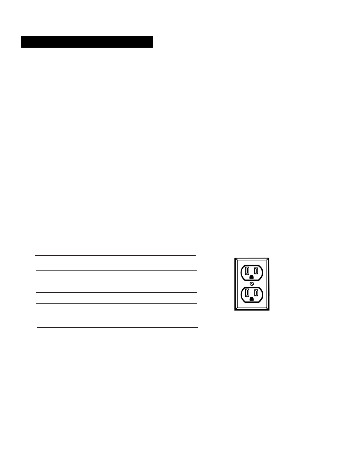
4. This tool is intended for use on a circuit that has an outlet like the one shown below (FIGURE 3). Ensure that the outlet
has a grounding pin that is properly installed and grounded in accordance with all local codes and ordinances to reduce
the risk of electric shock. Check with a qualified electrician or service personnel if the grounding instructions are not
completely understood, or if in doubt as to whether the tool is properly grounded.
5. Check that the switch, cable and plug are not damaged before each use to avoid electric shock or short circuit.
6. Use only 3-wire extension cords with 3-prong grounding plugs, and 3-pole receptacles that accept the tool's plug.
7. When using a power tool at a considerable distance from the power source, use an extension cord heavy enough to carry
the current that the tool will draw. An undersized extension cord will cause a drop in line voltage, resulting in a loss of
power and causing the motor to overheat.
8. Use the chart provided below to determine the minimum wire size required in an extension cord. Only round jacketed
cords listed by Underwriter's Laboratories (UL) should be used.
**Ampere rating (on tool faceplate)
0-2.0 2.1-3.4 3.5-5.0 5.1-7.0 1-12.0 12.1-16.0
Cord
Length
Wire Size
(A.W.G.)
25' 12 12 12 10 10 10
50' 12 12 10 10 ——
100'
10
10
10
—
—
—
**Used on 12 gauge - 20 amp circuit only.
NOTE: AWG = American Wire Gauge
9. When working with the tool outdoors, use an extension cord that is designed for outside use. This is indicated by the
letters "WA" on the cord's jacket.
10. Keep the extension cord clear of the working area. Position the cord so that it will not get caught on lumber, tools or
other obstructions while you are working with a power tool. Failure to do so can result in serious injury.
11. “BLOWING” a fuse or tripping a circuit breaker is usually a warning that you are overloading the machine or have too
many devices taking power from the circuit, or both. DO NOT install a higher capacity fuse!
12. DO NOT leave the motor running unattended.
13. DO NOT expose the motor to rain or use / store in damp locations.
5
ELECTRICAL SAFETY
(FIGURE 3)

1. The hydraulic system of your log splitter requires careful inspection along with the mechanical parts. Be sure to replace
frayed, kinked, cracked or otherwise damaged hydraulic hoses or hydraulic components.
2. NEVER check for leaks of hydraulic fluid with your hand. Fluid escaping from a small hole can be almost invisible.
Escaping fluid under pressure can have sufficient force to penetrate skin causing serious personal injury or even death.
Leaks can be detected by passing a piece of cardboard over the suspected leak and looking for discoloration.
3. ALWAYS seek professional medical attention immediately if injured by escaping hydraulic fluid. Serious infection or
reaction can develop if proper medical treatment is not administered immediately.
4. ALWAYS be sure to relieve all pressure by shutting off the motor and moving the control handle back to stop position.
5. NEVER remove the vent plug from the hydraulic tank or reservoir while the log splitter is running. The tank could contain
hot oil under pressure which could result in serious injury.
6. NEVER adjust the hydraulic valve. The pressure relief valve on your log splitter is preset at the factory. Only a qualified
service technician should perform this adjustment.
7. NEVER operate your log splitter near a flame or spark. Hydraulic oil is flammable and can explode.
8. ALWAYS take a Class B fire extinguisher with you when operating this log splitter in dry areas as a precautionary
measure against possible flying sparks.
CALIFORNIA PROPOSITION 65
WARNING! Engine Exhaust, some of its constituents, and certain components contain
or emit chemicals known to State of California to cause cancer and birth defects or
other reproductive harm. For more information, please go to www.P65Warnings.ca.gov.
6
HYDRAULIC SAFETY

WARNING! This product has been shipped partially assembled. Use extreme caution unpacking this machine.
Some components are very heavy and will require additional people or mechanical lifting tools.
Unpacking tools needed:
1. Wrench 13mm
2. Scissors or knife
3. Pry bar or claw hammer
Step 1: Use a 13mm wrench to remove the bottom bolts securing the crate side frames onto the crate bottom, lift the
crate top and the cardboard box up and put them aside together. See FIGURE 4.
Step 2: Carefully remove all loose parts included in the container, e.g. Electric motor / pump box, etc.
Step 3: Use scissors or a knife to cut and remove the straps securing the parts to the beam or tank assembly, including
wheels, tongue assembly and log tray assemblies, then put aside these parts for installation.
NOTE: DO NOT remove the strap securing the hydraulic hoses to the beam at this time, until you do the procedure to
connect the hoses.
Step 4: Open the Motor / pump assembly box, and then put aside the parts and instruction manual carefully for
installation.
7
SECTION II: PRE-OPERATION INSTRUCTIONS
UNPACKING
(FIGURE 4)
Crate Top
Cardboard box
Crate Bottom

Step 5: Use a pry bar or claw hammer to remove the plywood splinters securing the beam and tank assemblies on the
crate bottom. Take out the two heavy assemblies.
NOTE: Due to the weight / size of the two assemblies, it’s recommended two or more adults to assist lifting and moving
the two assemblies. Lifting tools such as hoist, crane, jack, etc. are also recommended.
Step 6: Inspect if all component assemblies, parts and accessories are included as listed in the Packing List (Page 24). If
any parts are damaged or missing, please call our customer service department at 1-800-780-2677 or send an email to
service@boss-industrial.com for assistance.
Assembling tools needed:
1. Wrench 13mm x 2 5. Needle nose pliers x 1
2. Wrench 18, 19, 27mm one each 6. Flat head screwdriver x 1
3. Adjustable wrench x 1 7. Soft faced hammer x 1
4. Thread locking compound x 1
STEP 1: Install the tongue and jack stand assembly. See FIGURE 5.
1. Raise the beam assembly cross onto one end of the crate cover. Two or more people are recommended to
assist with raising the beam and securing it while the other(s) install the jack stand and reservoir tank.
2. Remove the spring clip (Ø3) and clevis pin (Ø10 x 85) which hold jack stand on the tongue, and then pivot the jack
stand towards the ground. Secure the jack stand in position with the clevis pin and spring clip just removed.
3. Remove the 6 sets of M12 hardware on both sides of the front end of the beam.
4. Position the mounting brackets of the tongue assembly inside the bottom of the main beam and align the holes.
Screw on the Bolts M12 x 35 just removed and tighten using a 18mm wrench for the bolts and a 19mm
wrench for the lock nuts.
8
ASSEMBLING
(FIGURE 5)

STEP 2: Install the reservoir tank. See FIGURE 6
1. Remove the 4 sets of M12 hardware on both sides of the rear end of the beam.
2. Position the beam support brackets on the tank assembly inside the bottom of the main beam and align the holes.
Screw on the Bolts M12 x 35 just removed and tighten using a 18mm wrench for bolts and a 19mm wrench for
the lock nuts. You may need another helper to lift up the tank to align the holes.
STEP 3: Install the two wheels. See FIGURE 7.
1. Remove the plastic shipping caps from the wheels and slide the wheels onto the wheel axels.
2. Screw the castle nuts onto the axels and tighten with an adjustable wrench to seat the bearings. Then back the
castle nuts off one half turn and snug them up to the bearings, so they line up with the hole in the axel.
3. Insert the split pin into the slot of castle nut and the hole in the axel, and then bend the ends of the pin with needle
nose pliers keeping it close to the castle nut so the dust cap fits over it.
4. Tap the dust caps onto the wheel using a soft faced hammer.
5. Raise the towing hitch up and stand the machine down to the ground.
9
(FIGURE 7)
(FIGURE 6)

REF. NO. DECSRIPTION QTY.
1
D.O.T. Tire / Wheel
2
2
Hardware Kit #2, including:
1
2-1
Castle nut / 1-14
2
2-2
Split pin / Ø4 x 50
2
2-3
Dust cap
2
STEP 4: Install the motor / pump assembly. See FIGURE 8.
1. Align the four mounting hole positions on the motor and the mount plate.
2. Secure the motor with the M8 hardware, then tighten the harware using two 13mm wrenches.
REF. NO. DECSRIPTION QTY.
3
Engine / Pump assembly
1
4
Hardware kit # 5-3, including:
1
4-1
Hex head bolt / M8 x 40
4
4-2
Flat washer / M8
8
4-3
Lock nut / M8
4
STEP 5: Attach the hoses. See FIGURE 9.
The three hydraulic hoses listed below, each of them has one end fixed on the log splitter by Manufacturer, the other
end left open to be attached.
1. Oil suction hose Ø19, labeled as ①, comes from the bottom of the reservoir.
Loosen the hose clamp on the open end of this hose using a flat head screwdriver, and connect the hose to the
fitting on the bottom of the pump, which is also labeled as ①. Tighten the hose clamp.
2. Pump / Valve connecting hose ½”, labeled as ②, comes from the left side of the valve on the beam assembly.
Screw the open end of this hose onto the fitting on top of the pump, which is also labeled as ②.Tighten using a
27mm wrench or an adjustable wrench.
3. The oil return hose 1/2” labeled as ③ comes from the right side of the valve on the beam assembly, screw the
open end of this hose onto the fitting on the reservoir, which is also labeled as ③for easy installation. Tighten the
hose fiting using a 27mm wrench or an adjustable wrench.
10
(FIGURE 8)

STEP 6: Install the log tray assemblies and control handle lever. See FIGURE 10.
1. Remove the M8 hardware fixed on the tabs on both sides of the beam. Align the holes on the log tray frames and
the tabs, and secure with the M8 hardware just removed using a 13 mm wrench.
2. Screw the control handle lever into its linkage part on top of the valve.
11
(FIGURE 9)
(FIGURE 10)
Left side
Right side

STEP 7: Fill hydraulic oil. See FIGURE 11.
The log splitter is shipped without hydraulic fluid in the reservoir. You must fill the reservoir before your initial use. The
oil dipstick is packed in the Motor-Pump assembly box.
1. Please select the oil based on the outside temperature range the log splitter will be used in. Refer to the chart
provided to select the appropriate hydraulic oil. The machine was tested by the manufacturer using AW32 oil, so
that AW32 oil is highly recommended for most users in most areas.
The reservoir tank has a capacity of 3.5 gallons of hydraulic fluid. You may need prepare more oil than the tank
capacity because a lot of oil will be drawn into hydraulic cylinder, valve, pump and hoses.
0°10° 20° 30° 40°50°60°70°80°90°
(-18°) (-12°) (-7°) (-1°) (4°) (10°) (16°) (21°) (27°) (32°)
2. Slowly fill the reservoir until the oil level reaches the maximum line on the dipstick.
3. When checking the fluid, always make sure to push the dipstick all the way down to make sure you are getting
an accurate reading.
4. Start the motor and use the control handle to engage the wedge to the farthest extended position and then retract
fully. Repeat this operation for 12 cycles to repel the air trapped in the hydraulic system. Much of the fluid will be
drawn into the cylinder and hoses. Stop the motor, and check the oil level as instructed below.
NOTE: Make sure the oil level is above the bottom line on the dipstick. If not, refill the reservoir to prevent damage
to the hydraulic pump. DO NOT overfill. Some fluid may overflow from the ventilator as the system builds heat and
the fluid expands and seeks a balanced level. Place a container underneath the tank to collect the spilled oil.
4. However, you MUST check the fluid level before each operating. If not filled, proceed with above steps.
12
(FIGURE11)
ISO 68
ISO 46
ISO 32
ISO 22
Approved fluids include Shell Tellus® S2 M 32
Hydraulic Fluid, Dexron® III / Mercon® automatic
transmission fluid, Pro-Select™ AW-32 Hydraulic Oil
or 10WAW-ISO viscosity grade 32 hydraulic oil. It is
not recommended that fluids be mixed, to top off the
reservoir tank during initial set-up use Shell Tellus®
S2 M 32 Hydraulic Fluid only.

●Place the log splitter on flat, dry, solid ground in an open area.
●Lubricate the beam area (where the splitting wedge will slide) with engine oil. Do not use grease. See FIGURE 1.
●Block both wheels to prevent your log splitter from moving during operation.
●Check all nuts, bolts and hydraulic fittings are tight to be sure the equipment is in a safe working condition.
●Wear safety gear such as goggles or safety glasses, steel toed shoes and tight fitting gloves (without loose cuffs or draw
strings), a protective hearing device and suitable work clothing. NEVER wear loose clothing or jewelry that can be
caught by moving parts of the log splitter.
●Both ends of the log should be cut as square as possible to help prevent the log from riding out during operation.
●ALWAYS check the hydraulic oil level before you start the log splitter.
●ALWAYS check the machine with no frayed, kinked, cracked, or damaged hoses, fittings, or tubing before operation.
NOTES:
1. ALWAYS read the operator’s manual before operation.
2. NEVER allow children under 16 years of age to operate this log splitter. NEVER allow adults lacking proper instructions
and understanding to operate this log splitter.
3. NEVER operate the log splitter when tired or under the influence of alcohol, drugs or medication.
4. ALWAYS use eye protection which is marked to comply with ANSI Z87.1.
5. NEVER use this log splitter for any purpose other than splitting wood. It is designed for this use only. Any other use can
cause serious injury or death.
6. Check that the switch, power cable and plug are not damaged (no cracks, etc.) to prevent the risk of electric shock or a
short circuit.
7. Check that all nuts, bolts and hydraulic fittings are tight to be sure the equipment is in a safe working condition.
8. Ensure that the horizontal distance between the splitter and outlet is more than 5 feet.
9. Be familiar with all controls and proper operation. Know how to stop the machine quickly in the event of any malfunction
or emergency.
13
GETTING PREPARED

8
•Plug the machine into a 3 pole outlet and start the motor (20 AMP circuit required.)
•Grab the log on the sides and place it firmly on top of the beam against the end plate. See FIGURE 13
•Use your right hand to push the control handle lever to the Forward or Reverse position to split the wood. See
FIGURE 13.
The control handle has three positions. See FIGURE 12.
•Stabilize the log using your left hand when needed. Remove your hand immediately as the wedge starts
to contact the log.
•Release the control handle to stop the wedge movement at any point in the splitting process if you feel an unsafe
splitting condition is occurring. The control handle will return to the Neutral position automatically when you release it.
14
SECTION III: OPERATION INSTRUCTIONS
(FIGURE12)
Neutral
Reverse
Forward
FORWARD — Move the control handle to the FORWARD
position which will engage the wedge forward to split the log.
NEUTRAL — Release the control handle to the NEUTRAL
position, the wedge stops moving at any point during splitting.
REVERSE — Move the control handle to the REVERSE
position which will pull the wedge backward to split another log.
NOTE: DO NOT continue holding the handle when the wedge
is fully extended or retracted to the farthest positions, which
may cause the valve squeezed. When this happens, you
must turn off the motor to relieve the pressure and restart
the tool to operate.
(FIGURE13)
Right Hand
Left Hand

•Remove partially split wood from wedge.
1) If the log is clipped or jammed on the wedge, release the control handle and shut off the engine immediately.
Gently knock off the log with a hammer or mallet (not with your hands).
WARNING! Never remove partially split wood from the wedge with your hands. Fingers may become
trapped between the split wood.
2) Once removed from the wedge, split the wood from the opposite end or in another location.
•Shut off the motor after splitting and relieve hydraulic system pressure by cycling the valve control lever from forward to
reverse several times. Leave the handle to neutral before storage or maintenance.
NOTES
1. NEVER place hands or feet between the extending wedge and the end plates. Failure to do so may result in crushed or
amputated fingers, toes, hand, or foot.
2. NEVER straddle or step over the log splitter during operation.
3. NEVER reach crossly and attempt to catch a falling split wood — let it fall.
4. NEVER try to split two logs on top of each other.
5. NEVER try to cross split a log.
6. NEVER attempt to load your log splitter when the wedge is in motion.
7. ALWAYS use your hand to operate the control lever on the valve. NEVER use your foot, a rope or any extension device.
8. ONLY operate your log splitter in daylight or under good artificial light.
9. ALWAYS keep the work area clean. Remove split wood around your log splitter immediately so that you don’t stumble
over it.
10. DO NOT allow familiarity with tools to make you careless. Remember that a careless fraction of a second is sufficient to
inflict serious injury.
11. ALWAYS clear the wood chips inside the machine body where the cylinder travels in case damages to the valve.
12. ONLY a single operator is allowed to load and operate this log splitter. Keep bystanders, helpers, pets and children
a sufficient distance at least 25 feet from the machine.
13. DO NOT force the tool. It is designed to operate within its maximum speed and tonnage. No continuing to push on the
control handle for more than 3 seconds. If you experience extremely hard wood, release the control handle at once
to avoid permanent damage which will void warranty. If the motor stops, turn off the motor and then turn it back on
again to continue splitting.
14. NEVER leave this machine unattended with the engine running.
15. NEVER operate your log splitter when it is in poor mechanical condition or in need of repair.
16. DO NOT pull on the power supply cable to unplug the machine.
15

If the log splitter will not be used for more than 30 days, prepare it for storage as follows:
•Store unit in a clean, dry area inside. Make sure it’s switched off and unplugged.
•Allow the machine to cool 5 minutes after use before storing.
•Protect power supply cable from heat, sunshine, aggressive liquids and sharp edges.
•Clean the log splitter thoroughly. Wipe the machine with an oiled rag to prevent rust, especially on the wedge and
the beam.
NOTES: DO NOT store unit in unprotected areas outdoors. Never place near corrosive materials or in a
damp environment.
•Hold the hitch coupler up when moving the log splitter. Get assistance if it feels too heavy to move by yourself.
•Towing the log splitter behind your vehicle a Class I, 2” ball, pivot the jack stand upwards and secure onto the tongue.
See FIGURE 14.
•Pull the latch on the hitch coupler up, position the hitch coupler over the tow ball behind your vehicle. (An optional
wheeled trailer jack - Model #: TJ-16 helps raise the coupler up and lower it down, and also help maneuver easily in
your yard.)
•Close the latch to lock the ball securely.
1) If the coupler hitch is too tight and does not fit onto the ball, turn the adjustment nut one turn counter-clockwise.
2) If the coupler hitch is too loose on the ball, turn the adjustment nut one turn clockwise, then recheck and adjust
accordingly.
•Attach the safety chains to the towing
vehicle crossing each other under the
tow ball, ensuring there is enough
slack for turning.
•Insert the locking pin into the hole in
the latch assembly, and lock with the
spring clip.
•Use caution when backing up. Using
a spotter outside the vehicle is
recommended.
16
SECTION IV: MAINTENANCE
OFF SEASON STORAGE
TRANSPORTATION
(FIGURE14)

NOTES
1. NEVER move this machine while the motor is running.
2. NEVER exceed 45 mph when towing your log splitter. Towing the log splitter at speeds higher than 45 mph could result
in loss of control, damage to the equipment, or serious injury or death.
3. NEVER carry any cargo or wood on your log splitter.
4. NEVER allow anyone to sit or ride on your log splitter.
5. ALWAYS check before towing to make sure that the log splitter is correctly and securely attached to the towing vehicle
and that the safety chains are secured to the hitch or bumper of the vehicle with enough slack to allow turning.
6. NEVER exceed weight capacity of ball or load limits of coupler. ALWAYS replace ball or coupler if damaged.
7. ALWAYS allow for added length of your log splitter when turning, parking, and crossing intersections and in all
driving situations.
8. Be extra cautious when towing over rough terrain, especially railroad crossings, and avoid sharp turns and steep
angles when towing your log splitter. Use a tow vehicle if needed
9. ALWAYS disconnect your log splitter from the towing vehicle before operating it.
10. ALWAYS check all local and state regulations regarding towing, licensing, and lights before towing your log splitter on
any public road. Any licensing or modifications such as taillights, etc., needed to comply, is the sole responsibility of the
purchaser.
Regular maintenance is the way to ensure the best performance and long life of your machine.
•ALWAYS unplug from the power source while repairing or adjusting the splitter.
•Sharpen the wedge when it gets dull or nicked. Using a fine-toothed file, smooth any burrs or crushed areas along the
cutting edge.
•Periodically clean the machine using an oiled rag to prevent rust.
•Replace all damaged or worn parts immediately that must meet manufacturer’s specifications.
•The tires coming with your log splitter are D.O.T. certified tires. The max recommended operating pressure is 30 psi. DO
NOT, under any circumstances, exceed the manufacturer’s recommended psi. Maintain equal pressure on all tires.
•Change the hydraulic fluid in the reservoir every 100 hours of operation. Follow the steps below:
1) Place a suitable oil collection container of no less than 5 gallon
capacity under the tank.
2) Disconnect the oil drain screw from the bottom of the reservoir
tank. Allow the fluid to drain into the container. See FIGURE 15.
3) After draining, put the oil drain plug back in and tighten.
4) Refill the reservoir tank (Please follow the steps in Page 12 to
fill the tank, and repel the air in the tank)
5) Maintain the fluid level within the range specified on the dipstick
at all times. See FIGURE 11.
6) Always dispose of any used hydraulic fluid and engine oil at
approved recycling centers only.
7) Contaminants in the fluid may damage the hydraulic components.
17
MAINTENANCE & ADJUSTMENTS
(FIGURE15)
Table of contents
Other Boss Industrial Log Splitter manuals

Boss Industrial
Boss Industrial 3PT22T25 User manual

Boss Industrial
Boss Industrial GD13T21 User manual

Boss Industrial
Boss Industrial 3PT34T25 User manual

Boss Industrial
Boss Industrial ED10T20 User manual

Boss Industrial
Boss Industrial 3PT16T21 Quick reference guide

Boss Industrial
Boss Industrial 3PT28T25 User manual

Boss Industrial
Boss Industrial ES7T20 User manual

Boss Industrial
Boss Industrial ED8T20 User manual

Boss Industrial
Boss Industrial ES5T20 User manual