BGU HS 71 User manual

OPERATING MANUAL
Read through this operating manual carefully be-
fore starting the machine.
Südharzer Maschinenbau GmbH
Helmestraße 94 ∙ 99734 Nordhausen/Harz
Zentrale: +49(0)3631/6297-0 ∙ -111
Internet: www.bgu-maschinen.de
e-mail: [email protected]
Startup
Operations
Maintenance
Accessories
HYDRAULIC LOG
SPLITTER
HS 71
Made in
Germany

2
TABLE OF CONTENTS
1. Introduction 3
1.1 Using the operating manual 3
1.2 Full delivery and transport damage 3
2. Product overview 5
3. Warning and safety pictograms 6
4. Safety instructions 8
4.1 Intended use 9
5. Operation 10
5.1 Mounting the guard brackets 10
5.2 Remarks on the electrical system 10
5.3 Remarks on the hydraulic system 10
5.4 Checking the two-handed controls 11
5.5 Remarks concerning starting up 11
5.6 Safety instructions 12
5.7 Adjusting the splitting length 12
5.8 Adjusting the table 13
5.9 Working with the wood clamps 14
5.10 Working with the log splitter 14
5.11 Releasing jammed pieces of wood 14
6. Transporting the machine 15
7. Cross splitter and splitting wedge expander as accessories 16
8. Maintenance and servicing work 17
8.1 Regular maintenance tasks 17
8.2 Remarks regarding the hydraulic oil 17
8.3 Guides in the splitting column 18
8.4 Wear parts 18
9. Decommissioning and disposal 19
10. Technical specifications 20
10.1 Noise emissions 20
11. Circuit diagram 21
12. Overview of residual risk 22
12.1 Prevention of mechanical dangers 22
12.2 Prevention of electrical dangers 22
13. Problems, causes and solutions 23
14. Warranty 23
15. Guarantee 24
16. HS 71 parts list 25
17. EC declaration of conformity 39

3
1. INTRODUCTION
Thank you for the trust you have placed in us. We are pleased to be
able to count you as one of our valued customers.
The hydraulic log splitter is available in the following variants:
HS 71 (400V), splitting force 7 t
HS 71 (230V), splitting force 6 t
The log splitters are equipped with mechanical two-handed controls.
1.1 Using the operating manual
This operating manual aims to provide you with a way to become fa-
miliar with your new machine. The operating manual is divided into
different sections, as can be seen in the table of contents. The sec-
tions are numbered consecutively, to make it easy to find things quik-
kly. The figures, instructions and technical specifications in this ope-
rating manual reflect the state of the art of the machine construction.
Because the product is subject to ongoing development, we reserve
the right to make changes to the product. If malfunctions occur on the
machine the malfunctions and their probable causes can be rectified
with the help of the following table (see Section 13, „Problems, cau-
ses and solutions“). If you cannot repair the machine yourself, please
contact your dealer or an authorized repair shop. Please note the type
and machine number indicated on the type plate before you contact
your dealer, an authorized repair shop or the manufacturer. This data
is required to rectify the problem or order spare parts.
1.2 Full delivery and transport damage
In case of visible transport damages – evident from damage to the
package or scratched or defective parts on appliances or machines
– it is essential that the damage is noted on the bill of lading: on both
the copy that you receive as well as on the bill of lading that you must
sign.

4
It is also essential that the carrier (driver) countersign. If the
carrier refuses to confirm the transport damages, the best course of
action is to refuse receipt as a whole and notify us about it immedia-
tely. Without a direct note on the bill of lading, any subsequent claims
will not be recognized by the carrier nor the insurer of the transport.
Any hidden transport damages must be reported within two days
at the latest; this means that the delivered goods must be inspec-
ted within this time. Usually, any reports after that will be fruitless.
If hidden damages are suspected, always note on the bill of lading:
„Goods were received subject to suspicion of hidden transport
damages.“ Insurance companies and carriers often react with suspi-
cion and they refuse any indemnification. For that reason, try to pro-
vide clear evidence of the damage (possibly with a photo).
Thank you for your understanding and help regarding this matter.
regarding this matter.
5
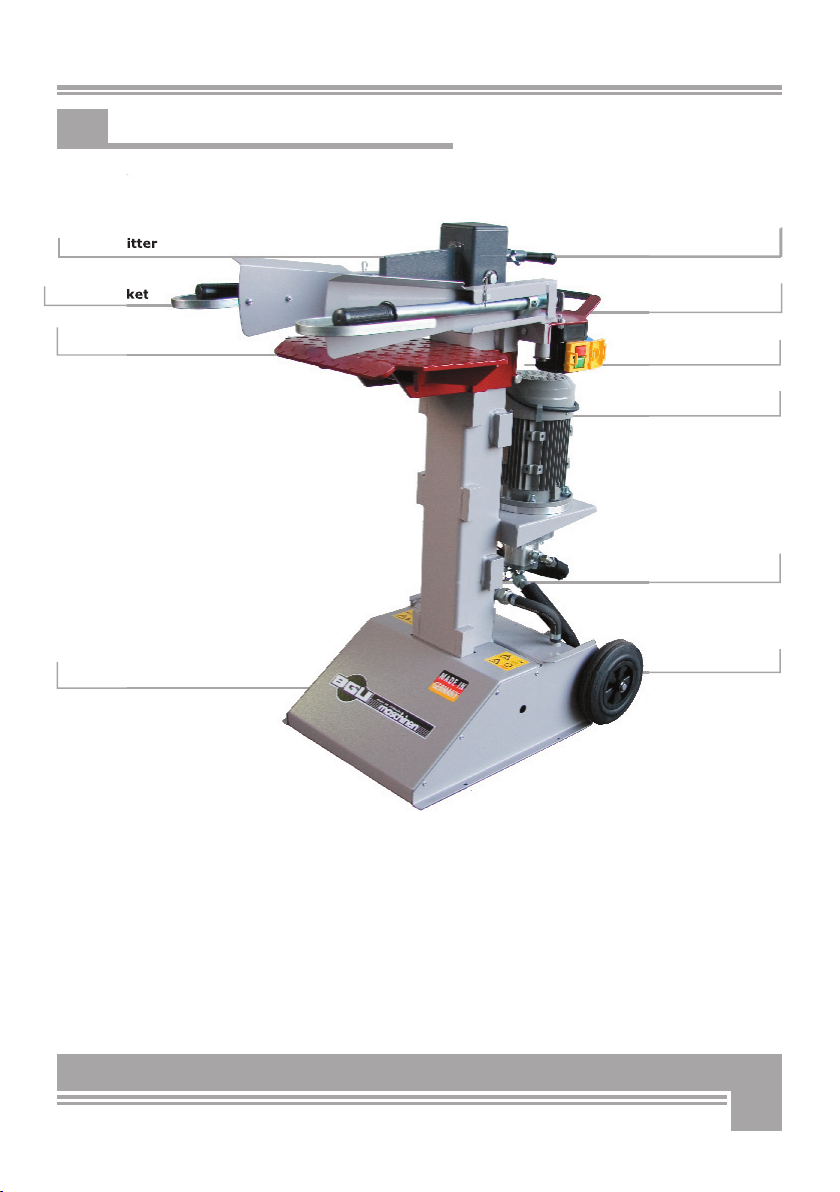
2. PRODUCT OVERVIEW
Operating arms
Wheels
Switches-
Transport handle
Motor
Splitting column
Table
Stand
Guard bracket
Cross splitter
uard bracket
Cross splitter

6
3. WARNING AND SAFETY LABELS
4. "pmax 200 bar" label for 230V
"pmax 220 bar" label for 400V
This label displays the max. operating pressure.

7

8
Servicing, setup, maintenance and cleaning as well as trans-
porting the machine may only be performed with the motor
turned off and machine parts at a standstill.
In order to minimize hazards and avoid damage, it is essential that
the instructions regarding operation, assembly, maintenance, repair,
malfunctions and similar are complied with. Moreover, the machines
may only be operated, maintained and repaired by persons who are
familiar with the machine and who have been instructed regarding the
hazards. Pertinent accident prevention regulations and any general-
ly recognized safety, occupational health and road traffic regulations
must be complied with.
Persons under 18 years of age may not work on splitters. It is permis-
sible, however, to assign such work to persons older than 16 years of
age, as long as this is necessary for the sake of achieving certain trai-
ning objectives and if safety is guaranteed by the supervision of other
skilled personnel.
The work site must be organized and maintained in such a way that
safe working is possible.
The work site must be kept free of obstacles (tripping hazards). Grit/
sand is to be strewn on slippery and slick areas; sawdust and wood
ash are unsuitable for this. The machine must be set up on level, even
and firm ground.
• The work site must be adequately illuminated.
• A level and stable area with adequate freedom of movement is re-
quired for working.
• Work on the electrical system may only be performed by a qualified
electrician.
• The operator of the machine is required to wear personal protective
equipment, safety boots, snugly-fitting clothing, suitable gloves and
protective goggles.
• The log splitter may only be operated if all of the protective guards
installed or intended by the manufacturer are in place.
• Never leave the running machine unattended.
The work site around the log splitter and/or the routes for transpor-
ting wood to and from the machine must be organized and maintained
in such a way that safe working is possible.
4. SAFETY INSTRUCTIONS

9
4.1 Intended use
The log splitter is designed for operation by 1 person. One machi-
ne may never be operated by two or more persons. The „HS 71“ log
splitter is intended solely for splitting firewood into smaller pieces in
the direction of the grain.
When splitting wood, it is essential to ensure that the wood to be split
is placed only on the splitting table‘s checkered plate.
Any other use does not comply with the „intended use.“ The manufac-
turer is not liable for any kind of damage stemming from this; the risk
is borne solely by the user.
In order to rule out hazards and prevent damage, it is essential that
the instructions regarding installation, operation, maintenance, repair
and similar are complied with.
Only pieces of wood with a minimum diameter of 70 mm and a maxi-
mum diameter of 330 mm may be split.
All warranty claims will expire if the machine is used inappro-
priately.
The manufacturer will not be liable for damage to the machine
and for injury to persons caused by improper use.

10
5. BEDIENUNG
Abb. 2
Abb. 1
2
1
3
4
Abb. 3
5.1 Mounting guard brackets
Before using the log splitter the first time, the guard brackets (1)
must be mounted onto the operating arms (see Fig. 1). For transport
reasons these are only pre-mounted to the operating arm with one
screw (2). Fasten the guard bracket (1) to the operating arm with two
screws (2) each (see Fig. 1). Tighten both screws (2) firmly!
5.2 Remarks on the electrical system
At a length of 25 m (three-phase motor 400 V), the power cable must
have a diameter of 2.5 mm². Please note that the log splitter‘s ground
conductor must be connected, otherwise it will not operate.
For 400V motors, the direction of rotation is to be checked by swit-
ching it on and off briefly before beginning work. The direction of ro-
tation must match the arrow on the motor‘s ventilation cover. If the
direction of rotation does not match the arrow on the ventilation co-
ver, it must be changed using the phase switch (see Fig. 2) in the po-
wer cable.
For AC motors (230V). a minimum cable diameter of 2.5 mm² is ne-
cessary for a cable length of a maximum of 10 m.
5.3 Remarks on the hydraulic system
The hydraulic oil tank (see Fig. 3) can be found in the base of the log
splitter. The oil tank (4) is filled with hydraulic oil at the plant. Care
must be taken when the log splitter is tipped far to the back during
transport, because oil can leak out of the filling nozzle (3). Refer to
page 17 for the replacement of hydraulic oil.
At low temperatures the oil in the hydraulic system is still very vis-
cous. Working (splitting) immediately at such temperatures can lead
to damage to the hydraulic system. In order to ensure problem-free
operation of the hydraulic system at low temperatures, the splitter
shouldfirst be run in idle for 10 - 20 min. to allow the hydraulic oil to
warm up.
11
Abb. 5
6
6
5
5
Abb. 4
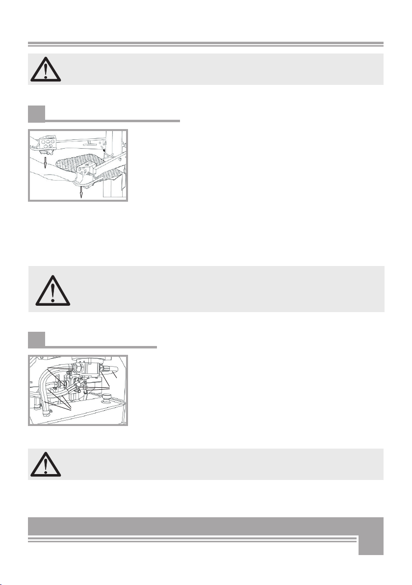
5.4 Checking the two-handed controls
Log splitters are equipped with mechanical two-handed controls. The
purpose of this is to ensure that the operator has no way to reach in-
to the splitting area when working with the machine (see Fig.4). The
two-handed controls should be checked before each use. Both control
levers must be pressed downward to begin the splitting operation. The
splitting wedge travels downward.
Letting go of a control lever will cause the splitting operation to be
halted. The splitting wedge must now remain in its position and may
not return to its initial position.
Letting go of both control levers will cause the splitting wedge to re-
turn to its initial position (at the top).
The splitting wedge is not permitted to travel downward if only one
control lever is actuated. When control levers are released, they must
return automatically to their initial position.
The splitter may not be started up if a malfunction is found in
the two-handed controls (due to mechanical causes such as
bent arms).
5.5 Remarks concerning startup
The log splitter must be checked for external damage each time be-
fore it is started.
The hydraulic hoses (5) and all connection points (6) on the hydraulic
system must be inspected to detect any potentially leakage and to eli-
minate them (see Fig. 5).
All safety systems/guards must be mounted on the machine. They
may not be removed or disabled. If malfunctions or defects become
evident, the machine may not be started up until they have been rec-
tified.
The machine may not be started if the hydraulic system shows
leakage.
The control valve is set at the manufacturing plant; further ad-
justments may not be attempted.
12
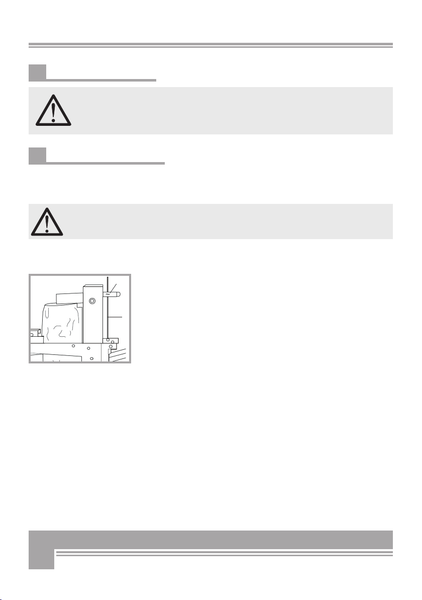
Proceed as follows to modify the lift-height of the splitting wedge:
Move the splitting wedge to the desired height. Pressing on a control
arm causes the splitting column to remain at the desired height. Now
shut off the motor. The splitting column remains at the desired height.
Now loosen the wing bolt (7) at the handle (behind the splitting co-
lumn) and pull the control rod (8) out as far as possible. Use the wing
bolt (7) to clamp the control rod (8) at the desired height, and then
tighten the wing bolt firmly.
Now the log splitter can be switched on again. Now the splitting
wedge cannot extend to its maximum length anymore, because it is
limited by the control rod (8).
To reset the maximum splitting length, it is necessary to loosen the
wing bolt (7). Now the splitting wedge can extend to its maximum
length again. After that tighten the wing bolt (7) firmly again.
Abb. 6
8
7
5.6 Remarks concerning safety
The log splitter must be set up on a firm and even surface. The
work site must be kept free of wood scraps and obstacles (trip-
ping hazards). Grit/sand is to be strewn on slippery and slick
areas. Never reach into the splitting area when the splitting
wedge moves.
5.7 Adjusting the splitting length
When the log splitter leaves the factory, it is set to its maximum split-
ting length. When the motor is switched on, the splitting wedge travels
automatically to its maximum height.
The lift can be limited in cases where it is necessary to split wood
whose height is clearly below the maximum lift of the log split-
ter. The lift height can be adjusted to any level..

13
The bolt is then to be inserted in the existing holes of the table holder
and secured with the wing nut (11; Fig. 9).
(It is only possible to insert the bolt in the holes if the table was
mounted properly.)
At the bottom holder, the table can be mounted only without the se-
curing bolt (valve is in the way). Take particular care to ensure here
that the hooks on the back of the table latch in behind the holders
above them.
Abb. 9
11
9
Abb. 7
Abb. 8
10
5.8 Adjusting the table
Logs ranging from 550 mm to 1065 mm can be easily split by adjus-
ting the splitting table. The table can be adjusted to three heights, wi-
thout the need for tools.
To adjust the table, unscrew the wing nut (9; Fig.7) on the table
mount/column and remove the bolt from the hole. Now the table (10;
Fig. 8) can be easily raised and removed by pulling it forward.
To mount the table (10; Fig. 8), it must again be slightly raised at
the front. Place the table on the holders on the stand at the height
that matches the wood you are splitting, and slide it to the back in a
tipped-up position. Lower the table at the front, and ensure that the
hooks on the back of the table latch in behind the upper holders.

14
Abb. 10
12
13
B
B
A
5.9 Working with the wood clamps
Wood clamps (12) are attached to the operating arms to hold wood in
place during the splitting operation (see Fig. 10).
Because of the attached pressure springs (13), the wood clamps can
adapt variably to logs of any size (see Fig. 10).
The log must be aligned centrally in the wood clamps to ensure opti-
mum functionality and proper splitting.
5.10 Working with the log splitter
Place the wood to be split on the splitting table and press both opera-
ting arms (A) inwards (see Fig. 10). This will fix the wood in place.
Both control levers must be pressed downward (B) simultaneously to
begin the splitting operation. This will set the splitting wedge in moti-
on.
Both control levers (B) must be pressed during the entire splitting ope-
ration.
Release the control levers to cancel the splitting operation. The split-
ting wedge will travel back to its initial position. Once the splitting
operation is finished, release both control levers so that the splitting
wedge can travel back to the top (B).
The split wood may only be removed from the splitting table after the
splitting wedge is back in its initial position.
If necessary, clear the wood scraps and chips from the table before be-
ginning the next splitting operation.
Ensure that the wood to be split is always placed on the table
straight. Note that wood that is full of branches can splinter. Never
use any wood that has not had its branches removed.
5.11 Releasing jammed pieces of wood
Sometimes the wood is not completely split through and it is pulled
upward by the splitting wedge as it travels to the top. If this happens,
allow the splitting wedge to travel back to its initial position, and then
switch off the log splitter. Now the wood must be knocked away. This
can be accomplished with a hammer.

15
On electrically-powered machines, always remove the power
plug before changing locations.
It is very easy to transport the log splitter. An axle with two wheels is
attached at the back.
To transport the log splitter, tip it backward slightly until the wheels
are touching the ground (see Fig.11).
The motor guard can also serve as a handle.
There is a transport handle situated near the top of the splitting co-
lumn.
When transporting the splitter, it is advisable to drive the splitting
wedge right to the bottom.
The two control levers should be bound together at the front so that
they do not accidentally swivel around during transport.
6. TRANSPORTING THE MACHINE
Abb. 11

16
Available as accessories* for our log splitters are a cross splitter and
a splitting wedge expander (as additional purchases).
The cross splitter splits the firewood into 4 parts in one operation. The
splitting wedge expander allows improved and faster splitting of the
wood.
Both accessory parts are simply slid onto the splitting wedge and
clamped in place with a star-shaped knob (M12).
When mounting the cross splitter, ensure that the inclined side of the
crosswise blade is facing the operator.
Splitting wedge expander: Item No. 90303
Cross splitter: Item No. 90302
Ensure that the cross splitter and the splitting wedge expan-
der are fully slid onto the splitting wedge and secured in place
with the screw.
If the cross splitter or the splitting wedge expander are not complete-
ly slid onto the splitting wedge, they can slip forward during operation
and injure the person operating the machine. It is also possible that
the machine becomes damaged.
If possible, the cross splitter should not be used for hardwood (fruit
trees, beech), because this kind of wood presents the cross splitter
with much more resistance and is more likely to trigger the pressure
relief valve in the hydraulic system and cause the wood to jam.
The diameter of the wood must be a minimum of 200 mm if the
cross splitter is used, otherwise the log splitter could be dama-
ged. Moreover, the wood clamps must be secured in the positi-
on furthest to the back using a cotter pin.
* Accessory parts are not included in the basic equipment and are available at
additional cost.
7. CROSS SPLITTER AND SPLITTING WEDGE
EXPANDER AS ACCESSORIES
Abb. 12

17
8. MAINTENANCE AND
SERVICING WORK
Please perform maintenance, servicing and cleaning only
after the machine has been turned off (pull plug out of so-
cket) and machine parts are at a standstill.
8.1 Regular maintenance tasks
The following tasks are to be performed as necessary and/or on a re-
gular basis:
• Clean away wood scraps, wood chips and any other dirt from the
machine
• Grease the splitting column
• Check the level of the hydraulic oil; if there is a loss of oil then
check the leak-tightness of the entire hydraulic system (hoses and
screw connections)
• Lubricate all moving parts
8.2 Remarks regarding the hydraulic
Check the level of the hydraulic oil regularly. Ensure that no dirt or
wood chips have found their way into the oil tank.
Never run the splitter without or with insufficient oil. If a lack of oil
causes air to enter the circulation system, the splitter will begin to
work incorrectly (jerking and erratic), and the hydraulic pump can be
damaged.
The first oil change must be performed after approx. 25-30 hours of
operation. After that the hydraulic oil is to be changed approx. every
50 hours of operation or at least once a year.
The drain screw can be found on the underside of the oil tank. The fil-
ler screw can be found on the upper right of the tank.
Recommended hydraulic oils: - HLP 46,
DEA HD B 46, Shell Tellus 10-46, Esso Nuto H 46
When changing the oil be sure to collect the old oil in a suitable con-
tainer. Ensure that the container you use is oil-resistant and has a
minimum capacity of 7 liters. If the container is smaller, you can drain
the oil in multiple stages.
Old oil is harmful to the environment and must be properly dis-
posed of.
After filling the oil tank, run the log splitter three to four times to al-
low air to escape out of the hydraulic circulation system; then replace
the tank cap.

18
8.3 Guides in the splitting column
If squeaking sounds can be heard while running the log splitter, it
is necessary to grease the polyamide guides in the splitting column
tracks. A standard commercially-available grease can be used for this.
The squeaking sounds should cease after doing this.
After the polyamide guides have worn out, if the splitting column be-
gins showing signs of excessive play to the column tracks, the polya-
mide guides must be replaced.
8.4 Wear parts
• Item No. 53057 Top guide
• Item No. 53058 Bottom guide

19
When the machine has reached a condition that it cannot be used
anymore and must be scrapped, it is necessary to deactivate and dis-
mantle it. This means that it must be converted into a state in which it
cannot be used anymore for the purpose for which it was constructed.
In the scrapping process the recycling of the machine‘s basic materi-
als must be kept in mind.
These materials may potentially be reusable in a recycling process.
The manufacturing company assumes no responsibility for potential
injury to persons or damage to property that stem from the re-use of
machine parts, if these parts are used for purposes other than those
for which they were originally intended.
Deactivation of the machine:
All deactivation or scrapping work must be performed by persons who
were trained for this.
● Block each movable machine part and dismantle the machine down
to its individual parts
● Send all components to controlled disposal facilities
● Drain fuel out of the tank and dispose of it in an environmentally
friendly way
● Remove rubber parts from the machine and bring them to a facility
that takes them
No residual risk exists anymore after all movable parts have been
deactivated and blocked.
Electrical components are considered special/hazardous waste and
must be disposed of separate from the machine. If a fire occurs in the
electrical systems of the machine, fire extinguishing equipment is to
be used that is certified for this purpose (e.g. powder extinguishers).
9. DECOMMISSIONING AND DISPOSAL

20
10. TECHNICAL SPECIFICATIONS
*Splitting force can fluctuate by ± 10%.
10.1 Noise emissions
The noise emissions were determined as guide in compliance with the
general rules for assessing the noise emitted by technical equipment
for agricultural and forestry at the work site as well as the general in-
structions for measuring the noise emitted by technical equipment for
agricultural and forestry, with the following parameters:
Measurement point at the front edge of the machine, 1600 mm high,
1000 mm ahead of the machine
Max. noise emission, idle: 75 dB(A)
Max. noise emission, full throttle: 80 dB
Technical specifications Unit 230 V 400 V
Splitting height mm 550/750/1065 550/750/1065
Ram stroke mm 500 500
Min. wood diameter mm 70 70
Max. wood diameter mm 330 330
Splitting force* t 6 7
Max. operating pressure bar 200 220
Motor power rating P1 kW 2,2 3,0
Nominal current A 13,1 4,8
Speed RPM 2660 2840
Rated voltage V 230 400
Backup fuse A 16
Total height, extendet mm 1570 1570
Total height, retracted mm 1100 1100
Width mm 570 570
Depth mm 940 940
Weight kg 132 126
Oil capacity (tank/system) l 5,0 5,0
Table of contents
Other BGU Log Splitter manuals


Popular Log Splitter manuals by other brands


Scheppach
Scheppach HL800VARIO Translation from the original instruction manual

Scheppach
Scheppach HL1800GM Translation from the original instruction manual

Mr.Paldu
Mr.Paldu Horizontalspalter 550 operating instructions

Scheppach
Scheppach HL1600 Translation of original instruction manual

Homelite
Homelite UT49103 Operator's manual

Craftsman
Craftsman 247.77640 Operator's manual


