Boston Harbor 7288129 Owner's manual

READ AND SAVE THESE INSTRUCTIONS
CEILING FAN INSTALLATION AND
OPERATION INSTRUCTION
FAN RATING AC 120V. 60Hz
SKU# 7288129
1
1. SAFETY RULES
1. To reduce the risk of electric shock, insure
electricity has been turned off at the circuit
breaker or fuse box before beginning.
2. All wiring must be in accordance with the
National Electrical Code and local
electrical codes. Electrical installation
should be performed by a qualified
licensed electrician.
3. WARNING: To reduce the risk of electrical
shock and fire, do not use this fan with any
solid-state fan speed control device.
4. WARNING: To reduce the risk of personal
injury, use only the two steel screws (and
lock washers) provided with the outlet box
for mounting to the outlet box. Most outlet
boxes commonly used for the support of
lighting fixtures are not acceptable for fan
support and may need to be replaced,
consult a qualified electrician if in doubt.
5. The outlet box and support structure must
be securely mounted and capable of
reliably supporting a minimum of 50
pounds. Use only CUL Listed outlet boxes
marked FOR FAN SUPPORT.
6. The fan must be mounted with a minimum
of 7 feet clearance from the trailing edge of
the blades to the floor.
7. Do not operate the reverse switch while
the fan blades are in motion. The fan must
be turned off and the blades stopped
before reversing the blades direction.
8. Avoid placing objects in the path of the
blades.
9. To avoid personal injury or damage to the
fan and other items, be cautious when
working around or cleaning the fan.
10. Do not use water or detergents when
cleaning the fan or fan blades. A dry
dust cloth or lightly dampened cloth will
be suitable for most cleaning.
11. After making electrical connections,
spliced conductors should be turned
upward and pushed carefully up into the
outlet box. The wires should be spread
apart with the grounded conductor and
the equipment-grounding conductor on
one side of the outlet box.
12. Electrical diagrams are for reference only.
Light kits that are not packed with the fan
must be CUL Listed and marked suitable
for use with the model fan you are
installing. Switches must be CUL
General Use Switches. Refer to the
Instructions packaged with the light kits
and switches for proper assembly.
WARNING
TO REDUCE THE RISK OF FIRE,
ELECTRIC SHOCK OR PERSONAL
INJURY, MOUNT FAN TO OUTLET BOX
MARKED ACCEPTABLE FOR FAN
SUPPORT.
WARNING
TO REDUCE THE RISK OF PERSONAL
INJURY, DO NOT BEND THE BLADE
ARMS (ALSO REFERRED TO AS
BRACKETS) DURING ASSEMBLY OR
AFTER INSTALLATION. DO NOT INSERT
OBJECTS IN THE PATH OF THE BLADES.
ATTENTION
Under the Energy Policy Act of 2005,
federal regulations require all ceiling fans
with light kits manufactured or imported
after January 1, 2009, to limit the total
wattage consumed by the light kit to 190
watts. Therefore, this product is equipped
with a 190W limiting device. If lamping
exceeds 190 watts, the light kit will shut off
automatically until the proper wattage of
bulbs are installed. Reset the light kit by
turning it off, replacing the bulbs with the
correct wattage, and then turning the light
kit back on.
NOTE
READ AND SAVE ALL INSTRUCTIONS!
a
b
c
d
e
f
g
h
i
j
m
l
k
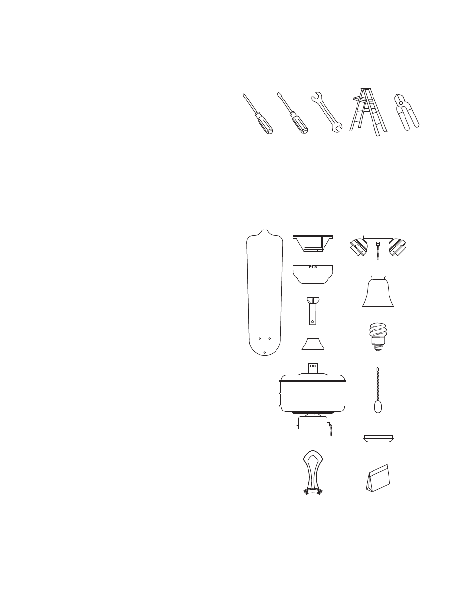
3. PACKAGE CONTENTS
Unpack your fan and check the contents. You
should have the following items:
a. Blade set (5)
b. Hanger bracket
c. Canopy
d. Downrod
e. Coupling cover
f. Fan motor assembly
g. Set of blade brackets (5)
h. Light kit
i. Glass shades (3)
j. 13 Watt compact fluorescent bulbs (3)
k. Pull chains and fobs (2)
l. Extra switch housing cover
m. Package hardware
1) Mounting hardware:
wood screws (2), lock washers (2),
wire nuts (3)
2) Blade attachment hardware:
screws (16), fibber washers (16)
3) Blade bracket attachment hardware:
gaskets (5)
4) Close-to-ceiling hardware:
screws with lock washers (3)
5) Light kit hardware:
screws (1)
6) Safety cable hardware:
wood screws, lock washer,
metal washer
7) Balance Kit
2
2. TOOLS AND MATERIALS
REQUIRED
●Philips screw driver
●Blade screw driver
●Adjustable wrench
●Step ladder
●Electrical tape & wire cutters
3
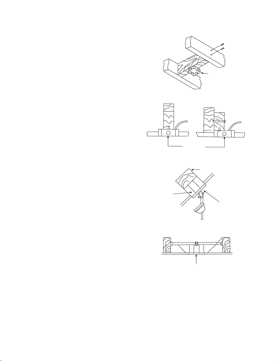
4. MOUNTING OPTIONS
If there isn't an existing CUL listed mounting
box, then read the following instructions.
Disconnect the power by removing fuses or
turning off circuit breakers.
Secure the outlet box directly to the building
structure. Use appropriate fasteners and
building materials. The outlet box and its
support must be able to fully support the
moving weight of the fan (at least 50 lbs). Do
not use plastic outlet boxes.
Figures 1, 2 and 3 are examples of different
ways to mount the outlet box.
Note: You may need a longer downrod to
maintain proper blade clearance when
installing on a steep, sloped ceiling. (Fig. 3)
To hang your fan where there is an existing
fixture but no ceiling joist, you may need an
installation hanger bar as shown in Figure 4.
Outlet box
Provide strong support
Recessed
outlet box
Ceiling
mounting
bracket
Outlet box
Figure 1
Figure 3
Figure 4
Outlet box
Figure 2
Angled ceiling
maximum
20° angle

Figure 7
4
5. HANGING THE FAN
REMEMBER to turn off the power. Follow the
steps below to hang your fan properly.
NOTE: This ceiling fan is supplied with two types of
hanging assemblies; the standard ceiling
installation using the downrod with ball and socket
mounting and the "close-to-ceiling" installation.
The "close-to-ceiling" installation is recommended
in rooms with less than 8-foot ceilings or in areas
where additional space is desired from the floor to
the fan blades. Once you have selected which
mounting system you will use, proceed with the
following instructions. Where necessary, each
section of the instructions will note the different
procedures to follow for the two types of mounting.
STANDARD CEILING
INSTALLATION
1. Pass the 120-volt supply wires through the
center hole in the ceiling hanger bracket as shown
in Fig. 5.
2. Secure the hanger bracket to the ceiling outlet
box using screws and lock washers included with
your outlet box. (Fig. 5)
3. Remove the hanger pin, lock pin and set screws
from the top of the motor assembly.
4. Route wires exiting from the top of the fan motor
through the coupling cover, canopy and then
through the ball/ downrod. (Fig. 6)
5. Align the holes at the bottom of the downrod with
the holes in the collar on top of the motor housing
(Fig. 6). Carefully insert the hanger pin through the
holes in the collar and downrod. Be careful not to
jam the pin against the wiring inside the downrod.
Insert the locking pin through the hole in locked
position, as noted in the circle inset of Figure 6.
WARNING: FAILURE TO PROPERLY INSTALL
LOCKING PIN AS NOTED IN STEP 5 COULD
RESULT IN FAN LOOSENING AND POSSIBLY
FALLING.
6. Tighten two set screws on top of the fan motor
firmly. (Fig. 6)
7. Place the downrod ball into the hanger bracket
socket. (Fig. 7)
INSTALLATION OF SAFETY SUPPORT
An additional safety support is provided to prevent
the fan from falling. Secure the safety cable to the
ceiling joist with screw and washer, as illustrated in
Figure 8.
Figure 5
Figure 6
Figure 7
Figure 8
Tab
Mounting screws
(supplied with
electrical box)
CUL Listed
electrical
box
Hanger bracket
Hanger bracket
Safety cable
Registration slot
Ball/downrod
assembly
Ceiling canopy
Motor wires
Locking pinHanger pin
Tighten screws
firmly
Coupling cover
Table of contents
Other Boston Harbor Fan manuals


Popular Fan manuals by other brands


Harbor Breeze
Harbor Breeze RLG52NWZ5L manual

Allen + Roth
Allen + Roth L1405 instruction manual

ViM
ViM KUBAIR F400 ECOWATT Technical manual

HIDRIA
HIDRIA R10R-56LPS-ES50B-04C10 user guide

BLAUBERG Ventilatoren
BLAUBERG Ventilatoren CENTRO-M 100 L user manual

Triangle Engineering
Triangle Engineering HEAT BUSTER SPL Series owner's manual