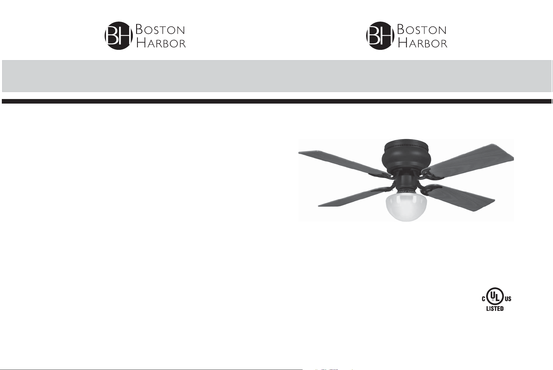
Boston Harbor 1038694 Owner's manual
READ AND SAVE THESE INSTRUCTIONS
CEILING FAN INSTALLATION AND
OPERATION INSTRUCTION
FAN RATING AC 120V. 60Hz
SKU# 1038694

1
1. SAFETY RULES
1. To reduce the risk of electric shock, insure
electricity has been turned off at the circuit
breaker or fuse box before beginning.
2. All wiring must be in accordance with the
National Electrical Code and local
electrical codes. Electrical installation
should be performed by a qualified,
licensed electrician.
3. WARNING: To reduce the risk of electrical
shock and fire, do not use this fan with any
solid-state fan speed control device.
4. WARNING: To reduce the risk of personal
injury, use only the two steel screws (and
lock washers) provided with the outlet box
for mounting to the outlet box. Most outlet
boxes commonly used for the support of
lighting fixtures are not acceptable for fan
support and may need to be replaced. If in
doubt, consult a qualified electrician.
5. The outlet box and support structure must
be securely mounted and capable of
reliably supporting a minimum of 50
pounds. Use only CUL Listed outlet boxes
marked FOR FAN SUPPORT.
6. The fan must be mounted with a minimum
of 7 feet clearance from the trailing edge of
the blades to the floor.
7. Do not operate the reverse switch while
the fan blades are in motion. The fan must
be turned off and the blades stopped
before reversing the blade direction.
8. Avoid placing objects in the path of the
blades.
9. To avoid personal injury or damage to the
fan and other items, be cautious when
working or cleaning around the fan.
10. Do not use water or detergents when
cleaning the fan or fan blades. A dry
dust cloth or lightly dampened cloth will
be suitable for most cleaning.
11. After making electrical connections,
spliced conductors should be turned
upward and pushed carefully up into the
outlet box. The wires should be spread
apart with the grounded conductor and
the equipment-grounding conductor on
one side of the outlet box.
12. Electrical diagrams are for reference only.
Light kits that are not packed with the fan
must be CUL Listed and marked suitable
for use with the model fan you are
installing. Switches must be CUL
General Use Switches. Refer to the
Instructions packaged with the light kits
and switches for proper assembly.
WARNING
TO REDUCE THE RISK OF FIRE,
ELECTRIC SHOCK OR PERSONAL
INJURY, MOUNT FAN TO OUTLET BOX
MARKED ACCEPTABLE FOR FAN
SUPPORT.
WARNING
TO REDUCE THE RISK OF PERSONAL
INJURY, DO NOT BEND THE BLADE
ARMS (ALSO REFERRED TO AS
BRACKETS) DURING ASSEMBLY OR
AFTER INSTALLATION. DO NOT INSERT
OBJECTS IN THE PATH OF THE BLADES.
ATTENTION
Under the Energy Policy Act of 2005,
federal regulations require all ceiling fans
with light kits manufactured or imported
after January 1, 2009, to limit the total
wattage consumed by the light kit to 190
watts. Therefore, this product is equipped
with a 190W limiting device. If lamping
exceeds 190 watts, the light kit will shut off
automatically until the proper wattage of
bulbs are installed. Reset the light kit by
turning it off, replacing the bulbs with the
correct wattage, and then turning the light
kit back on.
NOTE
READ AND SAVE ALL INSTRUCTIONS!
2
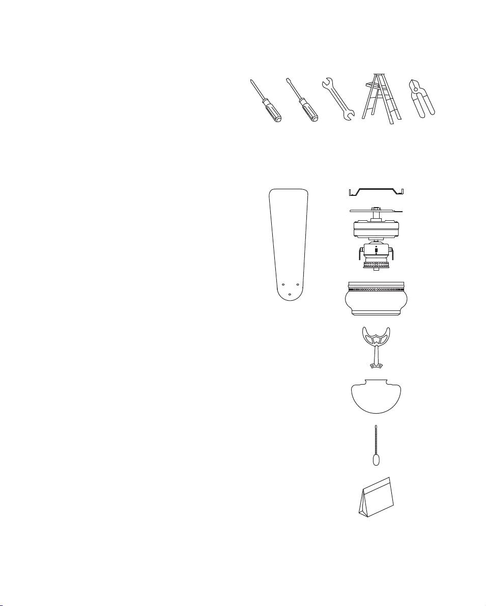
3. PACKAGE CONTENTS
Unpack your fan and check the contents. You
should have the following items:
a. Blade set (4)
b. Ceiling mounting plate
c. Fan motor assembly
d. Motor housing
e. Set of blade brackets (4)
f. Glass shade
g. Pull chain and fobs (2)
h. Package hardware
1) Mounting hardware:
wood screws (2), lock washers (2),
wire nuts (3)
2) Blade attachment hardware:
screws (13), fiber washers (13)
3) Light kit hardware:
(1 screw)
4) Mounting hardware
(5 screws)
5) Safety cable hardware:
wood screws, lock washer,
metal washer
6) Balance kit
ab
c
d
e
f
h
g
2. TOOLS AND MATERIALS
REQUIRED
●Philips screw driver
●Blade screw driver
●Adjustable wrench
●Step ladder
●Electrical tape & wire cutters
3
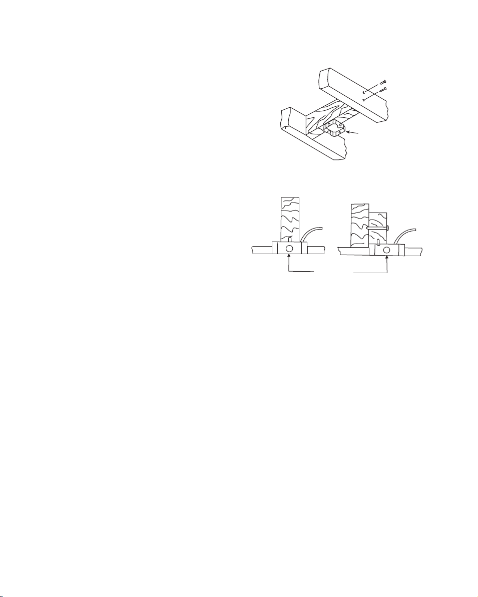
4. INSTALLING YOUR FAN
Mounting Options
If there isn't an existing UL listed mounting
box, then read the following instructions.
Disconnect the power by removing fuses or
turning off circuit breakers.
Secure the outlet box directly to the building
structure. Use appropriate fasteners and
building materials. The outlet box and its
support must be able to fully support the
moving weight of the fan (at least 50 lbs). Do
not use plastic outlet boxes.
Figures 1 and 2 are examples of different
ways to mount the outlet box.
Outlet box
Figure 1
Outlet box
Figure 2
4
5. HANGING THE FAN
REMEMBER to turn off the power. Follow the
steps below to hang your fan properly.
1. Attach the ceiling mounting plate to the
outlet box using the two screws and washers
provided with the outlet box.(Fig. 3). For best
performance be sure the mounting plate is
level and secured firmly against the ceiling.
You may need to insert additional washers
(not provided) between the outlet box and
mounting plate to make it level.
2. Carefully Lift the fan motor assembly
(without the blades) and insert the T section
of the motor housing plate into the slot in the
ceiling mounting plate as shown in Fig. 4.
INSTALLATION OF SAFETY SUPPORT
An additional safety support is provided to
prevent the fan from falling. Secure the safety
cable to the ceiling joist with screw and
washer, as illustrated in Figure 4.
You are now ready to make the electrical
connections.
Figure 3
Figure 4
Screws
Outlet box
Ceiling
mounting
plate
Motor
assembly
Slot
Safety Cable
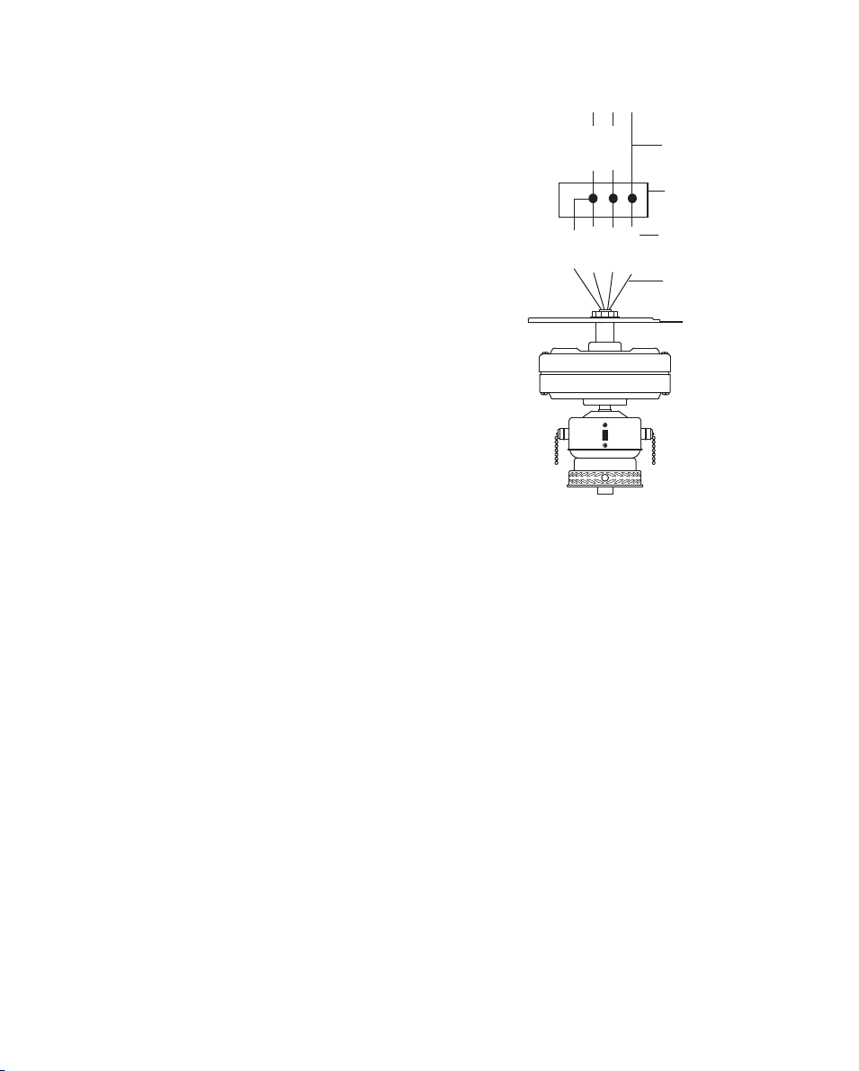
5
Figure 5
6. MAKE THE ELECTRIC
CONNECTIONS
Remember to disconnect the power.
Follow the steps below to connect the fan to
your household wiring. Use the wire
connecting nuts supplied with your fan.
Secure the connectors with electrical tape.
Make sure there are no loose strands or
connections.
Step 1. Connect the fan supply (black) wire
and light supply (blue) wire to the black
household supply wire as shown in Figure 5.
Step 2. Connect the neutral fan (white) wire
to the white neutral household wire.
Step 3. Connect the fan ground wire (green)
to the household ground wire.
Step 4. After connecting the wires, spread
them apart so that the green and white wires
are on one side of the outlet box and the
black and the blue wires are on the other
side.
Step 5. Turn the connecting nuts upward and
push the wiring into the outlet box.
WARNING: TO REDUCE THE RISK OF
FIRE, ELECTRIC SHOCK, OR OTHER
PERSONAL INJURY, MOUNT FAN ONLY
ON AN OUTLET BOX OR SUPPORTING
SYSTEM MARKED ACCEPTABLE FOR FAN
SUPPORT. TO REDUCE THE RISK OF
FIRE OR ELECTRIC SHOCK, DO NOT USE
THIS FAN WITH ANY SOLID-STATE SPEED
CONTROL DEVICE.
WIRING BOX
GROUND TO
MOUNTING
BRACKET
GREEN GROUND
GREEN GROUND
SUPPLY CIRCUIT
BLACKBLACK
WHITEWHITE
BLUE
GREEN
6
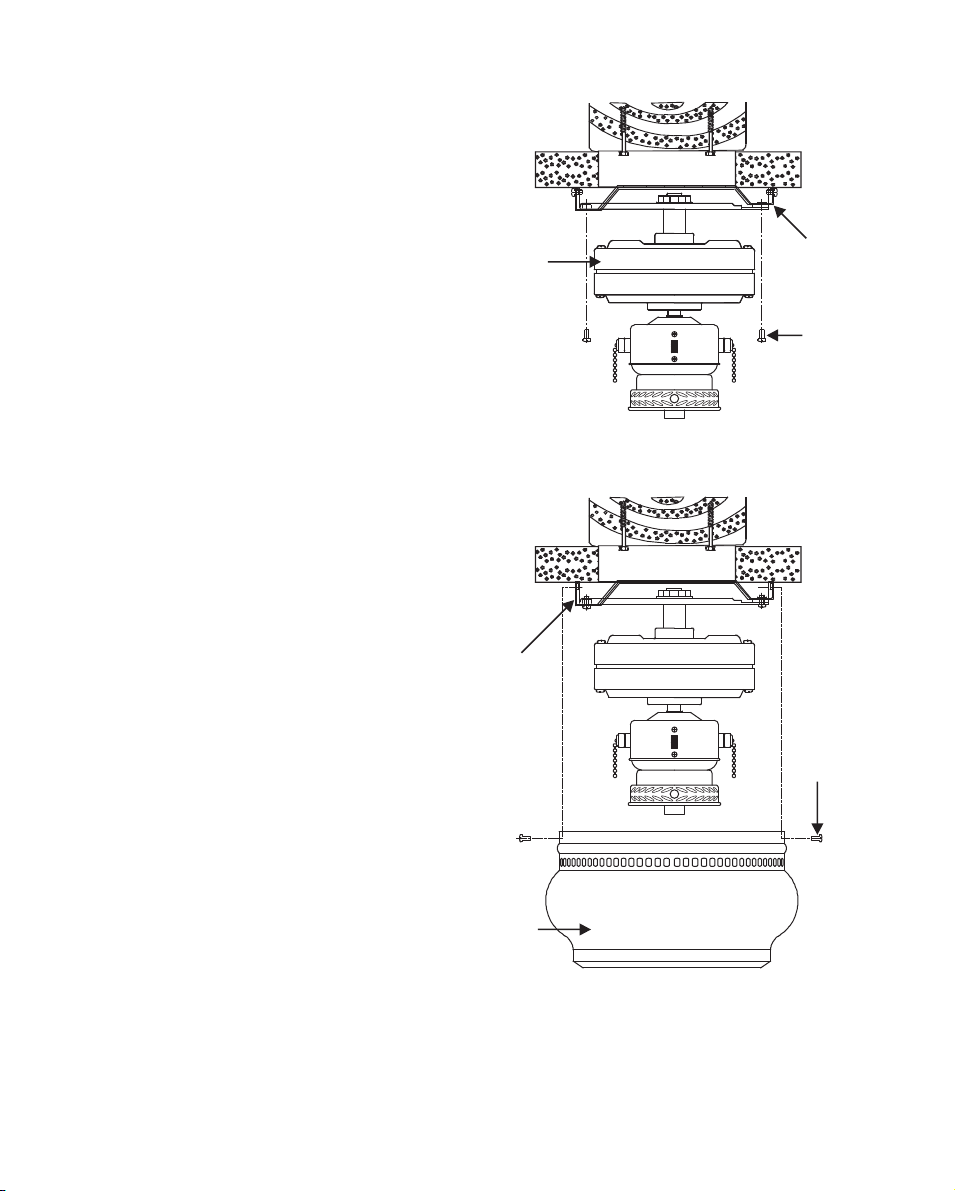
Figure 6
Figure 7
7. FINISHING THE
INSTALLATION
1. Swing the motor assembly up into position
under the ceiling mounting plate. Secure the
hanger bracket to the mounting plate with the
screws provided. (Fig. 6)
2. Carefully lift the motor housing onto the
ceiling mounting plate, properly align the
holes, and tighten the motor housing with the
4 screws supplied. (Fig. 7)
Ceiling
Moumting
plate
Ceiling
Moumting
plate
Screws
Motor
Motor
housing
Screws

7
Figure 9
Figure 8
Figure 10
8. ATTACHING THE FAN
BLADES
Step 1. Attach the blades to the blade arms
using the screws and fiber washers provided
as shown in Figure 8. Insert a screw into the
arm,, but do not tighten. Repeat for the other
2 screws and washers.
Step 2. Tighten each screw securely starting
with the center screw. Make sure the blade is
straight.
Step 3. Fasten blade assemblies to the motor
using the screws already installed in the
motor housing. (Fig. 9)
All blades are grouped by weight. Because
natural woods vary in density, the fan may
wobble even though the blades are weighed
equally.
The following procedure should correct most
fan wobbling problems. Check after each
step.
1. Check that all blade and blade arm screws
are secure.
2. Most fan wobbling problems are caused
when blade levels are unequal. Check this
level by selecting a point on the ceiling
above the tip of one of the blades.
Measure this distance as shown in Figure
10. Rotate the fan until the next blade is
positioned for measurement. Repeat for
each blade. The distance deviation should
be within 1/8". (Fig.10)
3. Use the enclosed blade balancing kit if the
blade wobble is still noticeable.
4. If the blade wobble is still noticeable,
interchanging two adjacent (side by side)
blades can redistribute the weight and
WARNING
TO REDUCE THE RISK OF PERSONAL
INJURY, DO NOT BEND THE BLADE
ARM WHILE INSTALLING/BALANCING
THE BLADES OR WHEN CLEANING
THE FAN. DO NOT INSERT FOREIGN
OBJECTS BETWEEN ROTATING FAN
BLADES.
Touching
ceiling
Blade
Screws and
Fiber washers
Blade arm
Blade assembly
Screws
Motor
8
Figure 11
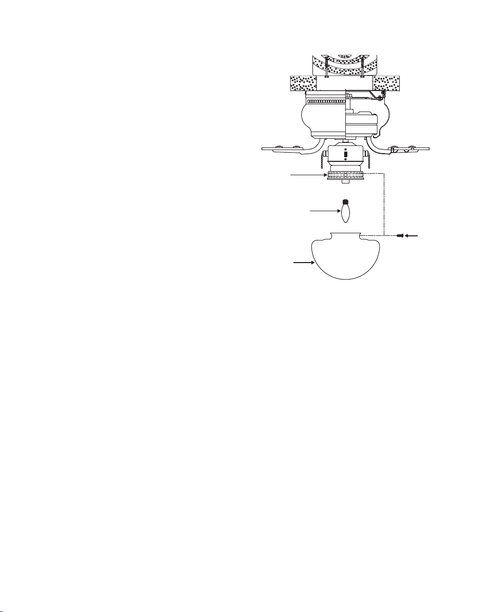
9. INSTALLING THE LIGHT
KIT
NOTE: Before starting installation, disconnect
the power by turning off the circuit breaker or
removing the fuse in the fuse box. Turning
power off using the fan switch is not sufficient
to prevent electric shock.
1. Install 1 X 60W max. E12 base candelabra
bulb (not included).
2. Mount the glass shade to the light fixture
by partially unscrewing the thumb screws,
inserting the glass shade, and then gently
tightening the thumb screws until the glass
shade is secure. Do not over tighten. (Fig.
11)
3. Restore power and your light kit will be
ready for operation.
Glass shade
Thumb
screws
Light kit
assembly
Bulb

9
Figure 12
Figure 13
Turn on the power and check the operation of
your fan. There are two pull chains available
in your fan:
1. 3-speed pull chain- it controls the fan
speed as follows:
1-Pull = High Speed
2-Pulls = Medium Speed
3-Pulls = Low Speed
4-Pulls = Fan Off
Speed settings for warm or cool weather
depend on factors such as the room size,
ceiling height, number of fans, and so on.
2. Light kit pull chain- it controls the light kit in
"ON" or "OFF".
The slide switch controls directions: forward
(switch down) or reverse (switch up).
Warm weather - (Counter-Clockwise
direction) A downward airflow creates a
cooling effect as shown in Figure 12. This
allows you to set your air conditioner on a
higher setting without affecting your comfort.
Cool weather - (Clockwise direction) An
upward airflow moves warm air off the ceiling
area as shown in Figure 13. This allows you
to set your heating unit on a lower setting
without affecting your comfort.
NOTE
WAIT FOR FAN TO STOP BEFORE
CHANGING THE SETTING OF THE
SLIDE SWITCH.
10. OPERATING YOUR FAN
10
IMPORTANT
MAKE SURE THE POWER IS OFF AT THE ELECTRICAL PANEL BOX BEFORE YOU
ATTEMPT ANY REPAIRS. REFER TO THE SECTION "MAKING ELECTRICAL
CONNECTIONS".
Here are some suggestions to help you maintain your fan
1. Because of the fan's natural movement, some connections may become loose. Check the
support connections, brackets, and blade attachments twice a year. Make sure they are
secure. (It is not necessary to remove fan from ceiling.)
2. Clean your fan periodically to help maintain its new appearance over the years. Use only a
soft brush or lint-free cloth to avoid scratching the finish. The plating is sealed with a lacquer to
minimize discoloration or tarnishing. Do not use water when cleaning. This could damage the
motor, or the wood, or possibly cause an electrical shock.
3. You can apply a light coat of furniture polish to the wood blades for additional protection and
enhanced beauty. Cover small scratches with a light application of shoe polish.
4. There is no need to oil your fan. The motor has permanently lubricated bearings.
Problem
Fan will not start.
Fan sounds
noisy.
Lights shut off
and will not come
back on.
Solution
1. Check circuit fuses or breakers.
2. Check line wire connections to the fan and switch wire connections in the
switch housing. CAUTION: Make sure main power is off.
1. Make sure all motor housing screws are snug.
2. Make sure the screws that attach the fan blade brackets to the motor hub
are tight.
3. Make sure wire nut connections are not rubbing against each other or the
interior wall of the switch housing. CAUTION: Make sure main power is off.
4. Allow a 24-hour "breaking-in" period. Most noise associated with a new fan
disappear during this time.
5. If using an optional light kit, make sure the screws securing the glassware
are tight. Check that light bulb is also secure.
6. Some fan motors are sensitive to signals from solid-state variable speed
controls. If you have installed this type of control, choose and install
another type of control.
7. Make sure the upper canopy is a short distance from the ceiling. It should
not touch the ceiling.
1. This unit is equipped with a wattage limiting device. Lamping in excess of
190 watts will disable your ceiling fan's light kit. To reset your light kit you
must turn the power off and re lamp, keeping the wattage under 190 watts.
Restore power to your ceiling fan and continue normal operation.
12. TROUBLESHOOTING
11. CARE OF YOUR FAN

Boston Harbor Fans warrants this fan to be free from defects in workmanship and
material present at time of shipment from the factory for 30 years from the date of
purchase. This warranty applies only to the original purchaser. Boston Harbor agrees to
correct such defect at no charge or at our option replace the ceiling fan with a
comparable or superior model.
To obtain warranty service or replacement fan, return the fan to place of purchase,
along with original sales receipt. All cost of removal and reinstallation are the
expressed responsibility of the purchaser. Any damage to the ceiling fan by accident,
misuse or improper installation, or by affixing accessories not produced by this
warranty, are at the purchaser' s own responsibility. Boston Harbor assumes no
responsibility whatsoever for fan installation during the 30-year warranty.
Any service performed by an unauthorized person will render the warranty invalid. Due
to varying climatic conditions, this warranty does not cover changes in brass finish,
rusting, pitting, tarnishing, corroding or peeling. Brass finish fans maintain their beauty
when protected from varying weather conditions. Any glass provided with this fan is
not covered by the warranty.
Any replacement of defective parts for the ceiling fan must be reported within the first
year from the date of purchase. For the balance of the warranty, call our customer
service department for return authorization and shipping instructions so that we may
repair or replace the ceiling fan. Any fan or parts returned improperly packaged is the
sole responsibility of the purchaser. There is no further expressed warranty. Boston
Harbor disclaims any and all implied warranties. The duration of any implied warranty
which cannot be disclaimed is limited to the 30-year limited period as specified in our
warranty. Boston Harbor shall not be liable for incidental, consequential or special
damages arising at or in connection with product use or performance except as may
otherwise be accorded by law. This warranty gives you specific legal rights and you
also have other rights which vary from state to state.
This warranty supersedes all prior warranties.
Note: A small amount of "wobble" is normal and is not considered a defect.
Purchased from__________________Model Number________
Date Purchased__________________Warranty starts on purchase date.
Retain this warranty for future reference.
BOSTON HARBOR FANS & LIGHTING WARRANTY
Table of contents
Other Boston Harbor Fan manuals


