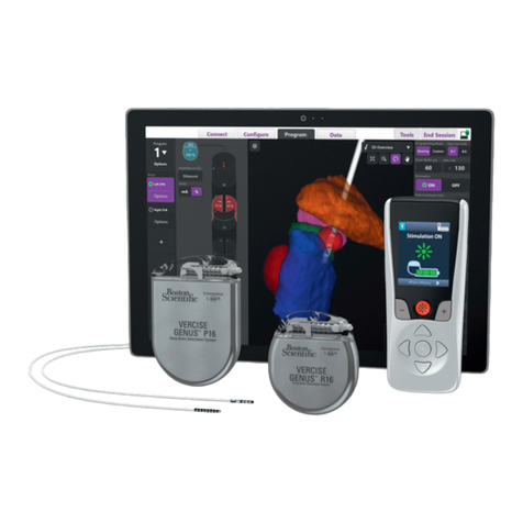
Boston Scientific Spectra WaveWriter SC-1160 Manual

CAUTION: Federal law restricts this device to sale,
distribution and use by or on the order of a physician.
Spectra WaveWriter™ SCS
System Implantable Pulse
Generator
Directions for Use
92177206-07
Content: 92265604 REV A
Directions for Use
Mode d’emploi
Gebrauchsanweisung
Gebruiksaanwijzing
en fr de nl

Implantable Pulse Generator
92177206-07 ii of iv
en
Guarantees
Boston Scientic Corporation reserves the right to modify, without prior notice, information relating to its
products in order to improve their reliability or operating capacity.
Drawings are for illustration purposes only.
Trademarks
All trademarks are the property of their respective holders.
Registration Information
In accordance with international practice and regulatory legislation in some countries, a registration form
is packed with each Boston Scientic neurostimulator. The purpose of this form is to maintain traceability
of all products and to secure warranty rights. It also allows the institution involved in the evaluation or
replacement of a specic device to gain quick access to pertinent data from the manufacturer.
Fill out the registration form included in the package contents. Return one copy to Boston Scientic, keep
one copy for patient records, provide one copy to the patient, and one copy to the physician.
Boston Scientic Neuromodulation Corporation
25155 Rye Canyon Loop
Valencia, California 91355, USA
Attention: Customer Service Department
Additional Information
For Indications and related information, see the Indications DFU. For contraindications, warnings,
precautions, adverse events summary, physician instructions, sterilization, component disposal, and
contact information for Boston Scientic, refer to the Information for Prescribers DFU for your spinal cord
stimulator system. For other device-specic instructions not included in this manual, labeling symbols, and
warranty information, refer to the appropriate DFU as listed on your Reference Guide.
Product Model Number
Model Number Description
SC-1160 Implantable Pulse Generator

Implantable Pulse Generator
92177206-07 iii of iv
en
Table of Contents
Description........................................................................................................................................................................ 1
Compatible Leads: ....................................................................................................................................................... 1
Package Contents ............................................................................................................................................................ 1
IPG Kit .......................................................................................................................................................................... 1
Max Current Amplitude per Electrode vs Impedance ................................................................................................... 2
Specications and Technical Data.................................................................................................................................. 4
Materials............................................................................................................................................................................ 4
Radiopaque Identication Tag ........................................................................................................................................ 4
Instructions for Use.......................................................................................................................................................... 5
IPG Handling and Storage ........................................................................................................................................... 5
Pre-Op Instructions ...................................................................................................................................................... 5
IPG Implantation .......................................................................................................................................................... 5
Tunneling the Lead or Lead Extension ........................................................................................................................ 6
Connecting the Lead, Extension, Splitter, or Connector to the IPG ............................................................................. 8
IPG Explant or Replacement ..................................................................................................................................... 10
Rechargeable Stimulator System ................................................................................................................................. 10
Charging Steps............................................................................................................................................................... 10
IPG Battery Status...........................................................................................................................................................11

Implantable Pulse Generator
92177206-07 iv of iv
en
This page intentionally left blank.

Description
Implantable Pulse Generator
92177206-07 1 of 53
en
Description
The Spectra WaveWriter™ Implantable Pulse Generator (IPG) system is intended to treat chronic pain
by electrically stimulating the spinal cord. The multi-channel, multi-electrode device capability provides
exibility in conjunction with ease of programming. A rechargeable battery increases IPG longevity
and output capability while reducing size and device replacement surgeries. The IPG is controlled by a
handheld Remote Control, and can be engaged by a clinician programmer using proprietary programming
software. Periodically, the IPG battery requires replenishing with an external RF charging device.
Compatible Leads:
• Innion™ 16 xx cm 16 contact lead
• Innion CX xxcm 16 Contact Lead
• Linear™ xx cm 8 Contact Leads
• Linear ST xx cm 8 Contact Leads
• Linear 3-4 xx cm 8 Contact Leads
• Linear 3-6 xx cm 8 Contact Leads
• Artisan™ 2x8 Surgical leads
• Artisan MRI xxcm 2x8 Surgical Lead
• CoverEdge™ 32 xxcm 4x8 Surgical Lead
• CoverEdge X 32 xxcm 4x8 Surgical Lead
• 8 Contact Extensions
• 2x4 Splitters
• 2x8 Splitters
Note: xx denotes length (cm).
The Spectra WaveWriter System supports any combination of 8 contact percutaneous, 16 contact
percutaneous, and 16 contact surgical Leads totaling up to 32 active contacts.
Package Contents
IPG Kit
(1) Spectra WaveWriter Implantable Pulse Generator
(1) Hex Wrench
(1) IPG Pocket Template
(4) Port Plugs
(1) Device Registration Form and Temporary Patient Identication Card

Implantable Pulse Generator
92177206-07 2 of 53
en
Max Current Amplitude per Electrode vs Impedance
For all Leads other than the 4x8 Surgical Lead
0.00
5.10
10.20
15.30
20.40
25.50
300 400 500 600 700 800 900 1000 1100 1200
Current (mA)
Impedance (Ω)
Maximum Amplitude Based on Impedance and Pulse Width
PW = 20 us
PW = 100 us
PW = 200 us
PW = 300 us
PW = 400 us
PW = 600 us
PW = 800 us
PW = 1000 us
Programmable up to 25.5 mA
Programmable up to 21.1 mA
Programmable up to 15.8 mA
Programmable up to 12.7 mA
20 µsec
100 µsec
200 µsec
300 µsec
400 µsec
600 µsec
800 µsec
1000 µsec
Pulse Width:
For the 4x8 Surgical Lead
0.00
5.10
10.20
15.30
20.40
25.50
300 400 500 600 700 800 900 1000 1100 1200
Current (mA)
Impedance (Ω)
Maximum Amplitude Based on Impedance and Pulse Width
PW = 20 us
PW = 100 us
PW = 200 us
PW = 300 us
PW = 400 us
PW = 600 us
PW = 800 us
PW = 1000 us
Programmable up to 25.5 mA
Programmable up to 17.6 mA
Programmable up to 13.2 mA
Programmable up to 10.6 mA
Pulse Width:
20 µsec
100 µsec
200 µsec
300 µsec
400 µsec
600 µsec
800 µsec
1000 µsec

Max Current Amplitude per Electrode vs Impedance
Implantable Pulse Generator
92177206-07 3 of 53
en
Max Amplitude Based on Frequency and Pulse Width
For all Leads other than the 4x8 Surgical Lead
0.00
5.10
10.20
15.30
20.40
25.50
0200 400 600 800 1000 1200
Current (mA)
Frequency (Hz)
Maximum Amplitude Based on Frequency and Pulse Width
PW = 20 us
PW = 100 us
PW = 200 us
PW = 300 us
PW = 400 us
PW = 600 us
PW = 800 us
PW = 1000 us
Pulse Width:
20 µsec
100 µsec
200 µsec
300 µsec
400 µsec
600 µsec
800 µsec
1000 µsec
For the 4x8 Surgical Lead
0.00
5.10
10.20
15.30
20.40
25.50
0200 400 600 800 1000 1200
Current (mA)
Frequency (Hz)
Maximum Amplitude Based on Frequency and Pulse Width
PW = 20 us
PW = 100 us
PW = 200 us
PW = 300 us
PW = 400 us
PW = 600 us
PW = 800 us
PW = 1000 us
Pulse Width:
20 µsec
100 µsec
200 µsec
300 µsec
400 µsec
600 µsec
800 µsec
1000 µsec

Implantable Pulse Generator
92177206-07 4 of 53
en
Specications and Technical Data
Parameter Range Default
Areas (Channels) 4 —
Amplitude 0 – 25.5 mA 0 mA
Rate 2 Hz – 1200 Hz 40 Hz
Width 20 – 1000 μsec 210 μsec
Cycle 0 sec – 90 min OFF
Ramp Up 1 – 10 secs
-or-
OFF
3 secs
Contacts 1 – 32, case: +100% to -100%, OFF 1 – 32, case: OFF
Materials
Case Titanium
Header Epoxy
Strain Relief Silicone
Size/Volume 55.0 mm x 46.0 mm x 10.8 mm / 21.2 cm3 (including header)
Radiopaque Identication Tag
The IPG contains a radiopaque identication tag “BSC IPG”. The identication tag is visible using standard
x-ray procedures.

Instructions for Use
Implantable Pulse Generator
92177206-07 5 of 53
en
Instructions for Use
IPG Handling and Storage
• Handle the IPG and all components with care.
• Keep sharp instruments away from the components.
• Do not use the IPG if it has been dropped on a hard surface.
• Do not incinerate an IPG. Improper disposal of the device could result in an explosion. Devices
should be explanted in the case of cremation, and returned to Boston Scientic Neuromodulation
Corporation. An explant kit is available.
• Store the IPG between 0 °C and 45 °C ( 32 °F and 113 °F). Devices should always be kept in
temperature regulated areas within the acceptable temperature range. IPG damage can occur at
temperatures outside of this range.
Pre-Op Instructions
1. Ensure that the IPG is fully charged prior to the permanent implant procedure. The approximate
location of the IPG is marked on the IPG kit. Turn on the Charger and place it over the IPG to begin
charging. Refer to “Charging Steps” in this manual for additional instructions.
2. Check that the sterile package is intact. (See “Sterilization” in the Information for Prescribers manual.)
3. If intra-operative stimulation testing is desired, ensure that a Trial Stimulator is available for use. Be
sure that stimulation is off (the indicator light is not blinking) before opening the Trial Stimulator’s
battery compartment. Refer to the Clinician Trial Manual for additional instructions.
IPG Implantation
1. Ensure that the area surrounding the lead entry site is incised to a dimension that will accommodate
the tunneling tool.
2. Check that the lead is securely anchored.
3. Select and mark the intended IPG site, using the IPG template, and create an incision for the IPG
pocket.
4. Create a subcutaneous pocket no larger than the IPG outline at a depth of up to 2.0 cm from the
surface. Implant charging could become ineffective at depths shallower than 0.5 cm or greater than 2.0
cm.
5. Tunnel the lead(s) to the IPG site.
Note: Using the IPG template will help guide the correct pocket sizing. It is important to keep the pocket
small to reduce the chances of patient manipulation and IPG ipping. Select an IPG site several
inches away from the previously externalized trial lead site to reduce risk of infection.
Implantable Pulse Generator
92177206-07 6 of 53
en
Tunneling the Lead or Lead Extension
Tunneling Tool Assemblies (SC-4254 and SC-4252) are sold separately. If using a 4x8 Surgical Lead or
Innion CX Lead, it is recommended to use the 35 cm Long Tunneling Tool (SC-4254).
1. If not already assembled, attach the tunneling tool handle to the shaft by turning the locking
mechanism clockwise.
Tool Handle
Locking Mechanism
Shaft
2. Mark the desired route of the tunnel.
3. Administer the appropriate local anesthetic along the tunneling path.
4. OPTIONAL. If necessary, bend the tool shaft to conform to the patient’s body.
5. Make a small incision at the desired exit site.
6. Create a subcutaneous tunnel between the lead(s) incision and the IPG pocket site until the straw is
visible and accessible at the exit point.

Instructions for Use
Implantable Pulse Generator
92177206-07 7 of 53
en
7. Unscrew and remove the tunneling tool handle.
8. Grasp the tip of the tool with one hand while holding the straw in place with the other hand. Pull the
tunneling tool shaft out through the straw.
9. Push the lead or extension through the straw, then withdraw the straw.
10. Pull the proximal end(s) out of the exit point.
11. Wipe the proximal end(s) clean.
CAUTION: Do not tunnel the splitter.
Note: If using the 2x8 Splitter and performing a permanent trial, the splitter tails may be tunneled to the
exit site.
Note: The following Codman Disposable Catheter Passers may be used in place of the Boston Scientic
tunneling tool:
REF 82-1515 (36 cm); REF 82-1516 (55 cm); REF 82-1517 (65 cm)
Note: When using a Codman Disposable Catheter Passer, tunnel from the midline incision to the IPG
pocket using the standard technique.

Implantable Pulse Generator
92177206-07 8 of 53
en
Connecting the Lead, Extension, Splitter, or Connector to the IPG
IPG ports are labeled as follows:
For convenience, connect leads or splitter tails to the IPG ports corresponding to their locations, superior
versus inferior or left versus right lead placements. For example:
• Superior leads to upper IPG ports A or B. Inferior leads to IPG ports C or D.
• For the Innion™ 16, connect the splitter tail with laser etched bands (contacts 1-8 of the Innion
16 lead) to the left ports A or C and the unmarked splitter tail (contacts 9-16 of the Innion 16 lead)
to the right ports B or D.
• For the Innion CX Lead, connect the tail with the single marker band (contacts 1-8 of the Innion
CX Lead) to the left ports A or C and the tail with two marker bands (contacts 9-16 of the Innion
CX Lead) to the right ports B or D.
• For the Artisan 2x8 surgical lead, connect the left side to the left ports A or C. Connect the right side
(the laser-etched tail), contacts 9-16, to the right ports B or D.
• For the 4x8 Surgical Lead, connect the lead tail as follows:
- Lead tail with one marker band (contacts 1-8) to port A.
- Lead tail with two marker bands (contacts 9-16) to port B.
- Lead tail with three marker bands (contacts 17-24) to port C.
- Lead tail with four marker bands (contacts 25-32) to port D.
Example: 4x8 Surgical Lead (electrodes faced down)
4
3
2
1
8
7
6
5
1Contacts 1-8 5Connects to port A
2Contacts 9-16 6Connects to port B
3 Contacts 17-24 7Connects to port C
4 Contacts 25-32 8Connects to port D

Instructions for Use
Implantable Pulse Generator
92177206-07 9 of 53
en
1. Fully insert the lead(s), extension(s), splitter(s), and/or connector(s) into the IPG port(s), being careful
not to stress or bend the proximal end of the lead. When the lead is properly inserted, the lead will stop
and the retention ring will be located under the set screw.
2. Fully insert a port plug into unused IPG ports.
Note: If you experience difculty when inserting the lead, lead extension, splitter, connector, or port plug,
use the hex wrench to loosen (counterclockwise) the set screw and/or gently rotate the lead to help
advance the proximal end.
Note: To conrm good connections, check impedances before tightening the set screw. The IPG must be
in contact with the subcutaneous pocket in order to receive accurate impedance measurements.
3. Pass the hex wrench through the hole in the septum located on the front or back of the IPG header
and tighten each set screw until the hex wrench “clicks,” indicating lock.
CAUTION: Ensure that the lead is fully inserted before tightening the set screw to prevent lead
damage
Note: If a port plug is used, it is still necessary to tighten the set screw on the port plug as described
above.
Note: The hex wrench is torque-limited and cannot be over-tightened.
4. Place the IPG in the subcutaneous pocket with logo marking facing up towards the skin.
5. Coil excess lead, extension, splitter, or connector under the IPG.
6. If desired, secure the IPG in the pocket by suturing through the holes in the IPG header.
CAUTION: Do not suture through the leads or splitter.
7. Close and dress the wound(s).

Implantable Pulse Generator
92177206-07 10 of 53
en
IPG Explant or Replacement
1. Turn off the IPG.
2. Surgically open the IPG pocket and withdraw the device. Please try to preserve the integrity of all
components so that complete device assessment can be performed.
3. Loosen the connector set screws to release and remove the leads, extensions, or splitters.
4. For replacement, connect the new IPG following the instructions for “Connecting the Lead, Extension,
Splitter, or Connector to the IPG” on page 8. Or, to terminate therapy, surgically remove the
implanted lead system.
5. Notify Boston Scientic to document the reason for explant or replacement and to arrange for return of
IPG and components.
Rechargeable Stimulator System
The Spectra WaveWriter Stimulator is rechargeable. Boston Scientic recommends any recharge routine
that ts the patient’s schedule and lifestyle while maintaining sufcient charge to maintain stimulation.
Developing a patient’s recharge routine involves nding the right balance among the following:
• How much power is required for the patient to experience effective therapy.
• How often the patient wants to recharge.
• How long the patient wants to recharge.
• How the patient would like to manage their personal schedule.
The Clinician Programmer will estimate charging time based on 24 hours per day of stimulation at the
programmed settings. To charge fully, wait until the Charger emits an end of charge beep signal or the
Remote Control display indicates that the battery is charged. Refer to the Patient Charger Handbook
and the Clinician Remote Control Directions for Use for additional information. The recharging process is
simple, but important.
Charging Steps
WARNINGS:
• Patient should not charge while sleeping. This may result in a burn.
• While charging, the Charger may become warm. It should be handled with care.
• Failure to use the Charger with either the Charger Belt or an adhesive patch, as shown, may result
in a burn. If pain or discomfort is felt, cease charging and contact Boston Scientic.
The Charger Base Station should be plugged in and the Charger placed in the Base Station when not
in use. When the indicator light is green, the Charger is fully charged. When the indicator is amber, the
Charger is partially charged, but is still able to deliver a charge to the Stimulator.
1. When the indicator light is green, remove the Charger from the Base Station. The indicator light will
then turn off.
2. Press the power button. The indicator light will come on again, and the Charger will begin beeping as it
searches for the Stimulator.
3. Place the Charger over the Stimulator. When the Charger is aligned with the Stimulator, the beeping
will stop.
• Centering the Charger over the Stimulator will ensure the shortest charging time.
• Many patients are able to feel the implanted Stimulator and can place the Charger directly on
top of it.

IPG Battery Status
Implantable Pulse Generator
92177206-07 11 of 53
en
• Alternatively, centering the Charger within the alignment area (i.e., the area where the Charger
does not beep) will also ensure that the Charger is aligned.
4. Secure the Charger over the Stimulator by using either an adhesive patch or the Charger Belt.
• Adhesive Patch: Remove the clear liner from the patch. Apply the white side with the blue
stripe to the back of the Charger. Then remove the beige liner from the patch. Secure the
Charger over the Stimulator by pressing the adhesive to the skin over the Stimulator.
• Charger Belt: Place the Charger into the pocket on the Charger Belt so that the Power button
is visible through the mesh fabric. Secure the Charger over the Stimulator by adjusting the
Charger Belt.
Note: If you accidentally locate the patch in the wrong place, or if the Charger Belt moves out of
alignment, the Charger will start beeping again. Use a new adhesive patch or readjust the belt to
place the Charger back into position.
5. When the Charger emits a series of double beeps, the Stimulator is fully charged. Turn off the Charger,
remove the Charger Belt or adhesive patch, and return the Charger to the Base Station. Do not
confuse the end of charge signal (a series of double beeps) with the continuous beeps that indicate
that the Charger is searching for the Stimulator.
Note: • The end of a charge signal is a distinct double beep, and the alignment indicator is a steady
continuous signal.
• The Remote Control will not be able to communicate with the IPG when charging.
Refer to “IPG Battery Life” in your Information for Prescribers manual for information on Stimulator battery
life.
IPG Battery Status
The patient Remote Control displays the Stimulator battery status when communicating with the
Stimulator. Refer to the Clinician Remote Control Directions for Use for additional information. When the
Remote Control indicates a low battery the Stimulator should be recharged as soon as possible.
Failure to recharge may lead to loss of stimulation in less than 24 hours. After stimulation stops,
communication with the Stimulator will also cease. Until a sufcient level of charge has been attained, the
Stimulator may not communicate with the Remote Control.

Générateur d’impulsions implantable
92177206-07 12 sur 53
fr
Garanties
Boston Scientic Corporation se réserve le droit de modier, sans préavis, les informations relatives à ses
produits dans le but d'améliorer leur abilité ou leur capacité de fonctionnement.
Les dessins et schémas sont présentés à des ns d'illustration uniquement.
Marques commerciales
Toutes les marques commerciales appartiennent à leurs propriétaires respectifs.
Informations relatives à l’enregistrement
Conformément aux pratiques internationales et à la législation de certains pays, un formulaire
d′enregistrement est fourni avec chaque neurostimulateur Boston Scientic. Ce formulaire a pour objectif
de garantir la traçabilité de tous les produits et de protéger les droits de garantie. Il permet également à
l′organisme impliqué dans l′évaluation ou le remplacement d′un dispositif spécique d′accéder rapidement
aux données importantes du fabricant.
Remplissez le formulaire d′enregistrement fourni dans l′emballage. Renvoyez un exemplaire à Boston
Scientic, conservez-en un pour le dossier du patient et remettez-en un au patient et un au médecin.
Boston Scientic Neuromodulation Corporation
25155 Rye Canyon Loop
Valencia, California 91355, États-Unis
Attention : Customer Service Department
Informations complémentaires
Pour connaître les indications et les informations connexes, consultez les Indications d’utilisation. Pour
les contre-indications, avertissements, précautions, le résumé des effets indésirables, les instructions
destinées aux médecins, les règles de stérilisation et de mise au rebut des composants et les
coordonnées de Boston Scientic, veuillez consulter le manuel d’information destiné aux prescripteurs
de votre système de stimulation médullaire. Pour toute autre instruction spécique à l’appareil non
présente dans ce manuel, les symboles qui apparaissent sur les étiquettes et les informations de garantie,
consultez le manuel approprié, comme indiqué dans votre Guide de référence.
Numéro de modèle du produit
Numéro de modèle Descr iption
SC-1160 Générateur d'impulsions implantable

Générateur d’impulsions implantable
92177206-07 13 sur 53
fr
Table des matières
Description...................................................................................................................................................................... 15
Sondes compatibles : ................................................................................................................................................. 15
Contenu de l'emballage ................................................................................................................................................. 15
Kit du GII .................................................................................................................................................................... 15
Amplitude maximale du courant par électrode par rapport à l’impédance .............................................................. 16
Spécications et données techniques ......................................................................................................................... 18
Matériaux......................................................................................................................................................................... 18
Étiquette d'identication radio-opaque........................................................................................................................ 18
Mode d′emploi................................................................................................................................................................. 18
Manipulation et stockage du GII ................................................................................................................................ 18
Instructions pré-opératoires ....................................................................................................................................... 19
Implantation du GII ..................................................................................................................................................... 19
Tunnellisation de la sonde ou de la prolongation ....................................................................................................... 20
Connexion de la sonde, de la prolongation, du répartiteur ou du connecteur au GII ................................................. 22
Explantation ou remplacement du GII ........................................................................................................................ 24
Système de stimulation rechargeable.......................................................................................................................... 24
Étapes de chargement ................................................................................................................................................... 24
Niveau de charge de la batterie du GII ......................................................................................................................... 25

Générateur d’impulsions implantable
92177206-07 14 sur 53
fr
Page volontairement laissée blanche.

Description
Générateur d’impulsions implantable
92177206-07 15 sur 53
fr
Description
Le générateur d’impulsions implantable (GII) Spectra WaveWriter™ est conçu pour traiter la douleur chronique
par stimulation électrique de la moelle épinière. Avec ses options à canaux et à électrodes multiples, le système
offre une grande exibilité et permet une programmation aisée. La batterie rechargeable permet d′accroître la
longévité et la capacité du GII et de réduire l′ampleur et le nombre d′opérations chirurgicales nécessaires au
remplacement du dispositif. Le GII est contrôlé par une télécommande de poche et peut être activé par un
programmateur clinicien au moyen du logiciel de programmation exclusif. La batterie du GII doit être rechargée
régulièrement à l'aide du chargeur RF externe.
Sondes compatibles :
• Sonde Innion™ 16 xx cm 16 contacts
• Kit de sonde Innion CX à 16 contacts xx cm
• Sondes Linear™ xx cm 8 contacts
• Sondes Linear ST xx cm 8 contacts
• Sondes Linear 3-4 xx cm 8 contacts
• Sondes Linear 3-6 xx cm 8 contacts
• Sondes chirurgicales Artisan™ 2x8
• Sonde chirurgicale Artisan xx cm 2x8 compatible IRM
• Sonde chirurgicale CoverEdge™ 32 xx cm 4x8
• Sonde chirurgicale CoverEdge X 32 xx cm 4x8
• Extensions 8 contacts
• Répartiteurs 2x4
• Répartiteurs 2x8
Remarque : xx indique la longueur (cm)
Le système Spectra WaveWriter prend en charge toutes les associations de sondes percutanées à 8 contacts,
de sondes percutanées à 16 contacts et de sondes chirurgicales à 16 contacts, pouvant totaliser jusqu’à
32 contacts actifs.
Contenu de l'emballage
Kit du GII
(1) Générateur d’impulsions implantable Spectra WaveWriter
(1) Clé hexagonale
(1) Gabarit de poche du GII
(4) Bouchons de port
(1) Formulaire d'enregistrement du dispositif et carte d'identication temporaire du patient

Générateur d’impulsions implantable
92177206-07 16 sur 53
fr
Amplitude maximale du courant par électrode par rapport à l’impédance
Pour toutes les sondes autres que la sonde chirurgicale 4x8
0.00
5.10
10.20
15.30
20.40
25.50
300 400 500 600 700 800 900 1000 1100 1200
Current (mA)
Impedance (Ω)
Maximum Amplitude Based on Impedance and Pulse Width
PW = 20 us
PW = 100 us
PW = 200 us
PW = 300 us
PW = 400 us
PW = 600 us
PW = 800 us
PW = 1000 us
Programmable jusqu'à 25,5 mA
Programmable jusqu'à 21,1 mA
Programmable jusqu'à 15,8 mA
Programmable jusqu'à 12,7 mA
20 µs
100 µs
200 µs
300 µs
400 µs
600 µs
800 µs
1000 µs
Largeur d’impulsion :
Pour la sonde chirurgicale 4x8
0.00
5.10
10.20
15.30
20.40
25.50
300 400 500 600 700 800 900 1000 1100 1200
Current (mA)
Impedance (Ω)
Maximum Amplitude Based on Impedance and Pulse Width
PW = 20 us
PW = 100 us
PW = 200 us
PW = 300 us
PW = 400 us
PW = 600 us
PW = 800 us
PW = 1000 us
Programmable jusqu'à 25,5 mA
Programmable jusqu'à 17,6 mA
Programmable jusqu'à 13,2 mA
Programmable jusqu'à 10,6 mA
Largeur d’impulsion :
20 µs
100 µs
200 µs
300 µs
400 µs
600 µs
800 µs
1000 µs
Impédance (Ω)
Impédance (Ω)
Intensité (mA) Intensité (mA)
Table of contents
Languages:
Other Boston Scientific Pulse Generator manuals