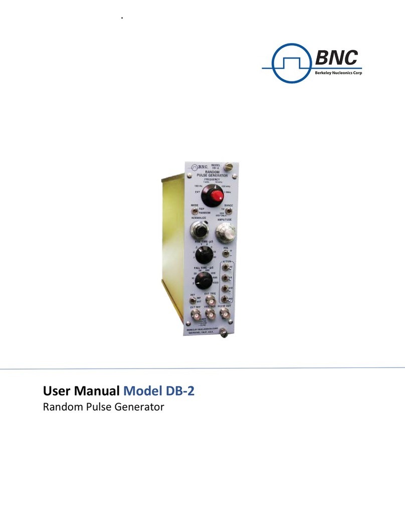
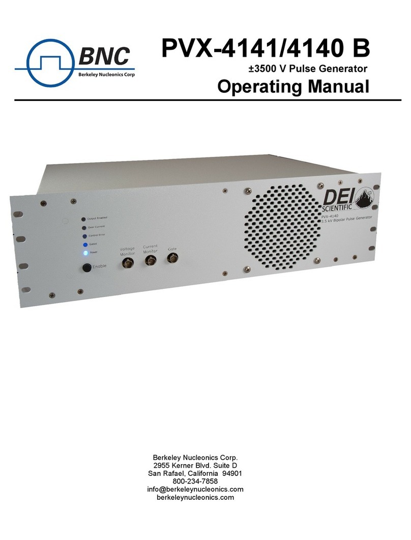
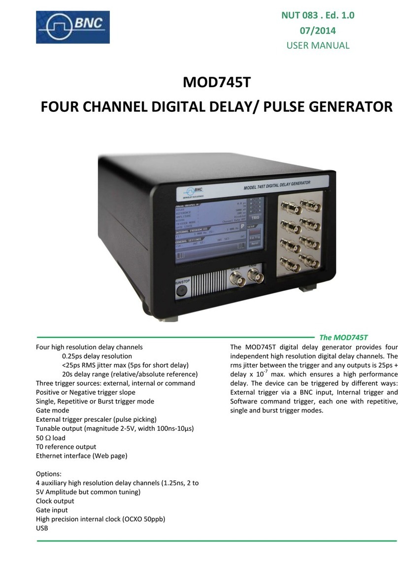
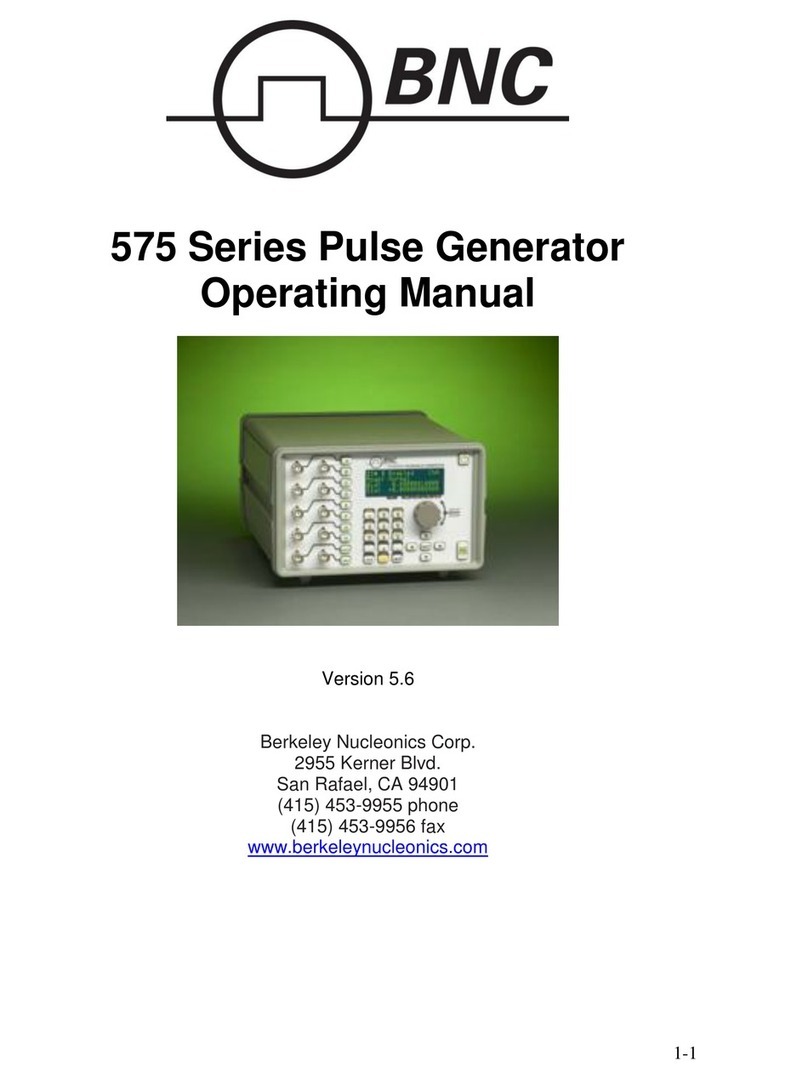
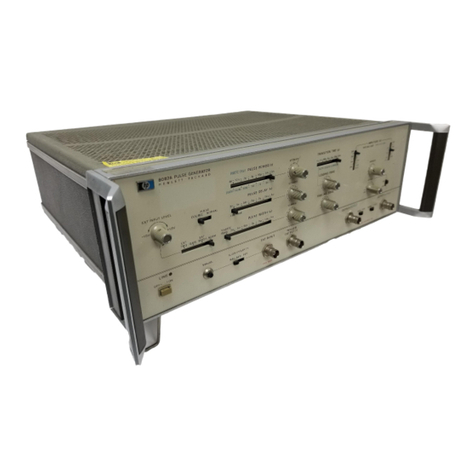
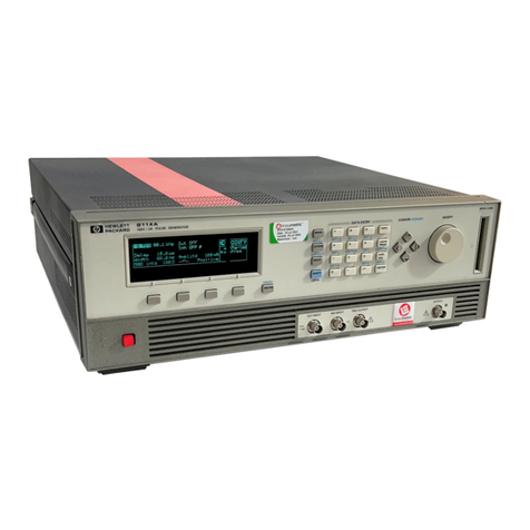
BNC 507 Series User manual

507 Series
Pulse Generator
User's Manual
BNC

10Main Menu ................................ ..................... 10Item Edit Mode ......................... ..................... 10Numeric Input Mode .................... ..................... 10Selecting Menu Items .................... ..................... 9Overview .................................. ...................... 93 Operating Instructions ...................... ...................... 8ACInput ............................. ...................... 8GPIB Port (optional) .................. ...................... 7Serial Port .......................... ...................... 7Interlock ............................ ...................... 7Rear Panel ................................ ...................... 7Interlock (Toggle Switch) .............. ...................... 7Sync Out ............................ ...................... 7
External Trigger ...................... ...................... 6
Output Sections ...................... ...................... 6Run Button .......................... ...................... 6Stop Button ......................... ...................... 6Right Button ......................... ...................... 6Left Button .......................... ...................... 5Down Button ........................ ...................... 5Up Button ........................... ...................... 5Menu Button ......................... ...................... 5Enter Button ......................... ...................... 5Control Buttons ......................... ...................... 5Display ................................ ...................... 5Front Panel ................................ ...................... 52 Controls and Connectors ................... ...................... 2Safety Issues .............................. ...................... 2Custom Modifications ....................... ...................... 1Warranty .................................. ...................... 1Parts List .................................. ...................... 1Technical Support .......................... ...................... 11 Introduction ................................ ......................
Table of Contents
i

23Long Pulse Option Specifications ............ ..................... 237 Custom Features ........................... ..................... 21Replacing the Fuse ......................... ..................... 216 Maintenance ............................... ..................... 20General ................................... ..................... 20Computer Interface ......................... ..................... 20Outputs ................................... ..................... 19Internal Rate Generator ..................... ..................... 19External Trig/Gate .......................... ..................... 19Delays .................................... ..................... 195 Specifications .............................. ..................... 18Command Listing .......................... ..................... 17Communication Protocol ................. ..................... 16Command Protocol ...................... ..................... 16Command Language ....................... ..................... 15
GPIB ..................................... ..................... 15Serial (RS232) Pinout ....................... ..................... 154 Computer Interface ......................... ..................... 13
GPIB:Addr (optional) .................... ..................... 13Volume ................................ .................... 13Fmark ................................. ..................... 13Shot Counter ........................... ..................... 12RECALL Configuration ................... ..................... 12STORE Configuration .................... ..................... 12Store/Recall Menus ........................ ..................... 12n:Wid - Tn:Pulse Width .................. ..................... 11n:Dly - Tn:Delay ........................ ..................... 11n:lamps - Tn:lamps ..................... ..................... 11n:Enable - Tn:Enable .................... ..................... 11Channel Menus ........................... ..................... 11Single Shot Mode .................... ..................... 10External Trigger Mode ................ ..................... 10MODE - Pulse Modes .................. .....................
Table of Contents
ii

Table of Contents
iii

1INTRODUCTION
This manual is designed to help you quickly and easily learn to use your Berkeley
Nucleonics Model 507 current pulse generator. The 507 provides digitally controlled
current pulses with currents from 0 - 25 Amps and pulsewidths from 100μs to 100ms.
We also offer a long pulse version which holds up to 10A for 10μs - 500ms. Rather
than the usual array of knobs and switches, the 507 uses a menu-driven user interface
with "on-line" help -- once you learn the basics of operating your 507, you may never
need to refer to this manual again.
Since the Model 507 employs a flexible microprocessor-controlled architecture, the
507 can be customized to fit your exact requirements -- contact Berkeley Nucleonics
for details.
Technical Support
For questions or comments about operating the 507, contact Berkeley Nucleonics via
one of the following methods:
PPhone - (415) 453-9955
PFax - (415) 453-9956
PInternet - www.berkeleynucleonics.com
Parts List
The following parts are included with the 507 -- contact Berkeley Nucleonics if any
parts are missing:
P507 Pulse Generator
PAC Power Cord
PUser's Manual
Warranty
In addition to a 30-day money back guarantee, the Model 507 has a one-year limited
warranty from the date of delivery. This warranty covers defects in materials and
workmanship. Berkeley Nucleonics will repair or replace any defective unit.
1

Custom Modifications
The 507 is microprocessor-controlled and employs a flexible and expandable
user-interface. New features and operating modes often can be added without
hardware modifications by merely modifying the software contained inside the 507 -
contact Berkeley Nucleonics for details.
Safety Issues
Normal use of test equipment exposes users to a certain amount of danger from
electrical shock because testing must be performed where exposed voltage is present.
An electrical shock causing 10 milliamps of current to pass through the heart will
stop most human heartbeats. Voltage as low as 35 VDC or RMS AC should be
considered dangerous and hazardous since it can produce a lethal current under
certain conditions. Higher voltages pose an even greater threat because such voltage
can more easily produce a lethal current. Your normal work habits should include all
accepted practices that will prevent contact with exposed high voltage, and those that
will steer current away from your heart in case of accidental contact with a high
voltage. You will significantly reduce the risk factor if you know and observe the
following safety precautions:
1. Do not expose high voltage components needlessly. Remove
housings and covers only when necessary. Turn off
equipment while making test connections in high-voltage
circuits. Discharge high-voltage capacitors after removing
power.
2. If possible, familiarize yourself with the equipment being
tested and the location of high voltage points. However,
remember that high voltage may appear at unexpected points
in defective equipment.
3. Use an insulated floor material or a large, insulated floor mat
to stand on, and an insulated work surface on which to place
equipment. Make certain such surfaces are not damp or wet.
4. Use the time-proven "one hand in the pocket" technique
while handling an instrument probe. Be particularly careful
to avoid contacting a nearby metal object that could provide a
good ground return path.
5. When testing AC powered equipment, remember that AC line
voltage is usually present on some power input circuits, such
2
as the on-off switch, fuses, power transformer etc., any time
the equipment is connected to an AC outlet, even if the
equipment is turned off.
6. Never work alone. Someone should always be nearby to
render aid if necessary. Training in CPR first aid is highly
recommended.
3

4

2CONTROLS AND CONNECTORS
This chapter explains the function of each control and connector on the 507.
Front Panel
The front panel contains the most frequently used controls and connectors.
Display
The 507 features a backlit liquid crystal display, which displays menu selections and
settings. The left half of the display shows the current menu selection, while the right
half shows the current setting of the item associated with that menu.
Control Buttons
Item Button
Toggles between the various items in a menu.
Menu Button
Toggles between the various sets of menus.
Up Button
Increments a number or increments the selection for the current item.
Down Button
Decrements a number or increments the selection for the current item.
5

Left Button
For numeric items, this button is used to select which digit in a numeric entry is
selected for editing. For other items, or when the left most digit is already selected
for numeric items, pressing and holding this button down displays a brief description
of the current item.
Right Button
For numeric items, this button is used to select which digit in a numeric entry is
selected for editing. For other items, or when the right most digit is already selected
for numeric items, press and hold this button down to display the range and units for
the current item.
Stop Button
Disables output of pulses on all channels.
Run Button
Enables output of pulses.
Output Sections
There are two (2) output sections on the front of the 507; each consists of a pair of
banana plugs, a BNC current monitor, a toggle switch, and a charge level indicator.
Each output section is independently controlled and isolated from each other. Loads
are connected to the banana plugs. The toggle switch allows the user to physically
disconnect the output (off position). Disconnecting the outputs is recommended
while connecting loads.
Warning: The charge bank voltage is present on the positive (red) output jack;
before connecting loads, disconnect bank voltage by placing toggle switch in off
position.
6
Table of contents
Other BNC Pulse Generator manuals
Popular Pulse Generator manuals by other brands

Agilent Technologies
Agilent Technologies 81150A Getting started guide

Abbott
Abbott Eterna 32400 Clinician manual

DEI
DEI PCX-7500 Operation manual

Quantum Composers
Quantum Composers 9510+ Series datasheet

DORIC
DORIC Optogenetics TTL user manual

AVTECH ELECTROSYSTEMS LTD.
AVTECH ELECTROSYSTEMS LTD. AVG-4A-B instructions